- You are here:
-
Home

-
Contents
-
Part XIII. Manufacturing Industries
- Electrical Appliances and Equipment

81. Electrical Appliances and Equipment
Chapter Editor: N. A. Smith
Table of Contents
Tables and Figures
General Profile
N. A. Smith
Lead-Acid Battery Manufacture
Barry P. Kelley
Batteries
N. A. Smith
Electric Cable Manufacture
David A. O’Malley
Electric Lamp and Tube Manufacture
Albert M. Zielinski
Domestic Electrical Appliance Manufacture
N. A. Smith and W. Klost
Environmental and Public Health Issues
Pittman, Alexander
Tables
Click a link below to view table in article context.
1. Composition of common batteries
2. Manufacture: domestic electrical appliances
Figures
Point to a thumbnail to see figure caption, click to see figure in article context.


General Profile
Overview of the Sector
Electrical equipment includes a wide-ranging field of devices. It would be impossible to include information on all items of equipment, and this chapter will therefore be limited to coverage of products of some of the major industries. Numerous processes are involved in the manufacture of such equipment. This chapter discusses the hazards likely to be encountered by persons working in the manufacture of batteries, electric cables, electric lamps and general domestic electrical equipment. It concentrates upon electrical equipment; electronic equipment is discussed in detail in the chapter Microelectronics and semiconductors.
Evolution of the Industry
The pioneering discovery of electromagnetic induction was instrumental in the development of today’s vast electrical industry. The discovery of the electrochemical effect led to the development of batteries as a means of supplying electrical equipment from portable power sources using direct current systems. As devices which relied upon power from mains were invented, a system of transmission and distribution of electricity was required, which led to the introduction of flexible electrical conductors (cables).
The early forms of artificial lighting (i.e., carbon arc and gas lighting) were superseded by the filament lamp (originally with a carbon filament, exhibited by Joseph Swan in England in January 1879). The filament lamp was to enjoy an unprecedented monopoly in domestic, commercial and industrial applications prior to the outbreak of the Second World War, at which stage the fluorescent lamp was introduced. Other forms of discharge lighting, all of which depend upon the passage of an electric current through a gas or vapour, have subsequently been developed and have a variety of applications in commerce and industry.
Other electrical appliances in many fields (e.g., audio-visual, heating, cooking and refrigeration) are constantly being developed, and the range of such devices is increasing. This is typified by the introduction of satellite television and the microwave cooker.
While the availability and accessibility of raw materials had a significant effect upon the development of the industries, the locations of the industries were not necessarily determined by the locations of the raw material sources. The raw materials are often processed by a third party before being used in the assembly of electrical appliances and equipment.
Characteristics of the Workforce
The skills and expertise possessed by those who work in the industry now are different from those possessed by the workforce in earlier years. Equipment used in the production and manufacture of batteries, cables, lamps and domestic electrical appliances is highly automated.
In many instances those who are currently involved in the industry require specialized training in order to carry out their work. Teamwork is a significant factor in the industry, since many processes involve production line systems, where the work of individuals depends upon the work of others.
An ever-increasing number of manufacturing processes involved in the production of electrical appliances rely on some form of computerization. It is necessary, therefore, for the workforce to be familiar with computer techniques. This may not present any problems to the younger workforce, but older workers may not have had any previous computer experience, and it is likely that they will need to be re-trained.
Economic Importance of the Industry
Some countries benefit more than others from the electrical appliances and equipment industry. The industry has economic importance for those countries from which raw materials are obtained and those in which the end products are assembled and/or constructed. Assembly and construction take place in many different countries.
Raw materials do not have infinite availability. Discarded equipment should be re-used wherever possible. However, the costs involved in recovering those parts of discarded equipment which may be re-used may ultimately be prohibitive.
Lead-Acid Battery Manufacture
The first practical design of a lead-acid battery was developed by Gaston Planté in 1860, and production has continued to grow steadily since. Automotive batteries represent the major use of lead-acid technology, followed by industrial batteries (stand-by power and traction). More than half the worldwide production of lead goes into batteries.
The low cost and ease of manufacture of lead-acid batteries in relation to other electrochemical couples should ensure a continuing demand for this system in the future.
The lead-acid battery has a positive electrode of lead peroxide (PbO2) and a negative electrode of high surface area spongy lead (Pb). The electrolyte is a sulphuric acid solution with specific gravity in the range 1.21 to 1.30 (28 to 39% by weight). On discharge, both electrodes convert to lead sulphate, as shown below:
![]()
Manufacturing Process
The manufacturing process, which is shown in the process flow chart (figure 1), is described below:
Figure 1. Lead-acid battery manufacturing process
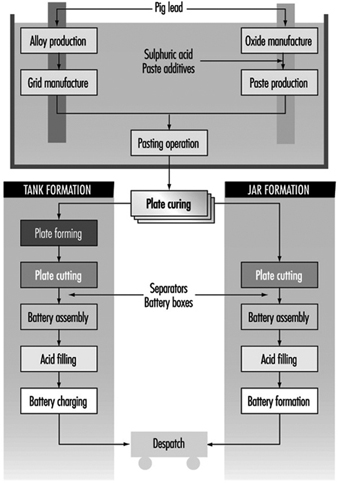
Oxide manufacture: Lead oxide is manufactured from pigs of lead (masses of lead from smelting furnaces) by one of two methods—a Barton Pot or a milling process. In the Barton Pot process, air is blown over molten lead to produce a fine stream of lead droplets. The droplets react with oxygen in the air to form the oxide, which consists of a core of lead with a lead oxide (PbO) coating.
In the milling process, solid lead (which may range in size from small balls to complete pigs) is fed into a rotating mill. The tumbling action of the lead generates heat and the surface of the lead oxidizes. As the particles roll around in the drum, the surface layers of oxide are removed to expose more clean lead for oxidation. The airstream carries the powder to a bag filter, where it is collected.
Grid production: Grids are produced mainly by casting (both automatic and manual) or, particularly for automotive batteries, expansion from wrought or cast lead alloy.
Pasting: Battery paste is made by mixing the oxide with water, sulphuric acid and a range of proprietary additives. The paste is pressed by machine or hand into the grid lattice, and the plates are usually flash-dried in a high-temperature oven.
Pasted plates are cured by storing them in ovens under carefully controlled conditions of temperature, humidity and time. Free lead in the paste converts to lead oxide.
Formation, plate cutting and assembly: Battery plates undergo an electrical formation process in one of two ways. In tank formation, plates are loaded into large baths of dilute sulphuric acid and a direct current is passed to form the positive and negative plates. After drying, the plates are cut and assembled, with separators between them, into battery boxes. Plates of like polarity are connected by welding together the plate lugs.
In jar formation, the plates are electrically formed after being assembled into battery boxes.
Occupational Health Hazards and Controls
Lead
Lead is the major health hazard associated with battery manufacture. The principal exposure route is through inhalation, but ingestion can also pose a problem if insufficient attention is paid to personal hygiene. Exposure can occur at all stages of production.
Lead oxide manufacture is potentially very hazardous. Exposures are controlled by automating the process, thus removing the workers from the hazard. In many factories the process is operated by one person.
In grid casting, exposures to lead fumes are minimized by the use of local exhaust ventilation (LEV) together with thermostatic control of lead pots (lead fume emissions increase markedly above 500 C). Lead-bearing dross, which forms on top of the molten lead, can also cause problems. The dross contains a large amount of very fine dust, and great care has to be exercised when disposing of it.
Pasting areas have traditionally resulted in high lead exposures. The manufacturing method often results in splashes of lead slurry getting onto machinery, the floor, aprons and boots. These splashes dry out and produce airborne lead dust. Control is achieved by keeping the floor permanently wetted and frequently sponging down aprons.
Lead exposures in other departments (forming, plate cutting and assembly) occur through handling dry, dusty plates. Exposures are minimized by LEV together with appropriate use of personal protective equipment.
Many countries have legislation in place to limit the degree of occupational exposure, and numerical standards exist for lead-in-air and blood lead levels.
An occupational health professional is normally employed to take blood samples from exposed workers. The frequency of blood testing can range from annual for low-risk workers to quarterly for those in high-risk departments (e.g., pasting). If a worker’s blood lead level exceeds the statutory limit, then the worker should be removed from any work exposure to lead until the blood lead falls to a level deemed acceptable by the medical adviser.
Air sampling for lead is complementary to blood lead testing. Personal, rather than static, sampling is the preferred method. A large number of lead-in-air samples is usually required because of the inherent variability in results. Use of the correct statistical procedures in analysing the data can give information on sources of lead and can provide a basis for making improvements to engineering design. Regular air sampling can be used to assess the continuing effectiveness of control systems.
The allowable lead-in-air concentrations and blood lead concentrations vary from country to country, and presently range from 0.05 to 0.20 mg/m3 and 50 to 80 mg/dl respectively. There is a continuing downward trend in these limits.
In addition to the normal engineering controls, other measures are necessary to minimize lead exposures. There should be no eating, smoking, drinking or gum chewing in any production area.
Suitable washing and changing facilities should be provided to enable work clothing to be kept in a separate area from personal clothing and footwear. Washing/shower facilities should be located between the clean and dirty areas.
Sulphuric acid
During the formation process the active material on the plates is converted to PbO2 at the positive and Pb at the negative electrode. As the plates become fully charged, the formation current begins to dissociate the water in the electrolyte into hydrogen and oxygen:
Positive: ![]()
Negative: ![]()
Gassing generates sulphuric acid mist. Tooth erosion was, at one time, a common feature among workers in formation areas. Battery companies have traditionally employed the services of a dentist, and many continue to do so.
Recent studies (IARC 1992) have suggested a possible link between exposures to inorganic acid mists (including sulphuric acid) and cancer of the larynx. Research continues in this area.
The occupational exposure standard in the UK for sulphuric acid mist is 1 mg/m3. Exposures can be kept below this level with LEV in place over the formation circuits.
Skin exposure to the corrosive sulphuric acid liquid is also of concern. Precautions include personal protection equipment, eyewash fountains and emergency showers.
Talc
Talc is used in certain hand-casting operations as a mould release agent. Long-term exposure to talc dust can cause pneumoconiosis, and it is important that the dust be controlled by suitable ventilation and process control measures.
Man-made mineral fibres (MMFs)
Separators are used in lead-acid batteries to electrically insulate the positive from the negative plates. Various types of material have been used over the years (e.g., rubber, cellulose, polyvinyl chloride (PVC), polyethylene), but, increasingly, glass fibre separators are being used. These separators are manufactured from MMFs.
An increased risk of lung cancer amongst workers was demonstrated in the early days of the mineral wool industry (HSE 1990). However, this may have been caused by other carcinogenic materials in use at the time. It is prudent nevertheless to ensure that any exposure to MMFs is kept to a minimum by either total enclosure or LEV.
Stibine and arsine
Antimony and arsenic are commonly used in lead alloys, and stibine (SbH3) or arsine (AsH3) can be produced under certain circumstances:
- when a cell is given excessive overcharge
- when dross from a lead calcium alloy is mixed with dross from a lead antimony or lead arsenic alloy. The two drosses can react chemically to form calcium stibide or calcium arsenide which, on subsequent wetting, can generate SbH3 or AsH3.
Stibine and arsine are both highly toxic gases which act by destroying red blood cells. Strict process controls during battery manufacture should prevent any risk of exposure to these gases.
Physical hazards
A variety of physical hazards also exists in battery manufacturing (e.g., noise, molten metal and acid splashes, electrical hazards and manual handling), but the risks from these can be reduced by appropriate engineering and process controls.
Environmental Issues
The effect of lead on the health of children has been extensively studied. It is therefore very important that environmental releases of lead be kept to a minimum. For battery factories, the most polluting air emissions should be filtered. All process waste (usually an acidic lead-bearing slurry) should be processed at an effluent treatment plant to neutralize the acid and settle out the lead from the suspension.
Future Developments
It is likely that there will be increasing restrictions on the use of lead in the future. In an occupational sense this will result in increasing automation of processes so that the worker is removed from the hazard.
Batteries
The term battery refers to a collection of individual cells, which can generate electricity though chemical reactions. Cells are categorized as either primary or secondary. In primary cells, the chemical reactions that produce the electron flow are not reversible, and therefore the cells are not easily recharged. Conversely, secondary cells must be charged prior to their use, which is achieved by passing an electrical current through the cell. Secondary cells have the advantage that they can often be repeatedly recharged and discharged through use.
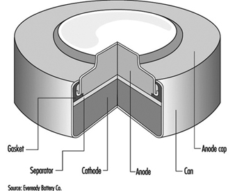
The classic primary battery in everyday use is the Leclanché dry cell, so called because the electrolyte is a paste, not a liquid. The Leclanché cell is typified by the cylindrical batteries used in flashlights, portable radios, calculators, electric toys and the like. In recent years, alkaline batteries, such as the zinc-manganese dioxide cell, have become more prevalent for this type of use. Miniature or “button” batteries have found use in hearing aids, computers, watches, cameras and other electronic equipment. The silver oxide-zinc cell, mercury cell, the zinc-air cell, and the lithium-manganese dioxide cell are some examples. See figure 1 for a cutaway view of a typical alkaline miniature battery.
Figure 1. Cutaway view of alkaline miniature battery
The classic secondary or storage battery is the lead-acid battery, widely used in the transportation industry. Secondary batteries are also used in power plants and industry. Rechargeable, battery-operated tools, toothbrushes, flashlights and the like are a new market for secondary cells. Nickel-cadmium secondary cells are becoming more popular, especially in pocket cells for emergency lighting, diesel starting and stationary and traction applications, where the reliability, long life, frequent rechargeability and low-temperature performance outweigh their extra cost.
Rechargeable batteries under development for use in electric vehicles utilize lithium-ferrous sulphide, zinc-chlorine and sodium-sulphur.
Table 1 gives the composition of some common batteries.
Table 1. Composition of common batteries
|
Type of battery |
Negative electrode |
Positive electrode |
Electrolyte |
|
Primary cells |
|||
|
Leclanché dry cell |
Zinc |
Manganese dioxide |
Water, zinc chloride, ammonium chloride |
|
Alkaline |
Zinc |
Manganese dioxide |
Potassium hydroxide |
|
Mercury (Ruben’s cell) |
Zinc |
Mercuric oxide |
Potassium hydroxide, zinc oxide, water |
|
Silver |
Zinc |
Silver oxide |
Potassium hydroxide, zinc oxide, water |
|
Lithium |
Lithium |
Manganese dioxide |
Lithium chlorate, LiCF3SO3 |
|
Lithium |
Lithium |
Sulphur dioxide |
Sulphur dioxide, acetonitrile, lithium bromide |
|
Thionyl chloride |
Lithium aluminium chloride |
||
|
Zinc in air |
Zinc |
Oxygen |
Zinc oxide, potassium hydroxide |
|
Secondary cells |
|||
|
Lead-acid |
Lead |
Lead dioxide |
Dilute sulphuric acid |
|
Nickel-iron (Edison battery) |
Iron |
Nickel oxide |
Potassium hydroxide |
|
Nickel-cadmium |
Cadmium hydroxide |
Nickel hydroxide |
Potassium hydroxide, possibly lithium hydroxide |
|
Silver-zinc |
Zinc powder |
Silver oxide |
Potassium hydroxide |
Manufacturing Processes
While there are clear differences in the manufacture of the different types of batteries, there are several processes which are common: weighing, grinding, mixing, compressing and drying of constituent ingredients. In modern battery plants many of these processes are enclosed and highly automated, using sealed equipment. Therefore, exposure to the various ingredients can occur during weighing and loading and during cleaning of the equipment.
In older battery plants, many of the grinding, mixing and other operations are done manually, or the transfer of ingredients from one step of the process to another is done manually. In these instances, the risk of inhalation of dusts or skin contact with corrosive substances is high. Precautions for dust-producing operations include total enclosure and mechanized handling and weighing of powders, local exhaust ventilation, daily wet mopping and/or vacuuming and wearing of respirators and other personal protective equipment during maintenance operations.
Noise is also a hazard, since compressing machines and wrapping machines are noisy. Noise control methods and hearing conservation programmes are essential.
The electrolytes in many batteries contain corrosive potassium hydroxide. Enclosure and skin and eye protection are indicated precautions. Exposures can also occur to the particulates of toxic metals such as cadmium oxide, mercury, mercuric oxide, nickel and nickel compounds, and lithium and lithium compounds, which are used as anodes or cathodes in particular types of batteries. The lead-acid storage battery, sometimes referred to as the accumulator, can involve considerable lead exposure hazards and is discussed separately in the article “Lead-acid battery manufacture”.
Lithium metal is highly reactive, thus lithium batteries must be assembled in a dry atmosphere in order to avoid the lithium reacting with water vapour. Sulphur dioxide and thionyl chloride, used in some lithium batteries, are respiratory hazards. Hydrogen gas, used in nickel-hydrogen batteries, is a fire and explosion hazard. These, as well as materials in newly developed batteries, will require special precautions.
Leclanché Cells
Leclanché dry-cell batteries are produced as shown in figure 2. The positive electrode or cathode mixture comprises 60 to 70% manganese dioxide, the remainder being made up of graphite, acetylene black, ammonium salts, zinc chloride and water. Dry, finely ground manganese dioxide, graphite and acetylene black are weighed and fed into a grinder-mixer; electrolyte containing water, zinc chloride and ammonium chloride is added, and the prepared mixture is pressed on a hand-fed tableting or agglomerating press. In certain cases, the mixture is dried in an oven, sifted and remoistened before tableting. The tablets are inspected and wrapped on hand-fed machines after being allowed to harden for a few days. The agglomerates are then placed in trays and soaked in electrolyte, and are now ready for assembly.
Figure 2. Leclanché cell battery production
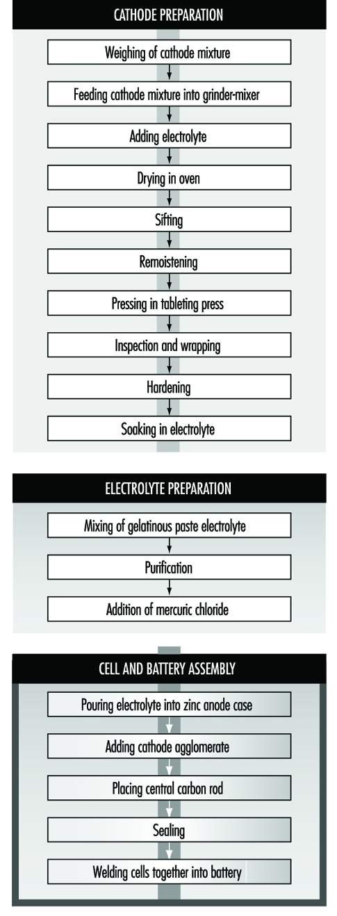
The anode is the zinc case, which is prepared from zinc blanks on a hot press (or zinc sheets are folded and welded to the case). An organic gelatinous paste consisting of maize and flour starches soaked in electrolyte is mixed in large vats. The ingredients are usually poured in from sacks without weighing. The mixture is then purified with zinc chips and manganese dioxide. Mercuric chloride is added to the electrolyte to form an amalgam with the interior of the zinc container. This paste will form the conducting medium or electrolyte.
Cells are assembled by automatic pouring of the required amount of gelatinous paste into the zinc cases to form an inner sleeve lining on the zinc container. In some cases, the cases receive a chromate finish by the pouring in and emptying of a mixture of chromic and hydrochloric acid before adding the gelatinous paste. The cathode agglomerate is then placed in position in the centre of the case. A carbon rod is placed centrally in the cathode to act as the current collector.
The zinc cell is then sealed with molten wax or paraffin and heated with a flame to give a better seal. The cells are then welded together to form the battery. The reaction of the battery is:
2 MnO2 + 2 NH4Cl + Zn → ZnCl2 + H2O2 + Mn2O3
Workers may be exposed to manganese dioxide during weighing, mixer loading, grinding, cleaning the oven, sifting, hand pressing and wrapping, depending on the degree of automation, sealed enclosure and local exhaust ventilation. In manual pressing and wet wrapping, there may be exposure to the wet mixture, which can dry to produce inhalable dust; dermatitis may occur from exposure to the slightly corrosive electrolyte. Personal hygiene measures, gloves and respiratory protection for cleaning and maintenance operations, showering facilities and separate lockers for work and street clothes can reduce these risks. As mentioned above, noise hazards can result from the wrapping and tableting press.
Mixing is automatic during manufacture of the gelatinous paste, and the only exposure is during addition of the materials. During addition of mercuric chloride to the gelatinous paste, there is the risk of inhalation and skin absorption and possible mercury poisoning. LEV or personal protective equipment is necessary.
Exposure to spills of chromic acid and hydrochloric acid during chromating and exposure to welding fumes and fumes from heating the sealing compound are also possible. Mechanization of the chromating process, use of gloves and LEV for heat sealing and welding are suitable precautions.
Nickel-Cadmium Batteries
The most common method today of making nickel-cadmium electrodes is by depositing the active electrode material directly into a porous sintered nickel substrate, or plate. (See figure 3.) The plate is prepared by pressing a paste of sintered grade nickel powder (often made by decomposition of nickel carbonyl) into the open grid of nickel-plated perforated sheet steel (or nickel gauze or nickel-plated steel gauze) and then sintering or drying in an oven. These plates may then be cut, weighed and coined (compressed) for particular purposes or rolled into a spiral for household-type cells.
Figure 3. Nickel-cadmium battery production
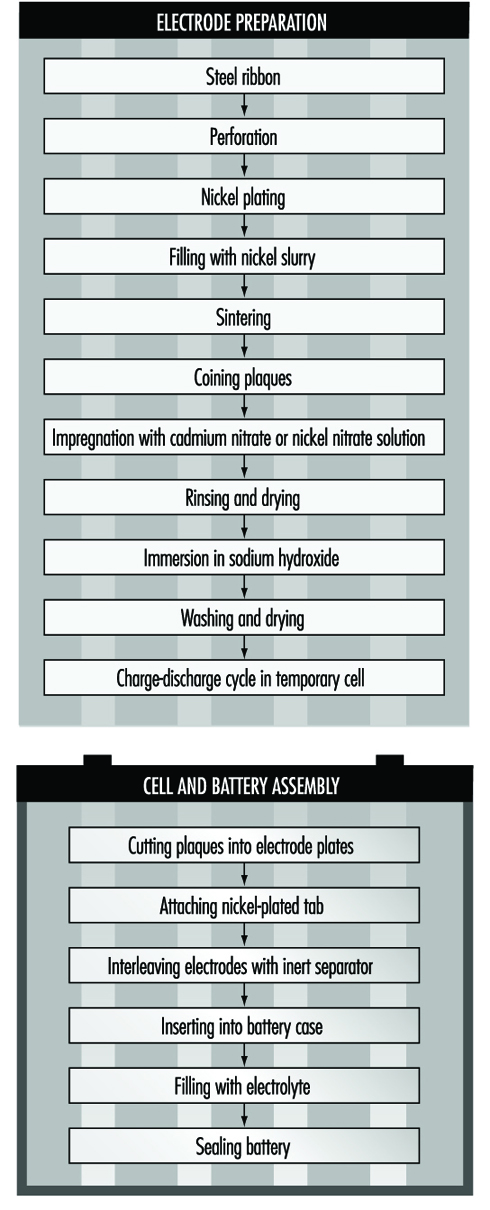
The sintered plaque is then impregnated with nickel nitrate solution for the positive electrode or cadmium nitrate for the negative electrode. These plaques are rinsed and dried, immersed in sodium hydroxide to form nickel hydroxide or cadmium hydroxide and washed and dried again. Usually the next step is to immerse the positive and negative electrodes in a large temporary cell containing 20 to 30% sodium hydroxide. Charge-discharge cycles are run to remove impurities and the electrodes are removed, washed and dried.
An alternative way of making cadmium electrodes is to prepare a paste of cadmium oxide mixed with graphite, iron oxide and paraffin, which is milled and finally compacted between rollers to form the active material. This is then pressed into a moving perforated steel strip that is dried, sometimes compressed, and cut into plates. Lugs may be attached at this stage.
The next steps involve cell and battery assembly. For large batteries, the individual electrodes are then assembled into electrode groups with plates of opposite polarity interleaved with plastic separators. These electrode groups may be bolted or welded together and placed in a nickel-plated steel casing. More recently, plastic battery casings have been introduced. The cells are filled with an electrolyte solution of potassium hydroxide, which may also contain lithium hydroxide. The cells are then assembled into batteries and bolted together. Plastic cells may be cemented or taped together. Each cell is connected with a lead connector to the adjacent cell, leaving a positive and negative terminal at the ends of the battery.
For cylindrical batteries, the impregnated plates are assembled into electrode groups by winding the positive and negative electrodes, separated by an inert material, into a tight cylinder. The electrode cylinder is then placed in a nickel-plated metal case, potassium hydroxide electrolyte is added and the cell is sealed by welding.
The chemical reaction involved in the charging and discharging of nickel-cadmium batteries is:
![]()
The major potential exposure to cadmium occurs from handling of cadmium nitrate and its solution while making paste from cadmium oxide powder and handling the dried active powders. Exposure can also occur during reclamation of cadmium from scrap plates. Enclosure and automated weighing and mixing can reduce these hazards during the early steps.
Similar measures can control exposures to nickel compounds. The production of sintered nickel from nickel carbonyl, although done in sealed machinery, involves potential exposure to extremely toxic nickel carbonyl and carbon monoxide. The process requires continuous monitoring for gas leaks.
The handling of caustic potassium or lithium hydroxide requires suitable ventilation and personal protection. Welding generates fumes and requires LEV.
Health Effects and Disease Patterns
The most serious health hazards in traditional battery making are lead, cadmium, mercury and manganese dioxide exposures. Lead hazards are discussed elsewhere in this chapter and Encyclopaedia. Cadmium can cause kidney disease and is carcinogenic. Cadmium exposure was found to be widespread in US nickel-cadmium battery plants, and many workers have had to be medically removed under the Occupational Safety and Health Administration’s Cadmium Standard provisions due to high cadmium levels in blood and urine (McDiarmid et al. 1996). Mercury affects the kidneys and nervous system. Excessive exposure to mercury vapour has been shown in studies of several mercury battery plants (Telesca 1983). Manganese dioxide exposures have been shown to be high in powder mixing and handling in alkaline dry cell manufacturing (Wallis, Menke and Chelton 1993). This can result in neurofunctional deficits in battery workers (Roels et al. 1992). Manganese dusts can, if absorbed in excessive quantities, lead to disorders of the central nervous system similar to Parkinson’s syndrome. Other metals of concern include nickel, lithium, silver and cobalt.
Skin burns can result from exposure to zinc chloride, potassium hydroxide, sodium hydroxide and lithium hydroxide solutions used in the electrolytes of batteries.
Electric Cable Manufacture
Cables come in a variety of sizes for different uses, from supertension power cables which carry electrical power at more than 100 kilovolts, down to telecommunication cables. The latter in the past utilized copper conductors, but these have been superseded by fibre optic cables, which carry more information in a much smaller cable. In between there are the general cables used for house wiring purposes, other flexible cables and power cables at voltages below those of the supertension cables. In addition, there are more specialized cables such as mineral insulated cables (used where their inherent protection from burning in a fire is crucial—for example, in a factory, in a hotel or on board a ship), enamelled wires (used as electrical windings for motors), tinsel wire (used in the curly connection of a telephone handset), cooker cables (which historically used asbestos insulation but now use other materials) and so on.
Materials and Processes
Conductors
The most common material used as the conductor in cables has always been copper, due to its electrical conductivity. Copper has to be refined to high purity before it can be made into a conductor. The refining of copper from ore or scrap is a two-stage process:
- fire refining in a large furnace to remove unwanted impurities and cast a copper anode
- electrolytic refining in an electrical cell containing sulphuric acid, from which very pure copper is deposited on to the cathode.
In modern plants, copper cathodes are melted in a shaft furnace and continuously cast and rolled into copper rod. This rod is drawn down to the required size on a wire-drawing machine by pulling the copper through a series of precise dies. Historically, the wire-drawing operation was conducted in one central location, with many machines producing wires of different sizes. More recently, smaller autonomous factories have their own, smaller wire-drawing operation. For some specialist applications the copper conductor is plated with a metal coating, such as tin, silver or zinc.
Aluminium conductors are used in overhead power cables where the lighter weight more than compensates for the inferior conductivity compared to copper. Aluminium conductors are made by squeezing a heated billet of aluminium through a die using an extrusion press.
More specialized metallic conductors utilize special alloys for a particular application. A cadmium-copper alloy has been used for overhead catenaries (the overhead conductor used on a railway) and for the tinsel wire used in a telephone handset. The cadmium increases the tensile strength compared to pure copper, and is used so that the catenary does not sag between supports. Beryllium-copper alloy is also used in certain applications.
Optical fibres, consisting of a continuous filament of high optical quality glass to transmit telecommunications, were developed in the early 1980s. This required a totally new manufacturing technology. Silicon tetrachloride is burnt inside a lathe to deposit silicon dioxide on a blank. The silicon dioxide is converted to glass by heating in a chlorine atmosphere; then it is drawn to size, and a protective coating is applied.
Insulation
Many insulation materials have been used on different types of cables. The most common types are plastic materials, such as PVC, polyethylene, polytetrafluoroethylene (PTFE) and poly- amides. In each case, the plastic is formulated to meet a technical specification, and is applied to the outside of the conductor using an extrusion machine. In some instances, materials may be added to the plastic compound for a particular application. Some power cables, for example, incorporate a silane compound for cross-linking the plastic. In cases where the cable is going to be buried in the ground, a pesticide is added to prevent termites from eating the insulation.
Some flexible cables, particularly those in underground mines, use rubber insulation. Hundreds of different rubber compounds are needed to meet different specifications, and a specialist rubber compounding facility is required. The rubber is extruded on to the conductor. It must also be vulcanized by passing through either a bath of hot nitrite salt or a pressurized liquid. To prevent adjacent rubber-insulated conductors from sticking together, they are drawn through talc powder.
The conductor inside a cable may be wrapped with an insulator such as paper (which may have been soaked in a mineral or a synthetic oil) or mica. An outer sheath is then applied, typically by plastic extrusion.
Two methods of manufacturing mineral insulated (MI) cables have been developed. In the first, a copper tube has a number of solid copper conductors inserted into it, and the space between is packed with a magnesium oxide powder. The whole assembly is then drawn down through a series of dies to the required size. The other technique involves continuous welding of a copper spiral around conductors separated by powder. In use, the outer copper sheath of an MI cable is the earth connection, and the inner conductors carry the current. Although no outer layer is needed, some customers specify a PVC sheath for aesthetic reasons. This is counter-productive, since the main advantage of MI cable is that it does not burn, and a PVC sheath negates this advantage somewhat.
In recent years the behaviour of cables in fires has received increasing attention for two reasons:
- Most rubbers and plastics, the traditional insulation materials, emit copious quantities of smoke and toxic gases in a fire, and in a number of high-profile fire incidents this has been the main cause of death.
- Once a cable has burnt through, the conductors touch and fuse the circuit, and so electrical power is lost. This has led to the development of low smoke and fire (LSF) compounds, both for plastic and rubber materials. It should be realized, however, that the best performance in a fire will always be obtained from an MI cable.
A number of specialized materials are used for certain cables. Supertension cables are oil-filled both for insulation and cooling properties. Other cables use a hydrocarbon grease known as MIND, petroleum jelly or a lead sheath. Enamelled wires are typically made by coating them with a polyurethane enamel dissolved in cresol.
Cablemaking
In many cables the individual, insulated conductors are twisted together to form a particular configuration. A number of reels containing the individual conductors revolve around a central axis as the cable is drawn through the machine, in operations known as stranding and lay-up.
Some cables need to be protected from mechanical damage. This is often done by braiding, where a material is interwoven around the outer insulation of a flexible cable such that each strand crosses each other one over and over again in a spiral. An example of such a braided cable (at least in the UK) is that used on electric irons, where textile thread is used as the braiding material. In other cases steel wire is used for the braiding, where the operation is referred to as armouring.
Ancillary operations
Larger cables are supplied on drums of up to a few metres in diameter. Traditionally, drums are wooden, but steel ones have been used. A wooden drum is made by nailing together sawn timber using either a machine or a pneumatic nailing gun. A copper-chrome-arsenic preservative is used to prevent the wood from rotting. Smaller cables are usually supplied on a cardboard reel.
The operation of connecting the two ends of cables together, known as jointing, may well have to be carried out in a remote location. The joint not only has to have a good electrical connection, but must also be able to withstand future environmental conditions. The jointing compounds used are commonly acrylic resins and incorporate both isocyanate compounds and silica powder.
Cable connectors are commonly made out of brass on automatic lathes which manufacture them from bar stock. The machines are cooled and lubricated using a water-oil emulsion. Cable clips are made by plastic injection machines.
Hazards and their Prevention
The most widespread health hazard throughout the cable industry is noise. The noisiest operations are:
- wire-drawing
- braiding
- the copper fire refinery
- continuous casting of copper rods
- cable drum manufacture.
Noise levels in excess of 90 dBA are common in these areas. For wire-drawing and braiding the overall noise level depends upon the number and location of machines and the acoustic environment. The machine layout should be planned to minimize noise exposures. Carefully designed acoustic enclosures are the most effective means of controlling the noise, but are expensive. For the copper fire refinery and continuous casting of copper rods the main sources of noise are the burners, which should be designed for low noise emission. In the case of cable drum manufacture the pneumatically operated nail guns are the principal source of noise, which can be reduced by lowering the air-line pressure and installing exhaust silencers. The industry’s norm in most of the above cases, however, is to issue hearing protection to workers in the areas affected, but such protection will be more uncomfortable than usual due to the hot environments in the copper fire refinery and continuous casting of copper rods. Regular audiometry should also be conducted to monitor each individual’s hearing.
Many of the safety hazards and their prevention are the same as those in many other manufacturing industries. However, special hazards are presented by some cablemaking machines, in that they have numerous reels of conductors rotating around two axes at the same time. It is essential to ensure that machine guards are interlocked to prevent the machine from operating unless the guards are in position to prevent access to running nips and other rotating parts, such as large cable drums. During the initial threading of the machine, when it may well be necessary to permit the operator access inside the machine guard, the machine should be capable of moving only a few centimetres at a time. Interlock arrangements can be achieved by having a unique key which either opens the guard or has to be inserted into the control console to allow it to operate.
An assessment of the risk from flying particles—for example, if a wire breaks and whips out—should be made.
Guards should preferably be designed to physically prevent such particles from reaching the operator. Where this is not possible, suitable eye protection must be issued and worn. Wire-drawing operations are often designated as areas where eye protection must be used.
Conductors
In any hot metal process, such as a copper fire refinery or casting copper rods, water must be prevented from coming into contact with molten metal to prevent an explosion. Loading the furnace can result in the escape of metal oxide fumes into the workplace. This should be controlled using effective local exhaust ventilation over the charging door. Similarly the launders down which the molten metal passes from the furnace to the casting machine and the casting machine itself need to be adequately controlled.
The principal hazard in the electrolytic refinery is the sulphuric acid mist evolved from each cell. Airborne concentrations must be kept below 1 mg/m3 by suitable ventilation to prevent irritation.
When casting copper rods, an additional hazard can be presented by the use of insulation boards or blankets to conserve heat around the casting wheel. Ceramic materials may have replaced asbestos in such applications, but ceramic fibres themselves must be handled with great care to prevent exposures. Such materials become more friable (i.e., easily broken up) after use when they have been affected by heat, and exposures to airborne respirable fibres have resulted from handling them.
An unusual hazard is presented in the manufacture of aluminium power cables. A suspension of graphite in a heavy oil is applied to the ram of the extrusion press to prevent the aluminium billet from sticking to the ram. As the ram is hot, some of this material is burnt off and rises into the roof space. Provided that there is no overhead crane operator in the vicinity and that roof fans are fitted and working, there should be no risk to the health of workers.
Making either cadmium-copper alloy or beryllium-copper alloy can present high risks to the employees involved. Since cadmium boils well below the melting point of copper, freshly generated cadmium oxide fumes will be generated in great quantities whenever cadmium is added to molten copper (which it must be to make the alloy). The process can be carried out safely only with very careful design of the local exhaust ventilation. Similarly the manufacture of beryllium-copper alloy requires great attention to detail, since beryllium is the most toxic of all the toxic metals and has the most stringent of exposure limits.
The manufacture of optical fibres is a highly specialized, high-technology operation. The chemicals used have their own special hazards, and control of the working environment requires the design, installation and maintenance of complex LEV and process ventilation systems. These systems must be controlled by computer-monitored control dampers. The main chemical hazards are from chlorine, hydrogen chloride and ozone. In addition, the solvents used to clean the dies must be handled in extracted fume cabinets, and skin contact with the acrylate-based resins used to coat the fibres must be avoided.
Insulation
Both plastic compounding and rubber compounding operations present particular hazards which must be adequately controlled (see the chapter Rubber Industry). Although the cable industry may use different compounds than other industries, the control techniques are the same.
When they are heated, plastic compounds will give off a complex mixture of thermal degradation products, the composition of which will depend upon the original plastic compound and the temperature to which it is subjected. At the normal processing temperature of plastic extruders, airborne contaminants are usually a relatively small problem, but it is prudent to install ventilation over the gap between the extruder head and the water trough used to cool the product down, mainly to control exposure to the phthalate plasticizers commonly used in PVC. The phase of the operation which may well warrant further investigation is during a changeover. The operator has to stand over the extruder head to remove the still-hot plastic compound, and then run the new compound through (and on to the floor) until only the new colour is coming through and the cable is centralized in the extruder head. It can be difficult to design effective LEV during this phase when the operator is so close to the extruder head.
Polytetrafluoroethylene (PTFE) has its own special hazard. It can cause polymer fume fever, which has symptoms resembling those of influenza. The condition is a temporary one, but should be prevented by adequately controlling exposures to the heated compound.
The use of rubber in making cables has presented a lower level of risk than other uses of rubber, such as in the tyre industry. In both industries the use of an antioxidant (Nonox S) containing β-naphthylamine, up to its withdrawal in 1949, resulted in cases of bladder cancer up to 30 years later in those who had been exposed prior to the withdrawal date, but none in those employed after 1949 only. The cable industry, however, has not experienced the increased incidence of other cancers, particularly of lung and stomach, seen in the tyre industry. The reason is almost certainly that in cable manufacture the extrusion and vulcanizing machines are enclosed, and employee exposures to rubber fumes and rubber dust were generally much lower than in the tyre industry. One exposure of potential concern in rubber cable factories is the use of talc. It is important to ensure that only the non-fibrous form of talc (i.e., one which does not contain any fibrous tremolite) is used and that the talc is applied in an enclosed box with local exhaust ventilation.
Many cables are printed with identification markings. Where modern video jet printers are used the risk to health is almost certainly negligible due to the very small quantities of solvent utilized. Other printing techniques, however, can result in significant solvent exposures, either during normal production, or more usually during cleaning operations. Suitable exhaust systems should therefore be used to control such exposures.
The main hazards from making MI cables are dust exposure, noise and vibration. The first two of these are controlled by standard techniques described elsewhere. Vibration exposure occurred in the past during swaging, when a point was formed at the end of the assembled tube by manual insertion into a machine with rotating hammers, so that the point could be inserted into the drawing machine. More recently this type of swaging machine has been replaced with pneumatic ones, and this has eliminated both the vibration and the noise generated by the older method.
Lead exposure during lead sheathing should be controlled by using adequate LEV and by prohibiting eating, drinking and cigarette smoking in areas liable to be contaminated with lead. Regular biological monitoring should be undertaken by analysing blood samples for lead content at a qualified laboratory.
The cresol used in the manufacture of enamelled wires is corrosive and has a distinctive odour at very low concentrations. Some of the polyurethane is thermally degraded in the enamelling ovens to release toluene di-isocyanate (TDI), a potent respiratory sensitizer. Good LEV is needed around the ovens with catalytic afterburners to ensure that the TDI does not pollute the surrounding area.
Ancillary operations
Jointing operations present hazards to two distinct groups of workers—those that make them and those that use them. Manufacture involves the handling of a fibrogenic dust (silica), a respiratory sensitizer (isocyanate) and a skin sensitizer (acrylic resin). Effective LEV must be used to adequately control employee exposures, and suitable gloves must be worn to prevent skin contact with the resin. The main hazard to users of the compounds is from skin sensitization to the resin. This can be difficult to control since the jointer may not be able to avoid skin contact altogether, and will often be in a remote location away from a source of water for cleaning purposes. A waterless hand cleanser is therefore essential.
Environmental hazards and their prevention
In the main, cable manufacture does not result in significant emissions outside the factory. There are three exceptions to this rule. The first is that exposure to the vapours of solvents used for printing and other purposes are controlled by the use of LEV systems which discharge the vapours to the atmosphere. Such emissions of volatile organic compounds (VOCs) are one of the components necessary to form photochemical smog, and so are coming under increasing pressure from regulatory authorities in a number of countries. The second exception is the potential release of TDI from enamelled wire manufacture. The third exception is that in a number of instances the manufacture of the raw materials used in cables can result in environmental emissions if control measures are not taken. Metal particulate emissions from a copper fire refinery, and from the manufacture of either cadmium-copper or beryllium-copper alloys, should each be ducted to suitable bag filter systems. Similarly any particulate emissions from rubber compounding should be ducted to a bag filter unit. Emissions of particulates, hydrogen chloride and chlorine from the manufacture of optical fibres should be ducted to a bag filter system followed by a caustic soda scrubber.
Electric Lamp and Tube Manufacture
Lamps consist of two basic types: filament (or incandescent) lamps and discharge lamps. The basic components of both lamp types include glass, various metal wire pieces, a fill gas and usually a base. Depending on the lamp manufacturer, these materials are either made in-house or may be obtained from an outside supplier. The typical lamp manufacturer will make its own glass bulbs, but may purchase other parts and glasses from speciality manufacturers or other lamp companies.
Depending on the lamp type, a variety of glasses may be used. Incandescent and fluorescent lamps typically use a soda-lime glass. Higher temperature lamps will use a borosilicate glass, while high-pressure discharge lamps will use either quartz or ceramic for the arc tube and borosilicate glass for the outer envelope. Leaded glass (containing approximately 20 to 30% lead) is typically used for sealing the ends of the lamp bulbs.
The wires used as supports or connectors in lamp construction may be made from a variety of materials including steel, nickel, copper, magnesium and iron, while the filaments are made from tungsten or tungsten-thorium alloy. One critical requirement for the support wire is that it must match the expansion characteristics of the glass where the wire penetrates the glass to conduct the electrical current for the lamp. Frequently, multi-part lead wires are used in this application.
Bases (or caps) are typically made from either brass or aluminium, brass being the preferred material when outdoor use is required.
Filament or Incandescent Lamps
Filament or incandescent lamps are the oldest lamp type still being manufactured. They take their name from the way these lamps produce their light: through the heating of a wire filament to a temperature high enough to cause it to glow. While it is possible to manufacture an incandescent lamp with almost any type of filament (early lamps used carbon), today most such lamps use a filament made of tungsten metal.
Tungsten lamps. The common household version of these lamps consists of a glass bulb enclosing a tungsten wire filament. Electricity is conducted to the filament by wires which support the filament and extend through the glass mount which is sealed to the bulb. The wires are then connected to the metal base, with one wire soldered at the centre eyelet of the base, the other connecting to the threaded shell. The supporting wires are of special composition, so that they have the same expansion characteristics as the glass, preventing leaks when the lamps become hot during use. The glass bulb is typically made from lime glass, while the glass mount is leaded glass. Sulphur dioxide is frequently used in preparing the mount. The sulphur dioxide acts as a lubricant during high-speed lamp assembly. Depending on the design of the lamp, the bulb may enclose a vacuum or may use a fill gas of argon or some other non-reactive gas.
Lamps of this design are sold using clear glass bulbs, frosted bulbs and bulbs coated with a variety of materials. Frosted bulbs and ones coated with a white material (frequently clay or amorphous silica) are used to reduce the glare from the filament found with clear bulbs. The bulbs are also coated with a variety of other decorative coatings, including coloured ceramics and lacquers on the outside of the bulbs and other colours, such as yellow or pink, on the inside of the bulb.
While the typical household shape is the most common, incandescent lamps can be made in many bulb shapes, including tubular, globes and reflector, as well as in many sizes and wattages, from subminiature through to large stage/studio lamps.
Tungsten-halogen lamps. One problem in the design of the standard tungsten filament lamp is that the tungsten evaporates during use and condenses on the cooler glass wall, darkening it and reducing the light transmission. Adding a halogen, such as hydrogen bromide or methyl bromide, to the fill gas eliminates this problem. The halogen reacts with the tungsten, preventing it from condensing on the glass wall. When the lamp cools, the tungsten will re-deposit back on the filament. Since this reaction works best at higher lamp pressures, tungsten-halogen lamps typically contain gas at several atmospheres pressure. Typically the halogen is added as a part of the lamp fill gas, usually at concentrations of 2% or less.
Tungsten-halogen lamps may also use bulbs made from quartz instead of glass. Quartz bulbs can withstand higher pressures than those made from glass. The quartz bulbs present a potential hazard, however, since the quartz is transparent to ultraviolet light. Although the tungsten filament produces relatively little ultraviolet, prolonged exposure at close range can produce reddening of the skin and cause eye irritation. Filtering the light through a cover glass will greatly reduce the amount of ultraviolet, as well as provide protection from the hot quartz in the event the lamp ruptures during use.
Hazards and Precautions
Overall, the greatest hazards in lamp production, regardless of product type, are due to the hazards of automated equipment and the handling of glass bulbs and lamps and other material. Cuts from the glass and reaching into the operating equipment are the most common causes of accidents; material-handling issues, such as repetitive motion or back injuries, are of particular concern.
Lead solder is frequently used on the lamps. For lamps used in higher temperature applications, solders containing cadmium may be used. In automated lamp assembly operations, exposure to both of these solders is minimal. Where hand soldering is done, as in repair or semi-automated operations, the exposures to lead or cadmium should be monitored.
Potential exposures to hazardous materials during lamp manufacturing have consistently decreased since the middle of the 20th century. In incandescent lamp manufacturing, large numbers of the lamps formerly were etched with hydrofluoric acid or bifluoride salt solutions to produce a frosted lamp. This has largely been replaced by the use of a low-toxicity clay coating. While not completely replaced, the use of hydrofluoric acid has been greatly reduced. This change has reduced the risk of burns to the skin and lung irritation due to the acid. The ceramic coloured coatings used on the outside of some lamp products formerly contained heavy metal pigments such as lead, cadmium, cobalt and others, as well as using a lead silicate glass frit as part of the composition. During recent years, many of the heavy metal pigments have been replaced by less toxic colourants. In cases where the heavy metals are still used, a lower toxicity form may be used (e.g., chromium III instead of chromium VI).
Coiled tungsten filaments continue to be made by wrapping the tungsten around a molybdenum or a steel mandrel wire. Once the coil has been formed and sintered, the mandrels are dissolved using either hydrochloric acid (for the steel) or a mixture of nitric and sulphuric acid for the molybdenum. Due to the potential acid exposures, this work is routinely done in hood systems or, more recently, in totally enclosed dissolvers (especially where the nitric/sulphuric mix is involved).
The fill gasses used in tungsten-halogen lamps are added to the lamps in totally enclosed systems with little loss or exposure. Hydrogen bromide use presents its own problems due to its corrosive nature. LEV must be provided, and corrosion-resistant piping must be used for the gas delivery systems. Thoriated tungsten wire (usually 1 to 2% thorium) is still used in some lamp types. However, there is little risk from the thorium in the wire form.
Sulphur dioxide must be carefully controlled. LEV should be used wherever the material is added to the process. Leak detectors may also be useful in storage areas. Use of smaller 75-kg gas cylinders is preferred over larger 1,000-kg containers due to the potential consequences of a catastrophic release.
Skin irritation can be a potential hazard from either the soldering fluxes or from the resins used in the basing cement. Some basing cement systems use paraformaldehyde instead of natural resins, resulting in potential formaldehyde exposure during curing of the basing cement.
All lamps use a chemical “gettering” system, in which a material is coated on the filament prior to assembly. The purpose of the getter is to react with and scavenge any residual moisture or oxygen in the lamp after the lamp is sealed. Typical getters include phosphorus nitride and mixtures of aluminium and zirconium metal powders. While the phosphorus nitride getter is fairly benign in use, handling aluminium and zirconium metal powders can be a flammability hazard. The getters are applied wet in an organic solvent, but if the material is spilled, the dry metal powders can be ignited by friction. Metal fires must be extinguished with special Class D fire extinguishers and cannot be fought with water, foam or other usual materials. A third type of getter includes use of phosphine or silane. These materials can be included in the gas fill of the lamp at low concentration or can be added at high concentration and “flashed” in the lamp prior to the final gas fill. Both these materials are highly toxic; if used at high concentration, totally enclosed systems with leakage detectors and alarms should be used at the site.
Discharge Lamps and Tubes
Discharge lamps, both low- and high-pressure models, are more efficient on a light per watt basis than incandescent lamps. Fluorescent lamps have been used for many years in commercial buildings and have been finding increased use in the home. Recently, compact versions of the fluorescent lamp have been developed specifically as replacements for the incandescent lamp.
High-pressure discharge lamps have long been used for large area and street lighting. Lower-wattage versions of these products are also being developed.
Fluorescent lamps
Fluorescent lamps are named for the fluorescent powder used to coat the inside of the glass tube. This powder absorbs ultraviolet light produced by the mercury vapour used in the lamp, and converts and re-emits it as visible light.
The glass used in this lamp is similar to that used in incandescent lamps, using lime glass for the tube and leaded glass for the mounts on each end. Two different families of phosphors are in use currently. Halophosphates, based on either calcium or strontium chloro-fluoro-phosphate, are the older phosphors, coming into wide use in the early 1950s when they replaced phosphors based on beryllium silicate. The second phosphor family includes phosphors made from rare earths, typically including yttrium, lanthanum and others. These rare-earth phosphors typically have a narrow emission spectrum, and a mixture of these are used—generally a red, a blue and a green phosphor.
The phosphors are mixed with a binder system, suspended in either an organic mix or a water/ammonia mixture and coated on the inside of the glass tube. The organic suspension uses butyl acetate, butyl acetate/naphtha or xylene. Due to environmental regulations, water-based suspensions are replacing those that are organic based. Once the coating is applied, it is dried onto the tube, and the tube is heated to a high temperature to remove the binder.
One mount is attached to each end of the lamp. Mercury is now introduced into the lamp. This can be done in a variety of ways. Although in some areas the mercury is added manually, the predominant way is automatically, with the lamp mounted either vertically or horizontally. On vertical machines, the mount stem on one end of the lamp is closed. Then mercury is dropped into the lamp from above, the lamp is filled with argon at low pressure, and the top mount stem is sealed, completely sealing the lamp. On horizontal machines, the mercury is introduced from one side, while the lamp is exhausted from the other side. Argon is again added to the proper pressure, and both ends of the lamp are sealed. Once sealed, the caps or bases are added to the ends, and the wire leads are then either soldered or welded to the electrical contacts.
Two other possible ways of introducing mercury vapour can be used. In one system, the mercury is contained on a mercury-impregnated strip, which releases the mercury when the lamp is first started. In the other system, liquid mercury is used, but it is contained within a glass capsule which is attached to the mount. The capsule is ruptured after the lamp has been sealed and exhausted, thereby releasing the mercury.
Compact fluorescent lamps are smaller versions of the standard fluorescent lamp, sometimes including the ballast electronics as an integral component of the lamp. Compact fluorescents generally will use a mixture of rare-earth phosphors. Some compact lamps will incorporate a glow starter containing small amounts of radioactive materials to aid in starting the lamp. These glow starters typically use krypton-85, hydrogen-3, promethium-147 or natural thorium to provide what is called a dark current, which helps the lamp start quicker. This is desirable from a consumer standpoint, where the customer wants the lamp to start immediately, without flickering.
Hazards and precautions
Fluorescent lamp manufacturing has seen a considerable number of changes. Early use of a beryllium-containing phosphor was discontinued in 1949, eliminating a significant respiratory hazard during phosphor production and use. In many operations, water-based phosphor suspensions have replaced organic suspensions in the coating of the fluorescent lamps, reducing exposure to the workers as well as reducing the emission of VOCs to the environment. Water-based suspensions do involve some minimal exposure to ammonia, particularly during mixing of the suspensions.
Mercury remains the material of greatest concern during fluorescent lamp making. While the exposures are relatively low except around the exhaust machines, there is potential for significant exposure to workers stationed around the exhaust machine, to mechanics working on these machines and during clean-up operations. Personal protective equipment, such as coveralls and gloves to avoid or limit exposure and, where needed, respiratory protection, should be used, especially during maintenance activities and clean-up. A biological monitoring programme, including mercury urinalysis, should be established for fluorescent lamp manufacturing sites.
The two phosphor systems currently in production utilize materials considered to have relatively low toxicity. While some of the additives to the parent phosphors (such as barium, lead and manganese) have exposure limits established by various governmental agencies, these components are usually present in relatively low percentages in the compositions.
Phenol-formaldehyde resins are used as electrical insulators in the end caps of the lamps. The cement typically includes natural and synthetic resins, which may include skin irritants such as hexamethylene-tetramine. Automated mixing and handling equipment limits the potential for skin contact to these materials, thereby limiting the potential for skin irritation.
High-pressure mercury lamps
High-pressure mercury lamps include two similar types: those using just mercury and those using a mixture of mercury and a variety of metal halides. The basic design of the lamps is similar. Both types use a quartz arc tube which will contain the mercury or mercury/halide mixture. This arc tube is then enclosed in a hard, borosilicate glass outer jacket, and a metal base is added to provide for electrical contacts. The outer jacket can be clear or coated with either a diffusing material or a phosphor to modify the colour of the light.
Mercury lamps contain only mercury and argon in the quartz arc tube of the lamp. The mercury, under high pressure, generates light with a high blue and ultraviolet content. The quartz arc tube is completely transparent to UV light, and in the event that the outer jacket is broken or removed, is a powerful UV light source that can produce skin and eye burns in those exposed. Though the typical mercury lamp design will continue to operate if the outer jacket is removed, manufacturers also offer some models in a fused design which will stop operating if the jacket is broken. During normal use, the borosilicate glass of the outer jacket absorbs a high percentage of the UV light, so that the intact lamp does not pose a hazard.
Because of the high blue content of the mercury lamp spectrum, the inside of the outer jacket is frequently coated with a phosphor such as yttrium vanadate phosphate or similar red-enhancing phosphor.
Metal halide lamps also contain mercury and argon in the arc tube, but add metal halides (typically a mixture of sodium and scandium, possibly with others). The addition of the metal halides enhances the red light output of the lamp, producing a lamp which has a more balanced light spectrum.
Hazards and precautions
Other than mercury, potentially hazardous materials used in high-pressure mercury lamp production include the coating materials used on the outer envelopes and the halide additives used in the metal halide lamps. One coating material is a simple diffuser, the same as that used in incandescent lamps. Another is a colour-correcting phosphor, yttrium vanadate or yttrium vanadate phosphate. While similar to vanadium pentoxide, the vanadate is considered to be less toxic. Exposure to the halide materials is normally not significant, since the halides react in moist air and must be kept dry and under an inert atmosphere during handling and use. Similarly, although the sodium is a highly reactive metal, it too needs to be handled under an inert atmosphere to avoid oxidizing the metal.
Sodium Lamps
Two types of sodium lamps are currently produced. Low-pressure lamps contain only metallic sodium as the light emitting source and produce a highly yellow light. High-pressure sodium lamps use mercury and sodium to generate a whiter light.
Low-pressure sodium lamps have one glass tube, which contains the metallic sodium, enclosed within a second glass tube.
High-pressure sodium lamps contain a mixture of mercury and sodium within a high-purity ceramic alumina arc tube. Other than the composition of the arc tube, the construction of the high-pressure sodium lamp is essentially the same as the mercury and metal halide lamps.
Hazards and precautions
There are few unique hazards during manufacturing of high- or low-pressure sodium lamps. In both lamp types, the sodium must be kept dry. Pure metallic sodium will violently react with water, producing hydrogen gas and enough heat to cause ignition. Metallic sodium left out in air will react with the moisture in the air, producing an oxide coating on the metal. To avoid this, the sodium is usually handled in a glove box, under a dry nitrogen or argon atmosphere. For sites manufacturing high-pressure sodium lamps, additional precautions are needed to handle the mercury, similar to those sites manufacturing high-pressure mercury lamps.
Environmental and Public Health Issues
Waste disposal and/or recycling of mercury-containing lamps is an issue that has received a high degree of attention in many areas of the world over the last several years. While at best a “break even” operation from a cost viewpoint, technology currently exists to reclaim the mercury from fluorescent and high-pressure discharge lamps. Recycling of lamp materials at the present time is more accurately described as reclamation, since the lamp materials are rarely reprocessed and used in making new lamps. Typically, the metal parts are sent to scrap metal dealers. The recovered glass may be used to make fibreglass or glass blocks or used as aggregate in cement or asphalt paving. Recycling may be the lower-cost alternative, depending on location and availability of recycling and hazardous or special waste disposal options.
The ballasts used in fluorescent lamp installations previously contained capacitors which used PCBs as the dielectric. While manufacture of PCB-containing ballasts has been discontinued, many of the older ballasts may still be in use due to their long life expectancy. Disposal of the PCB-containing ballasts may be regulated and may require disposal as a special or hazardous waste.
Glass manufacturing, particularly borosilicate glasses, can be a significant source of NOx emission to the atmosphere. Recently, pure oxygen instead of air has been used with gas burners as a means of reducing the NOx emissions.
Domestic Electrical Appliance Manufacture
Adapted from 3rd edition, Encyclopaedia of Occupational Health and Safety.
The domestic electrical appliance industry is responsible for the manufacture of a wide-ranging variety of equipment including appliances designed for audio-visual, cooking, heating, food preparation and storage (refrigeration) uses. The production and manufacture of such appliances involve many highly-automated processes which can have associated health hazards and disease patterns.
Manufacturing Processes
Materials used in the manufacture of domestic electrical appliances can be categorized into:
- metals which are used typically for electric conductors in cables and appliance structure and/or framework
- dielectrics or insulating materials used for prevention of accidental contact with live electrical equipment
- paints and finishes
- chemicals.
Examples of the materials included in the four categories referred to are shown in table 1.
Table 1. Examples of materials used in the manufacture of domestic electrical appliances
|
Metals |
Dielectrics |
Paints/finishes |
Chemicals |
|
Steel |
Inorganic materials (e.g., mica) |
Paints |
Acids |
|
Aluminium |
Plastics (e.g., PVC) |
Lacquers |
Alkalis |
|
Lead |
Rubber |
Varnishes |
Solvents |
|
Cadmium |
Silico-organic materials |
Corrosion-resistant treatments |
|
|
Mercury |
Other polymers (e.g., nylon) |
Note: Lead and mercury are decreasingly common in domestic electrical appliance manufacturing
The materials used in the domestic electrical appliance industry must satisfy exacting requirements, including the ability to withstand the handling likely to be encountered in normal operation, the ability to withstand metal fatigue and the ability to be unaffected by any other processes or treatment which could render the appliance dangerous to use either immediately or after a prolonged period of time.
The materials used in the industry will often be received at the appliance assembly stage having already undergone several manufacturing processes, each of which is likely to have its own hazards and health problems. Details of these hazards and problems are considered under the appropriate chapters elsewhere in this Encyclopaedia.
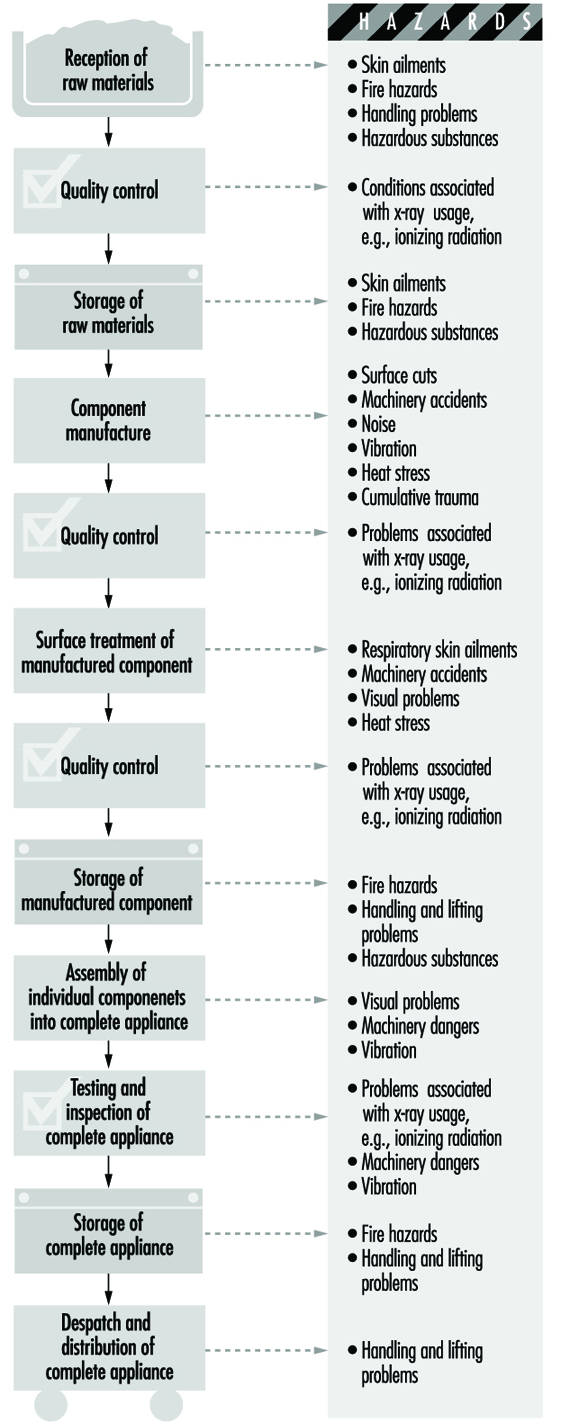
The manufacturing processes will vary from product to product, but in general will follow the production flow shown in figure 1. This chart also shows the hazards associated with the different processes.
Figure 1. Manufacturing process sequence & hazards
Health and Safety Issues
Fire and explosion
Many of the solvents, paints and insulating oils used in the industry are flammable substances. These materials should be stored in suitable cool, dry premises, preferably in a fireproof building separate from the production facility. Containers should be clearly labelled and different substances well separated or stored apart as required by their flashpoints and their class of risk. In the case of insulating materials and plastics, it is important to obtain information on the combustibility or fire characteristics of each new substance used. Powdered zirconium, which is now used in significant quantities in the industry, is also a fire hazard.
The quantities of flammable substances issued from storerooms should be kept to the minimum required for production. When flammable liquids are being decanted, charges of static electricity may form, and consequently all containers should be grounded. Fire-extinguishing appliances must be provided and the personnel of the storeplace instructed in their use.
Painting of components is usually carried out in specially built paint booths, which must have adequate exhaust and ventilation equipment that, when used with personal protective equipment (PPE), will create a safe working environment.
During welding, special fire precautions should be taken.
Accidents
Reception, storage and dispatch of raw materials, components and finished products can give rise to accidents involving trips and falls, falling objects, fork trucks and so forth. Manual materials handling can also create ergonomic problems which can be alleviated by automation whenever possible.
Since numerous different processes are employed in the industry, the accident hazards will vary from shop to shop in the plant. During component production there will be machine hazards in the use of machine tools, power presses, plastics injection-moulding machines and so on, and efficient machinery guarding is essential. During electroplating, precautions must be taken against splashes of corrosive chemicals. During component assembly, the constant movement of components from one process to another means that the danger of accidents due to in-plant transport and mechanical handling equipment is high.
Quality testing does not give rise to any special safety problems. However, performance testing requires special precautions since the tests are often carried out on semi-finished or uninsulated appliances. During electrical testing, all live components, conductors, terminals and measuring instruments should be protected to prevent accidental contact. The workplace should be screened off, entrance of unauthorized persons prohibited and warning notices posted. In electrical testing areas, the provision of emergency switches is particularly advisable, and the switches should be in a prominent position so that in an emergency all equipment can be immediately de-energized.
For testing appliances that emit x rays or contain radioactive substances, there are radiation protection regulations. A competent supervisor should be made responsible for observance of the regulations.
There are special risks in the use of compressed gases, welding equipment, lasers, impregnation plant, spray-painting equipment, annealing and tempering ovens and high-voltage electrical installations.
During all repair and maintenance activities, adequate lockout/tagout programmes are essential.
Health Hazards
Occupational diseases associated with the manufacture of domestic electrical equipment are relatively low in number and not normally considered to be severe. Such problems that do exist are typified by:
- the development of skin conditions due to the use of solvents, cutting oils, hardeners used with epoxy resin and polychlorinated biphenyls (PCBs)
- the onset of silicosis due to the inhalation of silica in sandblasting (although sand is being increasingly replaced by less toxic blasting agents such as corundum, steel grit or shot)
- health problems due to inhalation of solvent vapours in painting and degreasing, and lead poisoning from use of lead pigments, enamels, etc.
- varying levels of noise produced during the processes.
Wherever possible, highly toxic solvents and chlorinated compounds should be replaced by less dangerous substances; under no circumstances should benzene or carbon tetrachloride be employed as solvents. Lead poisoning may be overcome by substitution of safer materials or techniques and the strict application of safe working procedures, personal hygiene and medical supervision. Where there is a danger of exposure to hazardous concentrations of atmospheric contaminants, the workplace air should be regularly monitored, and appropriate measures such as the installation of an exhaust system taken where necessary. The noise hazard may be reduced by enclosure of noise sources, the use of sound-absorbent materials in workrooms or the use of personal hearing protection.
Safety engineers and industrial physicians should be called upon at the design and planning stage of new plants or operations, and the hazards of processes or machines should be eliminated before processes are started up. This should be followed up by regular inspection of machines, tools, plant, transport equipment, firefighting appliances, workshops and test areas and so on.
Worker participation in the safety effort is essential, and supervisors should ensure that personal protective equipment is available and worn where necessary. Particular attention should be paid to the safety training of new workers, since these account for a relatively high proportion of accidents.
Workers should receive a pre-placement medical examination and, where there is the possibility of hazardous exposure, periodic examination as necessary.
Many processes in the production of individual components will involve the rejection of waste material (e.g., “swarf” from sheet or bar metal), and the disposal of such materials must be in accordance with safety requirements. Furthermore, if such process waste cannot be returned to the producer or manufacturer for recycling, then its subsequent disposal must be by approved processes in order to avoid environmental pollution.
Environmental and Public Health Issues
The main environmental problems associated with electrical appliance and equipment manufacture involve pollution and treatment of materials discarded during the manufacturing processes, together with the recycling, where possible, of the complete product when it has reached the end of its life.
Batteries
The exhaust of air contaminated with acid, alkali, lead, cadmium and other potentially harmful materials into the atmosphere and the pollution of water from the manufacturing of batteries should be prevented as far as possible, and where this is not possible it should be monitored to ensure compliance with relevant legislation.
The use of batteries can generate public health concerns. Leaking lead-acid or alkaline batteries can result in burns from the electrolyte. Recharging large lead-acid batteries can produce hydrogen gas, a fire and explosion hazard in enclosed areas. Release of thionyl chloride or sulphur dioxide from large lithium batteries can involve exposure to sulphur dioxide, hydrochloric acid mist, burning lithium and so on, and has caused at least one fatality (Ducatman, Ducatman and Barnes 1988). This could also be a hazard during manufacture of these batteries.
Battery manufacturers have become aware of increasing environmental concern from the disposal of batteries containing toxic heavy metals by putting them in landfills or incinerating them with other garbage. Leakage of toxic metals from waste dumps or alternatively escaping from the chimneys of waste incinerators can result in water and air contamination. The manufacturers therefore recognized the need to reduce the mercury content of batteries, in particular, within the limits allowable by modern technology. The campaign for mercury elimination commenced in advance of the legislation introduced in the European Union, the EC Battery Directive.
Recycling is another way to deal with environmental pollution. Nickel-cadmium batteries can be recycled relatively easily. The recovery of cadmium is very efficient and it is re-used in the construction of nickel-cadmium batteries. The nickel will subsequently be used in the steel industry. The initial economics suggested that the recycling of nickel-cadmium batteries was not cost effective, but advances in technology are expected to improve the situation. Mercuric oxide cells, which are covered by the EC Battery Directive, have been used primarily in hearing aids, and are being replaced typically with lithium or zinc-air batteries. Silver oxide cells are recycled, especially by the jewellery industry, due to the value of the silver content.
When recycling harmful materials, care has to be taken similar to that exercised during the manufacturing processes. During the recycling of silver batteries, for example, workers may be exposed to mercury vapour and silver oxide.
The repair and recycling of lead-acid batteries can result not only in lead poisoning among the workers, and sometimes their families, but also in extensive lead contamination of the environment (Matte et al. 1989). In many countries, particularly in the Caribbean and Latin America, lead car battery plates are burned to produce lead oxide for pottery glazes.
Electric Cable Manufacture
Electric cable manufacture has three major sources of pollution: solvent vapours, potential release of toluene di-isocyanate from enamelled wire manufacture and environmental emissions during the manufacture of materials used in cables. All of these require appropriate environmental controls.
Electric Lamp and Tube Manufacture
The major environmental concerns here are the waste disposal and/or recycling of mercury-containing lamps and the disposal of PCBs from the ballasts of fluorescent lamps. Glass manufacturing can also be a significant source of emission of nitrogen oxides into the atmosphere.
Domestic Electric Appliances
Since the electric appliance industry is to a large extent an assembly industry, environmental issues are minimal, with the major exception being paints and solvents used as surface coatings. Standard pollution control measures should be instituted in accordance with environmental regulations.
The recycling of electrical appliances involves separation of the recovered equipment into different materials such as copper and mild steel which can be reused, which is discussed elsewhere in this Encyclopaedia.
" DISCLAIMER: The ILO does not take responsibility for content presented on this web portal that is presented in any language other than English, which is the language used for the initial production and peer-review of original content. Certain statistics have not been updated since the production of the 4th edition of the Encyclopaedia (1998)."