- You are here:
-
Home

-
Contents
-
Part XIII. Manufacturing Industries
- Glass, Pottery and Related Materials

84. Glass, Pottery and Related Materials
Chapter Editors: Joel Bender and Jonathan P. Hellerstein
Table of Contents
Tables and Figures
Glass, Ceramics and Related Materials
Jonathan P. Hellerstein, Joel Bender, John G. Hadley and Charles M. Hohman
Case Study: Optical Fibres
George R. Osborne
Case Study: Synthetic Gems
Basil Dolphin
Tables
Click a link below to view table in the article context.
1. Typical body constituents
2. Manufacturing processes
3. Selected chemical additives
4. Refractory usage by industry in the USA
5. Potential health & safety hazards
6. Nonfatal occupational injury & illness
Figures
Point to a thumbnail to see figure caption, click to see figure in article context.


Glass, Ceramics and Related Materials
This chapter covers the following product sectors:
- glass
- synthetic vitreous fibres
- pottery
- ceramic tile
- industrial ceramics
- brick and tile
- refractories
- synthetic gems
- optical fibres.
Interestingly, not only do most of these sectors have roots in antiquity, but they also share a number of common general processes. For example, all are fundamentally based on the use of naturally occurring raw materials in powder or fine particulate form which are transformed by heat into the desired products. Therefore, despite the range of processes and products encompassed in this group, these common processes allow a common overview of potential health hazards associated with these industries. Since the various manufacturing sectors are composed of both small, fragmented segments (e.g., brick manufacturing) and large, technically sophisticated manufacturing plants employing thousands of workers, each sector is described separately.
Common Processes and Hazards
There are common safety and health hazards encountered in manufacturing of products in these business sectors. The hazards and control measures are discussed in other sections of the Encyclopaedia. Process-specific hazards are discussed in the individual sections of this chapter.
Batch raw material processes
Most of the industrial manufacturing processes receive dry solid raw materials in bulk form or individual bags. Bulk solid raw materials are unloaded from hopper rail cars or over-the-road trucks into bins, hoppers or mixers by gravity, pneumatic transfer lines, screw conveyors, bucket conveyors or other mechanical transfer. Pallets of bagged raw materials (20 to 50 kg) or large bulk fabric bag containers (0.5 to 1.0 tonnes) are unloaded from truck trailers or rail boxcars by powered industrial lift trucks, cranes or hoists. Individual bags or raw materials are removed from pallets manually or with powered lift assists. Bagged raw materials are typically charged into a bag dumping station or directly into storage hoppers or scale hoppers.
Potential safety and health hazards associated with the solid raw material unloading, handling and transfer processes include:
- noise exposures in the 85 to 100 dBA range. Pneumatic vibrators, compressors, valve actuators, mixing drive motors, blowers, and dust collectors are some major noise sources.
- exposures to respirable airborne particulate from the transfer and mixing of granular solid raw materials. Exposures depend on composition of raw materials but may commonly include silica (SiO2), clay, alumina, limestone, alkaline dusts, metal oxides, heavy metals and nuisance particulate.
- ergonomic hazards associated with manual lifting or handling of raw material bags, vibrators, or transfer lines and system maintenance activities
- physical hazards from manoeuvring rail cars or trucks, powered-industrial truck traffic, work at elevated heights, confined-space entries and contact with electrical, pneumatic or mechanical energy sources—e.g., nip points, rotating parts, drive gears, shafts, belts and pulleys.
Firing or melting processes
Manufacturing products in these business sectors involves drying, melting or firing processes in kilns or furnaces. The heat for these processes is generated by combustion of propane, natural gas (methane) or fuel oil, electric arc melting, microwave, dielectric drying and/or resistance heating with electricity. Potential hazards presented from firing or melting processes include:
- exposures to combustion products such as carbon monoxide, nitrogen oxides (NOx) and sulphur dioxide
- fumes and particulates from airborne raw materials (e.g., silica, metals, alkaline dusts) or by-products (e.g., hydrogen fluoride, cristobalite, heavy metal fumes)
- fire or explosion associated with fuel systems used for process heat or fuel for lift trucks; potential fire or explosion hazards associated with flammable fuel storage tanks, piping distribution systems and vaporizers. Back-up or stand-by fuel systems in-frequently used for natural gas curtailments can present similar fire or explosion concerns.
- infrared radiation exposure from molten material, which can increase risk of heat cataracts or skin burns
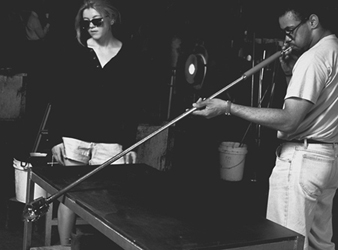
- radiant energy and heat stress. The working environment around furnaces or kilns can be extremely hot. Significant heat stress problems can occur when emergency repair work or routine maintenance is performed near or above firing or melting processes. Severe thermal burns can result from direct skin contact with hot surfaces or molten materials (see figure 1).
Figure 1. Quality-control technician
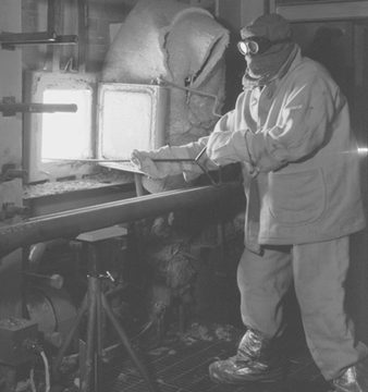
- electrical energy hazards. Direct contact with high-voltage electric energy used for resistance heating to supplement fuel-fired processes presents an electrocution hazard and possible health concerns about exposure to electromagnetic fields (EMF). Strong magnetic and electric fields can potentially interfere with pacemakers and other implanted medical devices.
- noise exposures above 85 to 90 dBA from combustion blowers, batch hoppers or mixers, feed processes and conveyors.
handling in production, fabrication, packaging and warehousing
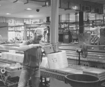
Material-handling, fabrication and packaging processes differ to a large extent in this business sector, as do the size, shape and weights of products. The high density of materials in this sector or bulky configurations present common material-handling hazards. Manual lifting and material handling in production, fabrication, packaging and warehousing in this industry accounts for many disabling injuries. (See “Injury and illness profile” section below.) Injury reduction efforts are focusing on reducing manual lifting and material handling. For example, innovative packaging designs, robotics for stacking and palletizing finished products, and automatic guided transport vehicles for warehousing are starting to be used in select parts of this business sector to eliminate manual material handling and associated injuries. Use of conveyors, manned lift assists (e.g., vacuum hoists) and scissors platforms for handling and palletizing products are currently common material-handling practices (see figure 2).
Figure 2. Vacuum lift assist being used
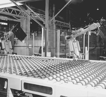
The use of robotics to eliminate manual material handling is playing a major role in prevention of ergonomic injuries. Robotics has reduced ergonomic stresses and severe laceration injuries that have been historically associated with material handling (e.g., flat glass) in the production workforce (see figure 3). However, increased utilization of robotics and process automation introduces moving machinery and electric power hazards, which transforms the types of hazards and also transfers risks to other workers (from production to maintenance workers). Proper designs of electronic controls and logic sequencing, machine guards, total energy lockout practices and establishing safe operating and maintenance procedures are fundamental ways to control injuries to maintenance and production workers.
Figure 3. Robotics used in plate-glass
Rebuilds and reconstruction activities
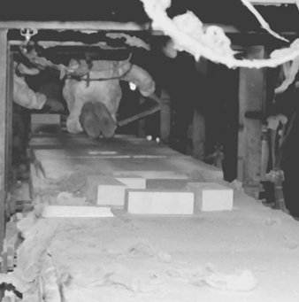
Numerous potential health and safety hazards are encountered during periodic major rebuilds or cold repairs to furnaces or kilns. A wide range of hazards associated with construction activities may be encountered. Examples include: ergonomic hazards with material handling (e.g., refractory bricks); airborne exposures to silica, asbestos, refractory ceramic fibres or particulate matter containing heavy metal, during demolition, or by-products of cutting and welding; heat stress; work at elevated heights; slip, trip or fall hazards; confined-space hazards (see figure 4); and contact with hazardous energy sources.
Figure 4. Confined-space entry
Glass
General profile
Glass was formed naturally from common elements in the earth’s crust long before anyone ever thought of experimenting with its composition, moulding its shape or putting it to the myriad of uses that it enjoys today. Obsidian, for instance, is a naturally occurring combination of oxides fused by intense volcanic heat and vitrified (made into a glass) by rapid air cooling. Its opaque, black colour comes from the relatively high amounts of iron oxide it contains. Its chemical durability and hardness compare favourably with many commercial glasses.
Glass technology has evolved for 6,000 years, and some modern principles date back to ancient times. The origin of the first synthetic glasses is lost in antiquity and legend. Faience was made by the Egyptians, who molded figurines from sand (SiO2), the most popular glass-forming oxide. It was coated with natron, the residue left by the flooding Nile river, which was composed principally of calcium carbonate (CaCO3), soda ash (Na2CO3), salt (NaCl) and copper oxide (CuO). Heating below 1,000 °C produced a glassy coating by the diffusion of the fluxes, CaO and Na2O into the sand and their subsequent solid-state reaction with the sand. The copper oxide gave the article an appealing blue colour.
According to the definition given by Morey: “Glass is an inorganic substance in a condition which is continuous with, and analogous to, the liquid state of that substance, but which, as the result of a reversible change in viscosity during cooling, has attained so high a degree of viscosity as to be, for all practical purposes, rigid.” ASTM defines glass as “an inorganic product of fusion that has cooled to a rigid condition without crystallizing.” Both organic and inorganic materials may form glasses if their structure is non-crystalline—that is, if they lack long-range order.
A most important development in glass technology was the use of a blow pipe (see figure 5), which was first used in approximately 100 years BC. From then onwards, there was a rapid development in the technique of manufacturing glass.
Figure 5. The blow pipe
The first glass was coloured because of the presence of various impurities such as oxides of iron and chromium. Virtually colourless glass was first made some 1,500 years ago.
At that time glass manufacturing was developing in Rome, and from there it moved to many other countries in Europe. Many glass works were built in Venice, and an important development took place there. In the 13th century, many of the glass plants were moved from Venice to a nearby island, Murano. Murano is still a centre for the production of hand-made glass in Italy.
By the 16th century, glass was made all over Europe. Now Bohemian glass from the Czech Republic is well known for its beauty and glass plants in the United Kingdom and Ireland produce high-quality lead crystal glass tableware. Sweden is another country that is home to artistic glass crystalware production.
In North America the first manufacturing establishment of any sort was a glass factory. English settlers started to produce glass at the beginning of the 17th century at Jamestown, Virginia.
Today glass is manufactured in most countries all over the world. Many products of glass are made in fully automatic processing lines. Although glass is one of the oldest materials, its properties are unique and not yet fully understood.
The glass industry today is made up of several major market segments, which include the flat glass market, the consumer houseware market, the glass containers market, the optical glass industry and the scientific glassware market segment. The optical and scientific glass markets tend to be very ordered and are dominated by one or two suppliers in most countries. These markets are also much lower in volume than the consumer-based markets. Each of these markets has developed over the years by innovations in specific glass technology or manufacturing advancements. The container industry, for example, was driven by the development of high-speed bottle-making machines developed in the early 1900s. The flat glass industry was significantly advanced by the development of the float glass process in the early 1960s. Both of these segments are multi-billion-dollar businesses worldwide today.
Glass housewares fall into four general categories:
- tableware (including dinnerware, cups and mugs)
- drinkware
- bakeware (or ovenware)
- top-of-stove cookware.
While worldwide estimates are difficult to obtain, the market for glass housewares is undoubtedly on the order of US$1 billion in the United States alone. Depending upon the specific category, a variety of other materials compete for market share, including ceramics, metals and plastics.
Manufacturing processes
Glass is an inorganic product of fusion which has cooled to a rigid condition without crystallizing. Glass is typically hard and brittle and has a conchoidal fracture. Glass may be manufactured to be coloured, translucent or opaque by varying the dissolved amorphous or crystalline materials that are present.
When glass is cooled from the hot molten state, it gradually increases in viscosity without crystallization over a wide temperature range, until it assumes its characteristic hard, brittle form. Cooling is controlled to prevent crystallization, or high strain.
While any compound which has these physical properties is theoretically a glass, most commercial glasses fall into three main types and have a wide range of chemical compositions.
- Soda-lime-silica glasses are the most important glasses in terms of quantity produced and variety of use, including almost all flat glass, containers, low-cost mass-produced domestic glassware and electric light bulbs.
- Lead-potash-silica glasses contain a varying but often high proportion of lead oxide. Optical glass manufacture makes use of the high refractive index of this type of glass; hand-blown domestic and decorative glassware makes use of its ease of cutting and polishing; electrical and electronic applications takes advantage of its high electrical resistivity and radiation protection.
- Borosilicate glasses have a low thermal expansion and are resistant to thermal shock, which makes them ideal for domestic oven and laboratory glassware and for glass fibre for plastic reinforcements.
A commercial glass batch consists of a mixture of several ingredients. However, the largest fraction of the batch is made up of from 4 to 6 ingredients, chosen from such materials as sand, limestone, dolomite, soda ash, borax, boric acid, feldspathic materials, lead and barium compounds. The remainder of the batch consists of several additional ingredients, chosen from a group of some 15 to 20 materials commonly referred to as minor ingredients. These latter additions are added with a view to providing some specific function or quality, such as colour, which is to be realized during the glass preparation process.
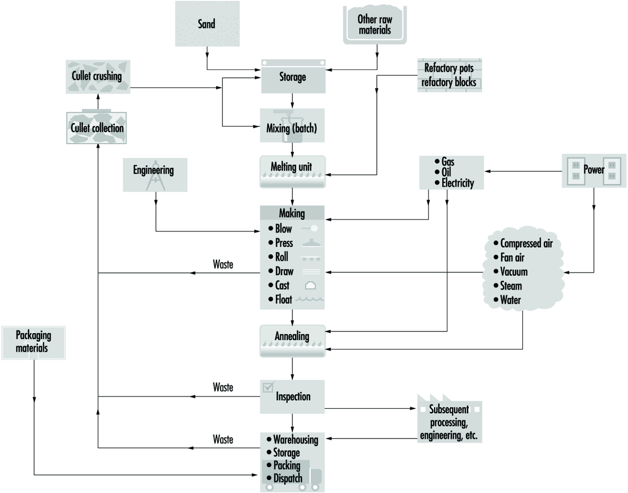
Figure 6 illustrates the basic principles of glass manufacture. The raw materials are weighed, mixed and, after the addition of broken glass (cullet), taken to the furnace for melting. Small pots of up to 2 tonnes capacity are still used for the melting of glass for hand-blown crystalware and special glasses required in small quantity. Several pots are heated together in a combustion chamber.
Figure 6. The processes & materials involved
In most modern manufacture, melting takes place in large regenerative, recuperative or electric furnaces built of refractory material and heated by oil, natural gas or electricity. Electric boosting and cold top electric melting were commercialized and became extensively utilized globally in the late 1960s and 1970s. The driving force behind cold top electric melting was emission control, while electric boosting was generally used in order to improve glass quality and to increase throughput.
The most significant economic factors concerning the use of electricity for glass furnace melting are related to fossil fuel costs, the availability of various fuels, electricity costs, capital costs for equipment and so on. However, in many instances the prime reason for the use of electric melting or boosting is environmental control. Various locations worldwide either already have or are expected soon to have environmental regulations that strictly restrict the discharge of various oxides or particulate matter in general. Thus, manufacturers in many locations face the possibility of either having to reduce glass melting throughputs, install baghouses or precipitators in order to handle waste flue gases or modify the melting process and include electric melting or boost. The alternatives to such modification may in some cases be plant shutdowns.
The hottest part of the furnace (superstructure) may be at 1,600 to 2,800°C. Controlled cooling reduces the glass temperature to 1,000 to 1,200°C at the point where the glass leaves the furnace. In addition, all types of glass are subjected to further controlled cooling (annealing) in a special oven or lehr. Subsequent processing will depend on the type of manufacturing process.
Automatic blowing is used on machines for bottle and lamp bulb production in addition to traditional hand-blown glass. Simple shapes, such as in insulators, glass bricks, lens blanks and so on, are pressed rather than blown. Some manufacturing processes use a combination of mechanical blowing and pressing. Wired and figured glass is rolled. Sheet glass is drawn from the furnace by a vertical process which gives it a fire-finished surface. Owing to the combined effects of drawing and gravity, some minor distortion is inevitable.
Plate glass passes through water-cooled rollers onto an annealing lehr. It is free from distortion. Surface damage can be removed by grinding and polishing after fabrication. This process has largely been replaced by the float glass process, which was introduced in recent years (see figure 7). The float process has made possible the manufacture of a glass that combines the advantages of both sheet and plate. Float glass has a fire-finished surface and is free from distortion.
Figure 7. Continuous float process
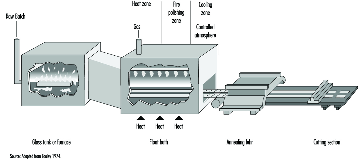
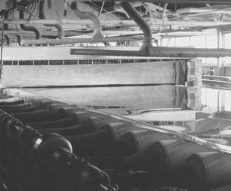
In the float process, a continuous ribbon of glass moves out of a melting furnace and floats along the surface of a bath of molten tin. The glass conforms to the perfect surface of the molten tin. On its passage over the tin, the temperature is reduced until the glass is sufficiently hard to be fed onto the rollers of the annealing lehr without marking its under surface. An inert atmosphere in the bath prevents oxidation of the tin. The glass, after annealing, requires no further treatment and can be further processed by automatic cutting and packing (see figure 8).
Figure 8. Ribbon of float glass exiting from lehr
The trend in new residential and commercial architecture toward the inclusion of more glazing area, and the need to reduce energy consumption, has put increased emphasis on improving the energy efficiency of windows. Thin films deposited at the surface of the glass provide low emissivity or solar control properties. The commercialization of such commodity-coated products requires a low cost, large area deposition technology. As a result, an increasing number of float glass manufacturing lines are equipped with sophisticated on-line coating processes.
In commonly used chemical vapour deposition (CVD) processes, a complex gas mixture is brought into contact with the hot substrate, where it pyrolytically reacts to form a coating at the surface of the glass. In general, the coating equipment consists of thermally controlled structures which are suspended over the width of the glass ribbon. They may be located in the tin bath, the lehr gap or the lehr. The function of the coaters is to uniformly deliver the precursor gases over the ribbon width in a temperature-controlled fashion and to safely extract the exhaust gas by-products from the deposition region. For multiple coating stacks, multiple coaters are used in series along the glass ribbon.
For the treatment of the exhaust gas by-products generated by such large-scale processes, wet scrubbing techniques with a conventional filter press are normally sufficient. When the effluent gases are not easily reacted or wetted by aqueous solutions, incineration is the primary option.
Some optical glasses are chemically strengthened by processes which involve immersing the glass for several hours in high-temperature baths containing molten salts of, typically, lithium nitrate and potassium nitrate.
Safety glass is of two major types:
- Toughened glass is made by pre-stressing by heating and then rapidly cooling pieces of flat glass of desired shape and size in special ovens.
- Laminated glass is formed by bonding a sheet of plastic (usually polyvinyl butyral) between two thin sheets of flat glass.
Synthetic Vitreous Fibres
General profile
Synthetic vitreous fibres are produced from a wide variety of materials. They are amorphous silicates manufactured from glass, rock, slag or other minerals. The fibres produced are both continuous and discontinuous fibres. In general, the continuous fibres are glass fibres drawn through nozzles and used to reinforce other materials, such as plastics, to produce composite materials with unique properties. The discontinuous fibres (generally known as wools) are used for many purposes, most commonly for thermal and acoustical insulation. Synthetic vitreous fibres, for purposes of this discussion, have been divided into continuous glass fibres, with the insulation wools made of glass, rock or slag fibres, and refractory ceramic fibres, which are generally aluminium silicates.
The possibility of drawing heat-softened glass into fine fibres was known to glass makers in antiquity and is actually older than the technique of glass blowing. Many early Egyptian vessels were made by winding coarse glass fibres onto a suitably shaped mandrel of clay, then heating the assembly until the glass fibres flowed into one another and, after cooling, removing the clay core. Even after the advent of glass blowing in the 1st century AD, the glass fibre technique was still employed. Venetian glassmakers in the 16th and 17th centuries used it for decorating glassware. In this case, bundles of opaque white fibres were wound onto the surface of a plain transparent blown glass vessel (e.g., a goblet) and then fused into it by heating.
Despite the long history of generally decorative or artistic uses of glass fibres, widespread use did not arise again until the 20th century. Initial commercial US production of glass fibres occurred in the 1930s, while in Europe the initial use occurred some years earlier. Rock and slag wools were produced several years earlier than that.
The manufacture and use of synthetic vitreous fibres is a global multi-billion-dollar industry since these useful materials have become an important component of modern society. Their uses as insulations have resulted in tremendous reduction in energy requirements for heating and cooling buildings, and this energy savings has resulted in significant reduction in global pollution associated with energy production. The number of applications of continuous glass filaments as reinforcements for a plethora of products, from sporting goods to computer chips to aerospace applications, has been estimated to be in excess of 30,000. The development and widespread commercialization of refractory ceramic fibres occurred in the 1970s, and these fibres continue to play an important role in protecting workers and equipment in a variety of high-temperature manufacturing processes.
Manufacturing processes
Continuous glass filaments
Glass filaments are formed by drawing the molten glass through precious-metal bushings into fine filaments of nearly uniform diameter. Due to the physical requirements for the fibres when used as reinforcements, their diameters are relatively large compared to those in the insulation wools. Almost all continuous glass filaments have diameters of 5 to 15 μm or greater. These large diameters, coupled with the narrow range of diameters produced during the manufacture, eliminate any potential chronic respiratory effects, as the fibres are too large to be inhaled into the lower respiratory tract.
Continuous glass fibres are made by the rapid attenuation of drops of molten glass exuding through nozzles under gravity and suspended from them. The dynamic balance between the forces of surface tension and mechanical attenuation results in the drop of glass taking on the shape of a meniscus held at the annular opening of the nozzle and tapering to the diameter of the fibre being drawn. For fibre drawing to be successful, the glass has to be within a narrow range of viscosities (i.e., between 500 and 1,000 poise). At lower viscosities, the glass is too fluid and falls away from the nozzles as drops; in this case surface tension dominates. At higher viscosities, the tension in the fibre during attenuation is too high. The rate of flow of glass through the nozzle can also become too low to maintain a meniscus.
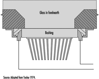
The function of the bushing is to provide a plate containing several hundred nozzles at a uniform temperature and to condition the glass to this uniform temperature so that the fibres drawn are of uniform diameter. Figure 9 shows a schematic diagram of the principal features of a direct-melt bushing attached to a forehearth from which it takes a supply of molten glass very near the temperature at which the glass will pass through the nozzles; in this case, therefore, the basic function of the bushing is also its sole function.
Figure 9. Schematic of direct-melt bushing
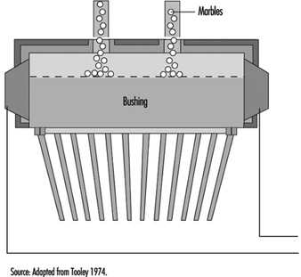
In the case of a bushing operating from marbles, a second function is required—namely, to first melt the marbles before conditioning the glass to the correct fibre-drawing temperature. A typical marble bushing is shown in figure 10. The broken line within the bushing is a perforated plate which retains the unmelted marbles.
Figure 10. Schematic of a marble bushing
The design of bushings is largely empirical. For reasons of resistance to attack by molten glass and stability at the temperatures needed for fibre drawing, bushings are made from platinum alloys; both 10% rhodium-platinum and 20% rhodium-platinum are used, the latter being more resistant to distortion at elevated temperatures.
Before the individual fibres being drawn from a bushing are gathered and consolidated into a strand, or a multiplicity of strands, they are coated with a fibre size. These fibre sizes are basically of two types:
- starch-oil sizes usually applied to fibres intended for weaving into fine fabrics or similar operations
- keying agent plus film-former sizes applied to fibres intended for the direct reinforcement of plastics and rubber.
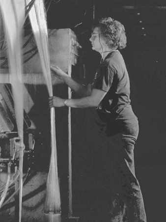
After the fibre is formed, a protective coating of organic sizing is applied at an applicator and the continuous filaments are gathered into a multifilament strand (see figure 11) before being wrapped on a winding tube. Applicators function by allowing the fan of fibres, when about 25 to 45 mm wide and on their way to the gathering shoe below the applicator, to pass over a moving surface covered with a film of fibre size.
Figure 11. Textile glass filaments
There are basically two types of applications:
- roller applicators, made of rubber, ceramic or graphite, in which the fibre runs over the surface of the roller coated with a film of fibre size
- belt applicators, in which at one end the belt passes over a driven roller which dips the belt into the fibre size and at the other end passes over a fixed hard chrome steel bar at which position the fibres touch the belt to pick up the size.
The protective coating and the fibre-gathering process can vary depending on the types of textile or reinforcement fibre being produced. The basic objective is to coat the fibres with size, gather them into a strand and locate them on a removable tube on the collet with the minimum necessary tension.
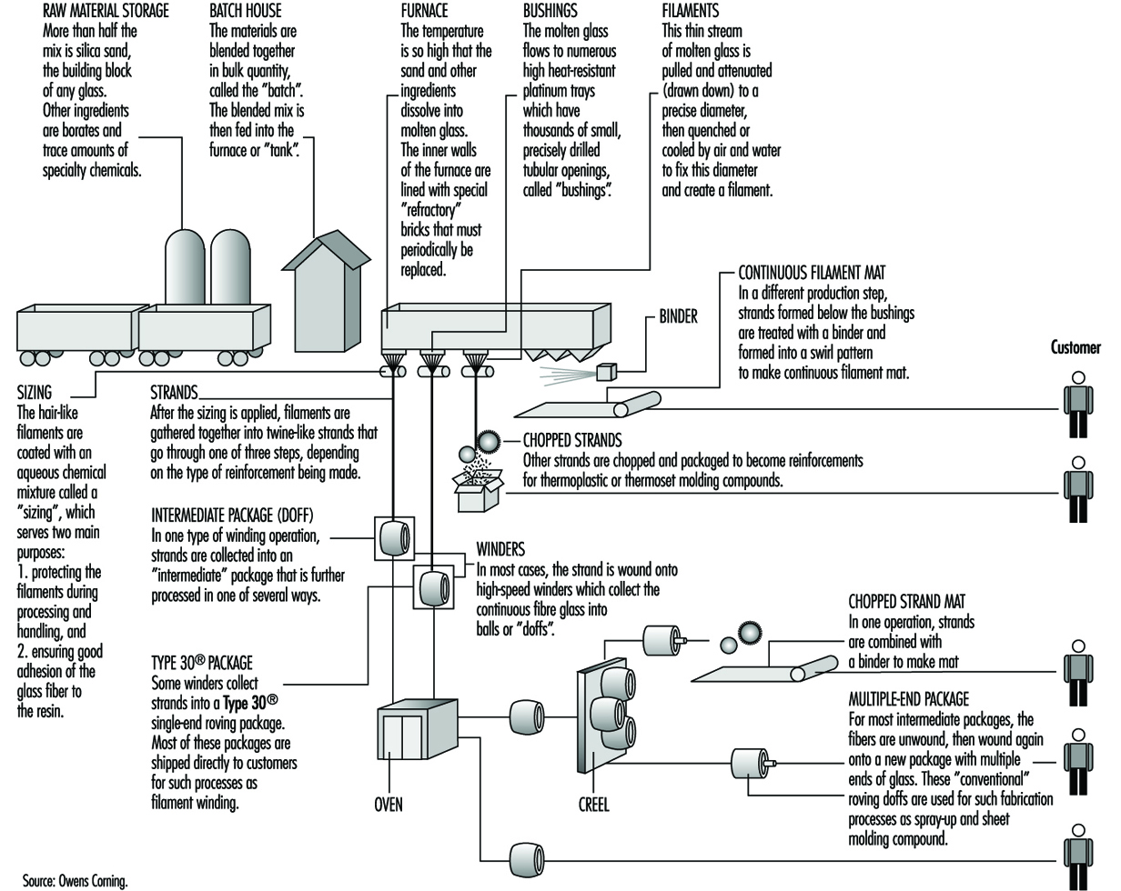
Figure 12 shows the process of continuous glass manufacturing.
Figure 12. Continuous filament glass manufacturing
Insulation wool manufacturing
In contrast to continuous filaments, the fibres of the insulation wools and refractory ceramic fibres are made in very high energy processes in which molten material is dropped into either spinning discs or a series of rotating wheels. These methods result in the production of fibres with a range of diameters much wider than seen with continuous filaments. Thus, all of the insulation wools and ceramic fibres contain a fraction of the fibres with diameters of less than 3.0 μm; these could become respirable if fractured into relatively short lengths (less than 200 to 250 μm). Extensive data are available on exposures to respirable synthetic vitreous fibres in the workplace.
Several processes are used to manufacture glass wool, including the steam blowing process and flame blown process; but the most popular is the rotary forming process developed in the mid-1950s. The rotary processes have largely replaced direct blowing processes for the commercial production of glass-fibre insulation products. These rotary processes all employ a hollow drum, or spinner, mounted with its axis vertical. The vertical wall of the spinner is perforated with several thousand holes uniformly distributed around the circumference. Molten glass is allowed to fall at a controlled rate into the centre of the spinner, from where some suitable distributor forces it to the inside of the vertical perforated wall. From that position, centrifugal force drives the glass radially outwards in the form of discrete glass filaments issuing from every perforation. Further attenuation of these primary filaments is achieved by a suitable blowing fluid emerging from a nozzle or nozzles arranged around and concentric with the spinner. The net result is the production of fibres with a mean fibre diameter of 6 to 7 mm. The blowing fluid acts in a downwards direction and so, as well as providing the final attenuation, it also deflects the fibres towards a collecting surface situated below the spinner. On the way to this collecting surface, the fibres are sprayed with a suitable binder before being uniformly distributed across the collecting surface (see figure 13).
Figure 13. The rotary process for making glass wool
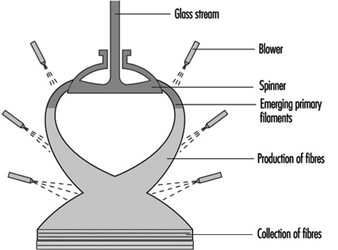
In a rotary process, glass wool fibres are made by allowing molten glass to run through a series of small openings which are situated in a revolving spinner and then attenuating the primary filament by air or steam blowing.
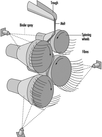
Mineral wool, however, cannot be produced on the rotary spinner process and historically has been produced in process with a series of horizontal spinning mandrels. The mineral wool process consists of a set of rotors (mandrels) mounted in a cascade formation and rotating very rapidly (see figure 14). A stream of molten stone is continuously transferred to one of the upper rotors and from this rotor distributed on the second and so on. The melt is uniformly spread on the outside surface of all the rotors. From the rotors, droplets are thrown out by centrifugal force. The droplets are attached to the rotor surface by elongated necks which, under further elongation and simultaneous cooling, develop into fibres. The elongation is, of course, followed by a decrease in diameter which, in turn, causes an accelerated cooling. Thus, there is a lower limit for the diameter among fibres produced in this process. A normal distribution of fibre diameters around the mean value is, therefore, not expected.
Figure 14. Mineral wool process (rock & slag)
Refractory ceramic fibres
Ceramic fibres are primarily produced by blowing and spinning with methods similar to those described for the insulation wools. In the steam blowing process, raw materials such as alumina and silica are fused in an electric furnace, and the molten material is drawn off and blown with either pressurized steam or other hot gas. The fibres produced are then collected on a screen.
Similar to the spinning process for rock and slag fibres, those for ceramic fibres produce a high proportion of long silky fibres. In this method, a stream of molten material is dropped onto rapidly spinning discs and thrown off tangentially to form fibres.
Pottery Industry
General profile
The making of pottery is one of the oldest of human crafts. Over the centuries different styles and techniques have developed in different parts of the world. In the 18th century, a flourishing industry in many parts of Europe was strongly influenced by the import of fine and highly decorated ware from the Far East. Japan had learned the ceramic art from China about 400 years earlier. With the Industrial Revolution and the general change in conditions in Western Europe, production grew rapidly. At present, almost every country manufactures some ware for domestic use, and pottery is an important export from some countries. Production is now on a factory scale in many parts of the world. While the basic principles of manufacture have not changed, there has been considerable progress in the way in which manufacturing is carried out. This is particularly so in the forming or shaping of ware, in its firing and in the decoration techniques used. The increasing use of microprocessors and robots results in the introduction of high levels of automation in production areas. However, there also still exist everywhere many small-scale craft potteries.
Methods of forming
The earliest method of making pottery involved the hand method of building. Coils of clay are wound around, one on top of the other, and stuck together by pressing with the hands. The clay is first made into a soft state by working it with water. The object is then shaped and moulded by hand, once the coils are adhered.
The potter’s wheel has become a tool for creating pottery. With this method of forming, a pile of clay is placed on a revolving circular plate and is shaped by the wet hands of the potter. The water keeps the potter’s hands from sticking to the clay and keeps the clay moist and workable. Handles, spouts and other protrusions from the spinning clay are placed on just before the object is fired.
Casting is often used today when pottery of a high quality is desired and when the walls of the vessel are to be very thin. A mixture of clay and water, called slip, is poured into a plaster-of-Paris mould. The plaster absorbs the water, causing a thin coat of clay to be deposited all around the inside of the mould. When the deposit of clay is thick enough to form the walls of the vase, the rest of the slip is poured out, leaving the wet piece of ware on the inside of the form. As this dries it shrinks somewhat and can be removed from the mould. Usually the moulds are so constructed that they can be taken apart.
When the piece becomes thoroughly dry, it is smoothed and prepared for the firing process. It is placed in a fire-clay box called a sagger, which protects the piece from the flames and gases that are emitted during the process, just as an oven would protect a loaf of bread that is being baked. The saggers are placed one on top of another in a kiln. The kiln is a large structure that is built of fire brick and is surrounded by flues so that the flames of the fire may totally surround the dishes yet never actually come in contact with them. Smoke would discolour the pieces if they were not protected in such a manner.
Most pieces are fired at least twice. The first time through the kiln is called the bisque firing, and the piece of pottery is called a biscuit or bisque piece. After firing, the biscuit ware is glazed. A glaze is a glassy, glossy coating that makes the pottery more attractive and serviceable. Glazes contain silica, a flux to lower the melting temperature (lead, barium and so on) and metal oxides as colourants. When the glaze is applied to the pottery and is completely dry, it is again placed back into the kiln and is fired at such a high temperature that the glaze melts and covers the entire surface of the pottery.
Kinds of pottery
- Stoneware is a pottery made from either light or dark clay. It is glazed on the unburned body either before setting in the kiln or by means of salt during the burning process and is burned to a dense, hard condition.
- Porcelain is a white, vitrified ware. It is translucent. In porcelain, the body and glaze are brought to completion and maturity at one and the same burning, which takes place at a very high temperature.
- China is a ware similar to porcelain. The body and glaze are brought to completion and maturity at the same firing, at extremely high temperatures.
- Bone china is a variety of china in which burned bone is used as an ingredient, constituting about 40% of the mass.
- Earthenware has a white or nearly white body. It is produced by two firings, like china, but its body remains porous. The glaze is similar to that of china but is made of a cheaper material.
- Faience is a fine glazed earthenware used for ornamental and decorative purposes. Usually there is no attempt to produce a white body, and the glazes are frequently coloured.
Manufacturing processes
The physical properties of pottery vary according to the composition of the body and conditions of firing. The body for any particular use is selected mainly for its physical properties, but white bodies are most usually chosen for tableware.
Industrial products (e.g., refractories, electrical insulators, catalyst carriers and so on) have a wide range of properties according to their eventual use.
Raw materials. The basic ingredients in a pottery body are shown in table 1, which also indicates typical proportions in sample body types.
Table 1. Typical body constituents (%)
|
Body |
Plastic Base |
Flux |
Filler |
|||||
|
Ball Clay |
Kaolin |
Stoneware clay |
Stone |
Feldspar |
Quartz |
Bone ash |
Other |
|
|
Earthenware |
25 |
25 |
15 |
35 |
||||
|
Stoneware |
30–40 |
25–35 |
20–25 |
20–30 (grog) |
||||
|
China |
20–25 |
20–25 |
15–25 |
25–30 |
||||
|
Porcelain |
40–50 |
20–30 |
15–25 |
|||||
|
Bone China |
20–25 |
25–30 |
45–50 |
|||||
Nepheline-syenite is sometimes used as flux, and alumina can replace some or all of the quartz filler in some porcelain-type bodies. Cristobalite (calcined sand) is used as a filler in some pottery bodies, particularly in the wall tile industry.
The body composition is determined partly by the required properties of the end product and partly by the production method. A plastic base is essential for ware that is shaped while moist, but not for non-plastic forming processes, such as dust pressing. The plastic base is not essential, although clay is still the principal ingredient in most ceramic products, including those prepared by dust pressing.
Industrial ceramics are not shown in table 1, as their composition ranges from all ball clay or fireclay, without additional flux or filler, to almost all alumina, with a minimal amount of clay and no added flux.
During firing, the flux melts to a glass to bind the ingredients together. As the amount of flux increases, the temperature of vitrification is lowered. Fillers influence the mechanical strength of the clayware before and during firing; in making tableware, quartz (as sand or calcined flint) is traditionally used, except that bone ash is used in making bone china. The use of alumina or other non-siliceous fillers, which are already employed in the manufacture of industrial ceramics, is being extended to the making of other ware, including domestic products.
Processing. The basic processes in the production of pottery include:
- preparation of the body ingredients
- forming and shaping
- biscuit firing
- application of glaze
- glost firing
- decoration.
The preparatory processes of calcining, crushing and grinding of flint or stone may be done in a separate establishment, but it is usual for all subsequent processes to be carried on in the same factory. In the slip house, the body ingredients are blended in water; plastic clay is then produced by filtering and plugging; the casting slip is then prepared by blunging to a creamy consistency. Dust for pressing is prepared by drying and grinding.
Traditional classifications of shaping processes are shown in table 2. In casting, a water suspension of the body is poured into an absorbent mould and the cast is removed after partial drying. Plastic clay shaping by throwing is now rare in industrial production; mechanical spreading over or in a plaster mould (jiggering and jolly) with separation from the mould after drying is almost universal in making tableware. Pressing of plastic clay or extrusion is mainly restricted to industrial ceramics. Dust-pressed articles are produced by compacting pre-dried body-dust by hand or mechanical pressing.
Table 2. Manufacturing processes
|
Products |
Usual processes |
|
Tables |
Plastic clay shaping; casting |
|
Sanitary ware |
Casting |
|
Tiles |
Dust pressing (wall or vitrified floor tiles), plastic clay pressing (floor quarries) |
|
Industrial ware |
Dust pressing, plastic clay pressing |
After shaping, the ware may be dried and finished by fettling, towing or sponging. Then it is ready for biscuit firing.
After biscuit firing, glaze is applied by dipping or spraying; dipping may be by hand or mechanized. The glazed ware is then fired again. Sometimes, as with sanitary whiteware, glaze is applied to the dried clay article and there is only one firing.
Decoration may be applied either under or over glaze and may be by hand painting, machine printing or transfer; over-glaze decoration involves a third firing; and sometimes separate firings for different colours are necessary.
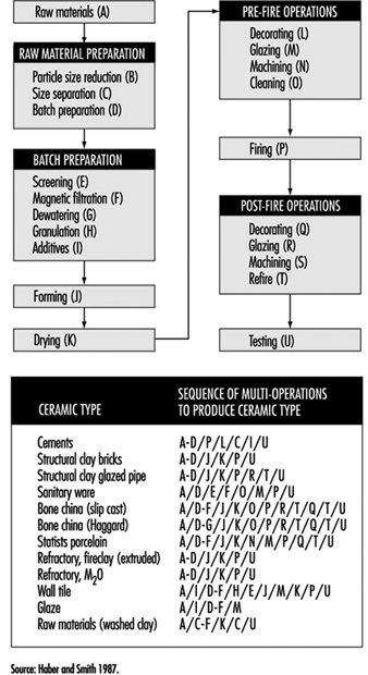
In the final stages, the ware is sorted and packed for shipping. Figure 15 identifies the various paths followed by various types of pottery and ceramics during their fabrication.
Figure 15. Flow chart by type of ceramic
Ceramic Tile
General profile
Ceramic is a term once thought to refer only to the art or technique of producing articles of pottery. The etymology of the term shows that it derives from the Greek keramos, meaning “a potter” or “a pottery”. However, the Greek word is related to an older Sanskrit root, meaning “to burn”; as used by the Greeks themselves, its primary meaning was simply “burnt stuff” or “burnt earth”. The fundamental concept contained in the term was that of a product obtained through the action of fire upon earthy materials.
A traditional ceramic, in the context of this article, refers to the products commonly used as building materials or within the home and industry. Although there is a tendency to equate traditional ceramics with low technology, advanced manufacturing technologies are often used in this industry. Stiff competition among producers has caused the technology to become more efficient and cost effective by utilizing complex tooling and machinery, coupled with computer-assisted process control.
The oldest ceramic products originated from clay-bearing materials. Early potters found the plastic nature of clay to be useful in forming shapes. Because of its tendency to exhibit a large amount of shrinkage, clay bodies were modified by adding coarse sand and stone, which reduced shrinkage and cracking. In modern clay-based bodies, the typical non-clay additions are silica flour and alkali minerals that are added as fluxes. In traditional ceramic formulations, clay acts as a plasticizer and binder for other constituents.
Development of the industry
The production of dried and fired clay tiles has very ancient origins dating back to Middle Eastern populations. The tile whiteware industry developed significantly in Europe, and by the beginning of the 20th century floor and wall tile production achieved industrial scale. Further development in this field occurred after the Second World War. Europe (Italy and Spain, in particular), Latin America and the Far East are now the most important areas of industrial tile production.
The floor and wall tile sector of the whiteware industry has seen a great deal of development since the mid-1980s with the introduction of new technologies, automation and integration of production flow into the manufacturing process. Subsequently, productivity and efficiency increased, while energy consumption and costs have been reduced. Tile manufacturing is now continuous in both wet and dry tile production, and many plants today have nearly 100% automation. The major innovations in the tile industry during the last decade include wet grinding, spray drying, high-pressure dry pressing, roller drying and fast-firing technologies.
The value of the US ceramic tile market supply (US factory shipments plus imports) increased an estimated 9.2% compounded annually between 1992 and 1994. Dollar sales were estimated to have reached US$1.3 billion in 1994. At the same time, volume sales rose 11.9% compounded annually to 1.3 billion square feet. This compares with a market growth rate of 7.6% based on dollar sales, and 6.9% based on volume sales between 1982 and 1992.
Classifications of ceramic tiles
Redware and whiteware
Many types of ceramic tile are available on the market. They differ according to the condition of the surface, colour of the body (white or red), manufacturing technology, raw materials and end use. The difference between “red” and “white” tiles lies in the amount of iron minerals contained in the body. By reacting with the other body components, they can give more or less colouration and modify the behaviour of the body during firing.
A complete and exhaustive classification is very difficult owing to the extreme heterogeneity of the tile products, their processing and subsequent characteristics. In this chapter, European (EN) and ASTM standards are considered.
EN standards exclusively classify ceramic tiles as a function of water absorption (which directly correlates to the porosity) and shaping method (extrusion or pressing). The shaping methods are classified as:
- shaping process A (extruded floor tiles). This process includes split tiles and individually extruded tiles.
- shaping process B (dry-pressed floor and wall tiles).
European Standard EN 87, approved in November 1981, specifies that “Ceramic wall and floor tiles are building materials that are generally designed for use as floor and wall coverings, both indoors and outdoors, regardless of shape and sizes”.
The American National Standards Institute (ANSI) specification for ceramics tile (ANSI A 137.1) contains the following definitions:
- Ceramic mosaic tile is formed by either the dust-pressed or plastic method, usually 6.4 to 9.5 mm (1/4 to 1/8 in.) thick, and has a facial area of less than 39 cm2 (6 in2 ). Ceramic mosaic tiles may be either porcelain or natural clay composition, and they may be either plain or with an abrasive mixture throughout.
- Decorative wall tile is glazed tile with a thin body that is usually non-vitreous and suitable for interior decorative residential wall use where breaking strength is not a requirement.
- Paver tile is glazed or unglazed porcelain or natural clay tile formed by the dust-pressed method having 39 cm2 (6 in2 ) or more facial area.
- Porcelain tile is ceramic mosaic tile or paver tile that is generally made by the dust-pressed method with the resulting tile composition that is dense, impervious, fine-grained and smooth, with a sharply formed face.
- Quarry tile is glazed or unglazed tile, made by the extrusion process from natural clay or shale, usually having 39 cm2 (6 in2) or more facial area.
- Wall tile is glazed tile with a body that is suitable for interior use and usually non-vitreous and is not required to withstand excessive impact or be subject to freezing and thawing conditions.
- Individual tile whiteware grades include unglazed tiles (ceramic mosaic tile, quarry tile, paver tile) and glazed tiles (glazed wall tile, glazed ceramic mosaic tile, glazed quarry tile, glazed paver tile) (ANSI 1988).
The tiles are manufactured by standard ceramic processes. Ceramic wall and floor tiles are prepared from a mixture of ball clays, sand, fluxes, colouring agents and other mineral raw materials, and they undergo processing such as milling, screening, blending and wetting. They are shaped by a pressing, extrusion, casting or other process, normally at room temperature, and are subsequently dried and finally fired at high temperature. Tiles may be glazed, unglazed or engobed. Glazes are glasslike, impervious coatings, and engobes are matte, clay-based coatings that may also be porous. Glazed wall and floor tiles are produced either by single-or two-stage firing.
Traditional ceramic bodies are formed into shapes using many different techniques. The specific forming process is dictated by numerous factors, including material characteristics, size and shape of the part, part specifications, production yield and accepted practices within the geographic region.
Clay-based bodies are heterogeneous mixtures of one or more clays and one or more nonclay powders. Before attaining a final shape, these powders undergo a sequence of unit operations, firing and post-fire operations (see figure 17).
For most traditional bodies, forming techniques can be classified as soft plastic forming, stiff plastic forming, pressing and casting.
Applied pressure is employed to rearrange and redistribute the raw materials into a better-packed configuration. The rheological behaviour of clay-based bodies results from clay mineral inter-action with water, which imparts plasticity to the batch. In nonclay bodies, this same type of behaviour can be achieved by adding plasticizers.
Industrial Ceramics
General profile
Ceramics differ from other engineering materials (metals, plastics, wood products, textiles) in a number of individual properties. Perhaps the most distinctive difference to a designer or potential user of ceramic ware is the unique shape and size of each individual ceramic piece. Ceramics are not readily shaped or worked after firing, except by very costly grinding; consequently, they normally must be used as is. Except for some simple tile, rod and tube shapes of limited sizes, ceramics cannot be marketed by the foot or by the yard, nor cut to fit on the job.
All the useful properties, including shape and size, must be provided in advance, beginning with the very early stages of ceramic processing. The structural integrity of each piece must be preserved through a variety of thermal and mechanical stress exposures during processing and until the piece is finally installed and in service. If a ceramic should fail in service as a result of a variety of causes (brittle fracture on impact, thermal shock, dielectric breakdown, abrasion or melting slag corrosion), it is not likely to be repairable, and usually must be replaced.
Significant advances have been made in fundamental understanding and technological control of the properties of ceramics, and of their utilization in many new, demanding, highly technical applications. The industry in general, and the technical and electronic ceramic portions of it in particular, have devised production and control techniques for mass producing complex shapes in bodies having carefully controlled electrical, magnetic and/or mechanical properties while maintaining dimensional tolerances that are good enough to permit relatively easy assembly with other components.
Many ceramics are produced in large volume as standard items. Refractory bricks and shapes, crucibles, muffles, furnace tubes, insulators, thermocouple protection tubes, capacitor dielectrics, hermetic seals and fibre boards are routinely stocked by a number of ceramic producers in a variety of compositions and sizes. It is usually quicker and cheaper to use stock items whenever possible. When stock items will not meet the need, most manufacturers are prepared to custom produce items. The more stringent the requirements for a given property of the ceramic, or the more restrictive the requirements for specific combinations of properties, sizes and shapes, the more limited are the accepted compositional, microstructural and configurational parameters for the ceramic. Hence the cost and difficulty of manufacture are greater. Most ceramic manufacturers have experienced staff engineers and designers who are well qualified to work with potential customers on details of ceramic ware design.
Markets
The major market for state-of-the-art ceramics has been and will continue to be in electronics, but vigorous worldwide research and development programmes are continuously searching for new applications and identifying ways of improving ceramic properties such that new markets can be accessed.
Advanced ceramics are produced in Japan, the United States and Western Europe. The raw materials used in the industry are traded on an international basis, principally as powders, but there is also a significant amount of in-house processing.
The major applications of industrial ceramics are:
- Oxides. The main oxide materials in use today are alumina in spark plugs, substrates and wear applications; zirconia (ZrO2) in oxygen sensors, as a component in lead-zirconium-titanate (PZT) piezoelectrics, wear applications and thermal barrier coatings; titanates in barium titanate capacitors and PZT piezoelectrics; and ferrites in permanent magnets, magnetic recording heads, memory devices, temperature sensors and electric motor parts.
- Carbides and nitrides. Carbides (mainly silicon carbide and boron carbide) are used in wear applications, while nitrides (mainly silicon nitride and Sialon) are used in wear applications and cutting tools. Aluminium nitride, with its high thermal conductivity, is the primary contending material for part of the electronics substrate market currently dominated by alumina.
- Mixed oxide ceramics. Ceramics research and development efforts are focused on a number of new applications for ceramics that all have enormous potential. Three significant applications are: (1) ceramic superconductors, (2) ceramics for solid oxide fuel cells and (3) ceramic components for heat engines.
Ceramic superconductors are based on a number of mixed oxide systems that include yttrium, barium, copper, strontium and copper (YBa2Cu3O7-8, Bi2Sr2CaCu2O8, Bi2Sr2Ca2Cu3O10) stabilized with lead oxide. Solid oxide fuel-cell ceramics are based on ionic conductors in which high-purity stabilized zirconia is currently the material of choice. Ceramic heat-engine components under investigation are composed of silicon carbide, Sialons and zirconia, either as single-phase ceramics, ceramic-ceramic composites or metal-matrix composites (MMCs).
Manufacturing processes
Manufacturing technology development
Processing innovations. Research and development activity is generating new technologies for the production of ceramic materials. Precursor-derived ceramics were estimated to have a market value of US$2 million in 1989, the major part of which was in CVD (86% of the total market value). Other segments of this growing market include chemical vapour infiltration (CVI), sol-gel and polymer pyrolysis. Products that are being successfully produced by these means include continuous ceramic fibres, composites, membranes and ultra-high-purity/high-activity powders.
The processes used to convert these raw materials to finished products include additional powder processing (e.g., milling and spray drying) prior to forming green shapes that are then fired under controlled conditions. The forming processes include die pressing, isostatic pressing, slip casting, tape casting, extrusion, injection moulding, hot pressing, hot isostatic pressing (HIP), CVD and so on.
Chemical additives to aid ceramic processing. Each step in the manufacturing process requires careful control so that end-product properties are obtained at maximum production efficiency and key effect chemicals are used to optimize powder treatment and green forming. The effect chemicals include milling aids, flocculants and binders, lubricants to effect product release during pressing and minimize wear of die parts, and plasticizers to aid extrusion and injection moulding. A list of such chemicals is shown in table 3. While these materials play an important economic role in production, they are burnt out during firing and play no part in the final product chemistry. The burn out process has to be carefully controlled to avoid residual carbon in the finished products, and process research and development is continuously investigating ways of minimizing the levels of effect chemicals used.
Table 3. Selected chemical additives used to optimize powder treatment and green forming of ceramics
|
Material |
Application or function |
|
Polyvinyl alcohol |
Binder for advanced ceramics |
|
Polyethylene glycol |
Binder for advanced ceramics |
|
Sodium polyacrylate |
Deflocculant for slip casting |
|
Tertiary amide polymer |
Binder for dry pressing |
|
Starch blended with dry colloidal aluminosilicate |
Binder for vacuum forming |
|
Cationic alumina plus organic flocculant |
Binder for vacuum forming |
|
Pre-gelled, cationic corn starch |
Flocculant for colloidal silica and alumina binder |
|
High-purity sodium carboxymethylcellulose |
Binder |
|
Inorganic colloidal magnesium aluminium silicate |
Suspending agent |
|
Medium-viscosity sodium carboxymethylcellulose added to Veegum |
Suspending agent, viscosity stabilizer |
|
Ammonium polyelectrolyte |
Dispersing agent for casting slips for electronic ceramics |
|
Sodium polyelectrolyte |
Dispersing agent binder for spray-dried bodies |
|
Microcrystalline cellulose and sodium carboxymethylcellulose |
Thickening agent |
|
Polysilazane |
Processing aid, binder and precursor for advanced ceramics |
In addition to spawning ceramic products and ceramic manufacturing technologies for new applications, the influence of the advanced ceramics industry on the traditional ceramics industry should not be overlooked. It is expected that many high-technology materials and processes will find application in the traditional ceramics industry as the latter strives to reduce manufacturing costs, to improve quality and to give better value in service to the end user.
Raw materials
There are certain key materials that are either used directly by the ceramics industry or that represent the starting point for the production of added-value materials:
- silica
- clay
- alumina
- magnesia
- titania
- iron oxide
- zircon/zirconia.
This discussion will focus on the properties of silica, alumina and zircon/zirconia.
Silica, in addition to its use in refractories and whitewares, is also the starting point in the manufacture of elemental silicon, silicon carbide and silicon tetrachloride. Silicon, in turn, is the starting point for silicon nitride, and silicon tetrachloride is the precursor for a wide range of silicon organics that can be pyrolyzed under controlled conditions to high-quality silicon carbide and silicon nitride.
Silicon nitride and its Sialon derivatives, as well as silicon carbide, despite their tendency to oxidize, have the potential to meet many of the property targets set by the heat-engine market. A feature of silica and the ceramic materials that are derived from silica is that all the elements are readily available in the earth’s crust. In this respect, these materials offer the potential of ease of supply in all parts of the world. In practice, however, there is a significant energy input required to produce silicon and silicon carbide. Consequently, manufacture of these materials is by and large limited to countries with cheap and readily available electric power.
Alumina is found throughout the earth’s crust as a component in aluminosilicate minerals. Economics dictate that alumina be extracted from bauxite using the Bayer process. Bauxite is widespread in the equatorial belt in different states of purity, and is divided into two classifications: refractory grade ore and metallurgical ore.
Refractory grade bauxite is supplied by China and Guyana as a high-temperature calcine of the naturally occurring mineral: diaspore (Al2O3·H2O) in China and gibbsite (Al2O3·3H2O) in Guyana. During calcination, a complex phase assemblence of corundum (Al2O3), mullite, silica glass and minor levels of aluminium titanate is formed. The consumption of refractory grade bauxite exceeds 700,000 tonnes per year on a worldwide basis.
Metallurgical grade bauxite is mined in Australia, Jamaica and West Africa, and has variable alumina levels in conjunction with major impurities such as iron oxide and silica. The alumina in the metallurgical ores is extracted from the ore when dissolved by sodium hydroxide, yielding a sodium aluminate solution that is separated from the iron oxide and silica, which are rejected as a waste product in the form of red mud. Essentially, pure aluminium hydroxide is precipitated from the sodium aluminate and then calcined to a number of grades of alumina.
The high-purity aluminas used in the ceramics industry and derived by the Bayer process are classified as tabular alumina, fused alumina or speciality calcined alumina.
Tabular alumina is produced by high-temperature (~2,000°C or 3,630°F) calcination of low-temperature calcined alumina in large, oil-fired rotary kilns. Fused alumina is produced by the electric melting of calcined alumina. Tabular and fused alumina are sold to the refractory industry in crushed and graded form for use in a wide range of high-quality products, such as in continuous casting refractories (e.g., single-edge-notched or SEN/slide gates), monolithic refractories for application in blast furnaces and the petrochemical industry.
Speciality calcined alumina powders are the major raw materials used in the advanced ceramics industry for both electronic and engineering applications. The powders are produced in a wide range of grades according to exacting specifications of chemistry, particle size and crystal type, to suit a wide range of end-product applications.
There is an established international trade in high-quality aluminas. Many of the ceramic manufacturers have in-house milling and spray drying facilities. There is clearly a limitation to the growth in the supply of spray-dried systems and a continuing need to supply aluminas which match the customer plants so that use of the latter can be optimized at an acceptable price. Alumina is a significant ceramic material that is available at a high degree of purity. The dominant position of alumina as a ceramic raw material arises because it has desirable properties at a relatively low cost. This cost effectiveness is attributable to the commodity nature of the business arising from the large demand for alumina by the aluminium industry.
Zircon and zirconia. The primary source of zirconia is the mineral zircon (ZrO2 SiO2), which exists in beach sands principally in Australia, South Africa and the United States. Zircon extracted from beach sands contains about 2% hafnium oxide and traces of Al2O3 (0.5%), Fe2O3 (0.1%) and TiO2 (0.1%). In addition, all zircons contain traces of uranium and thorium. Zircon is processed by fine grinding to produce a range of milled products of defined particle size. These products have found use in investment casting, foundries, refractory products and as an opacifier in glazes for whitewares.
Zircon is also the principal source of zirconia. Zircon can be chlorinated in the presence of carbon to give zirconium and silicon tetrachlorides that are then separated by distillation. The zirconium tetrachloride produced can be used to prepare zirconia directly or as a feedstock for other zirconium chemicals. Sintering with alkali or alkaline earth oxides is also used to decompose zircon. Silica is leached from the decomposition products with water, leaving zirconium hydroxide to be further purified by acid dissolution and reprecipitation. Zirconia is then obtained by calcining the hydroxide. Zircon is also converted to zirconia and silica in a plasma at 1,800°C (3,270°F) with rapid cooling to prevent reassociation. The free silica is removed by dissolution in sodium hydroxide. Fused zirconia is produced in electric arc furnaces from either baddeleyite or zircon/carbon feedstocks. In the latter process the silica component of zircon is carbothermally reduced to silicon monoxide, which volatilizes prior to the fusion of the residual zirconia.
Summary
The industrial ceramic industry is very diverse and there is much in-house processing. Many of the final manufacturing operations are in foundry-type atmospheres. The material-handling systems in these operations convey fine raw materials where dust can be an issue. Materials are then raised to very high temperatures and melted or fused into shapes needed for the final parts. Therefore, many of the safety issues which exist in any high-temperature industry also exist in the industrial ceramics industry.
Brick and Tile
General profile
Bricks and tiles made from clay have been used as building material since the earliest times in many parts of the world. When properly made and fired they are more durable than some stones, resistant to weather and great changes of temperature and moisture. The brick is a rectangle of standard size, varying slightly from region to region but essentially convenient for handling with one hand by a bricklayer; roofing tiles are thin slabs, either flat or curved; clay tiles may also be used for floors.
The brick industry is very fragmented. There are many small suppliers located all over the world. Brick manufacturing tends to involve local suppliers and local markets due to the cost of shipping of the finished product. In 1994, there were 218 brick manufacturing plants in the United States, and in 1992 the number of producers of structural clay products in the UK was listed at 182, for example. Brick manufacturers generally are located near the clay deposits to reduce raw material shipping cost.
In the United States, bricks are used primarily in residential construction as either a load-bearing material or as a facade material. Since the brick industry is so closely coupled to the housing industry, manufacturing activity is highly dependent on the residential construction industry and almost totally dependent on the combined residential and non-residential construction industry.
Manufacturing processes
Materials and processing
The basic material is clay of various kinds with mixtures of loams, shales and sand, according to local supply and needs, to give the required properties of texture, plasticity, regularity and shrinkage, and colour.
Extraction of clay is now often fully mechanized; manufacture usually takes place alongside the extraction hole, but in large works the clay is sometimes conveyed in skids on ropeways. The subsequent processing of the clay varies according to its constitution and the end-product, but in general includes crushing, grinding, screening and mixing. See figure 16 for a typical brick-manufacturing operation.
Figure 16. The manufacture of bricks & tiles
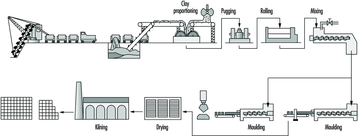
Clay for wire-cut bricks is broken up by rollers; water is added in a mixer; the mixture is rolled again and then fed through a horizontal pugmill. The plastic clay extruded is then cut to size on a wire-cutting table. Semi-dry and stiff plastic material is produced by rolling and screening and is then fed to mechanical presses. Some bricks are still hand moulded.
Where plastic material is used, the bricks have to be dried either by sun and air, or more frequently in regulated kilns, before firing; bricks made from semi-dry or stiff plastic may be fired immediately. Firing may take place in ring kilns, often hand fed, or in tunnel kilns, mechanically fed. The fuels used will vary according to local availability. A finishing glaze is applied to some decorative bricks.
Refractories
General profile
Refractory materials are traditionally thought of as non-metallics that resist degradation by corrosive gases, liquids or solids at elevated temperatures. These materials must withstand thermal shock caused by rapid heating or cooling, failure attributable to thermal stresses, mechanical fatigue due to other material contacting the refractory itself and chemical attack activated by the high-temperature environment. These materials are required for the manufacture of most ceramic products and are specifically needed in ovens, dryers, furnaces and high-temperature-bearing engine parts.
Refractories remained almost exclusively mineral-based until well into the 20th century. Yet technologists who were skilled in mineralogy were paying attention. Metallurgists had been experimenting with acid and basic slagging practices since the Middle Ages and had catalogued some of the benefits of each. Refractory artisans had correspondingly experimented with ganister, with other nearly pure silica minerals and with magnesite, a predominantly MgCO3 mineral which was calcined to MgO. When the Bessemer steel-making converter was invented in 1856, combining working temperatures of over 1,600ºC with corrosive acid slagging, “acid” silica refractories were all but ready. When the Siemens open hearth furnace followed in 1857 at even higher temperatures, and steel making went over in both cases to corrosive basic slagging, “basic” magnesite linings were soon introduced. Basic refractories made from dolomite (MgO-CaO) were developed during the First World War, when the European magnesite supply was cut off from the Allies. Later, with the development of other mineral resources worldwide, magnesite reasserted itself.
Table 4. Refractory usage by industry in the United States
|
Industry |
Percentage of total US sales |
|
Iron and steel |
51.6 |
|
Nonferrous metals |
7.5 |
|
Cement |
4.9 |
|
Glass |
5.1 |
|
Ceramics |
9.7 |
|
Chemical and petroleum |
2.1 |
|
Public utilities |
0.9 |
|
Export |
7.4 |
|
All other and unspecified |
10.8 |
Meanwhile, bonded carbon bricks were produced in the United Kingdom starting in 1863 and eventually found their way into the iron-smelting blast furnace as its working temperatures climbed still higher. They also went quickly into the Hall-Héroult cells for the production of aluminium (1886).
Lime had been made for some 5,000 years using clay and then firebrick kilns. Portland cement manufacturing first called for an innovative refractory when rotary kilns were introduced after 1877. The first resistant linings were made of cement-bonded cement clinker. Later on more durable commercial refractories returned to this industry.
Recuperative and regenerative furnaces, originating in the newborn manufacture of steel in the 1850s, were introduced into nonferrous metallurgy and glassmaking in the late 19th century. Fireclay refractories had to be superseded there, too. Magnesite linings were used in copper converters from 1909, and in the first modern glass tanks about 10 years later. Electric arc furnaces were first tried for steel making in 1853 and became common after 1990. A roughly 100-tonne unit installed in the United States in 1927 employed a magnesite lining.
Three-phase arc furnaces were in place before 1950; it was only then that serious demands arose for more sophisticated refractories. In the same time frame, oxygen blowing was introduced into Bessemer and open-hearth furnaces in the 1940s. The basic oxygen furnace (BOF) literally took over steel making in the late 1950s. Oxygen blowing, by its sheer economic importance, impelled the refractories industry for the first time to introduce synthetic materials into its products on a significant scale.
Properties of refractory materials
The properties that characterize quality refractory materials depend on the nature of the application. The most important aspect of the materials is referred to as “refractoriness”. This term refers to the point at which the specimen begins to soften (or melt). Typically, refractories do not have a specific melting point; the phase transition proceeds over a range of temperatures in a phenomenon called softening. This characteristic is often quantified with a pyrometic cone equivalent (PCE), which is a measure of heat content measured by the slumping of a cone during thermal cycling.
A related, and often more useful property, is the temperature of failure under load. Refractories often fail under load at temperatures much less than the temperature that corresponds to the PCE. In obtaining a value for this parameter, the refractory is subjected to a known load and is subsequently heated. The temperature at which sagging or general deformation occurs is reported. This is of great interest because the value is used to predict mechanical properties during use of the refractory. The load-bearing ability of refractory materials is directly proportional to the amount of viscosity of the glass present.Another factor that is essential to understanding the performance of a refractory is the dimensional stability. Throughout industrial use, refractory materials are subjected to heating/cooling cycles, which cause the refractory units to either expand or contract. Large changes in the dimensions will reduce stability and may ultimately lead to failure of the refractory-based structure.
A related phenomenon commonly observed with refractory materials is spalling. Spalling is generally considered fracture, splitting or flaking of the refractory, resulting in the exposure of the inner mass of the material. Spalling is usually brought about by temperature gradients within the material, compression in the structure due to large-volume charges and variations of the thermal expansion coefficient within the brick. Every effort is made in refractory manufacture to avoid spalling because it reduces the effectiveness of the refractory.
Refractories have application across a wide variety of industrial applications ranging from extensive use in the iron and steel industry to low volume usages in the cement and public utilities industries. Basically, refractories are used in any industry where high temperatures are used to heat and dry or incinerate material. Table 4 provides a current breakdown by industry of refractory usage within the United States.
As shown in table 4 the steel industry is the area where over 50% of the refractory produced in the U.S. is utilized. Therefore, the needs of the steel industry to a great extent have driven the refractory developments which have occurred.
Modern refractories
Ceramics had grown substantially from craft to applied science. The American Ceramic Society had been founded in 1899, the British Ceramic Society in 1901. Oxide phase diagrams began to appear in the literature in the 1920s. The techniques of petrography were well developed, and the detailed mechanisms of refractory degradation and wear were beginning to be understood. American refractory producers had become largely reorganized, consolidated and capable of performing their own research. The tools of refractory synthesis and instruments of investigation were both burgeoning.
Synthetic industrial carbons were, of course, not new. Coke was first made commercially from coal in the 1860s, and from petroleum shortly thereafter. Synthetic graphite and silicon carbide appeared almost simultaneously at the turn of the century, following Acheson’s invention of the self-resistance-heated electric furnace in 1896. These products, having properties quite unlike those of oxides, rapidly stimulated their own uses and markets.
Synthetic alumina, Al2O3, had been available since the Bayer process started feeding aluminium production about 1888. Synthetic magnesia (MgO) was first made from seawater in the United Kingdom in 1937 and in the United States in 1942, stimulated by wartime needs for magnesium. Zirconia had become available, also spurred by the military. Lime had been a major commodity for ages. A host of other chemicals were on hand for consideration as refractory components or as minor additives and bonding agents. The only important component of oxide refractories that for the most part has resisted replacement by synthetics is silica (SiO2) High-purity silica rocks and sands abound and are used in this industry as well as in glass formulation.
The use of synthetics in refractory manufacture has been enormously helpful; but mineral raw materials have by no means been displaced. Synthetics cost more, and that cost has to be justified. Some synthetic materials create severe problems in refractory processing, and new ways must be found to overcome these. Optimum results have often been achieved by combinations of synthetic and mineral raw materials, along with creative inputs into their processing.
Mixtures of clay with carbon had been used to line crucibles and ladles since iron was first poured; and silica bricks containing carbon were made in France in the 1860s. Since 1960 both the techniques and the compositions have changed dramatically. The use of carbon-bearing oxide refractories has mushroomed, starting with MgO+C. The first real impetus may have been provided by the BOF; but today there is hardly any advanced oxide refractory type that cannot be had either with or without added carbon or a carbon precursor for superior performance in specific applications.
Arc-fused refractory grain or aggregate had been made since the early 1900s, and fused-cast refractory bricks of several compositions followed in the twenties and thirties, notably of mullite, alumina, magnesia-alumina-silica and alumina-zirconia-silica. More often than not, these products were made entirely from mineral raw materials.
In fact, all-mineral-based refractories remain today an important component of the product menu. They are on the whole cheaper, they often perform admirably and there are still many applications of lesser demand as well as those of critical demand for the highest levels of refractoriness and corrosion resistance.
Refractory industry
Refractories will be found in use in many industries for lining boilers, kilns and furnaces of all kinds, but the largest percentage are used in manufacture of metals. In the steel industry, a typical blast or open-hearth furnace may use many different types of refractories, some made from silica, some from chrome and/or magnesite and others of fire clay.
Much smaller quantities are also used in the following industries: gas, coke and by-products; power-generating plants; chemicals; bake ovens and stoves; cement and lime; ceramics; glass; enamels and glazes; locomotives and ships; nuclear reactors; oil refineries; refuse disposal (incinerators).
Manufacturing processes
The type of refractory that is used in any particular application depends on the critical requirements of the process. For example, processes that demand resistance to gaseous or liquid corrosion require low porosity, high physical strength and abrasion resistance. Conditions that demand low thermal conductivity may require entirely different refractories. Indeed, combinations of several refractories are generally employed. There is no well-established line of demarcation between those materials that are and those that are not refractory, although the ability to withstand temperatures above 1,100°C without softening has been cited as a practical requirement of industrial refractory materials.
The technical goals of manufacture of a given refractory are embodied in its properties and performance in an intended application. The tools of manufacture consist of choices among raw materials and among processing methods and parameters. The requirements of manufacture have to do with the features of phase composition and microstructure—collectively called material character—that are developed through processing and are themselves responsible for product properties and behaviour.
Raw materials
In the past, refractory raw materials were selected from a variety of available deposits and used as mined minerals. Selective mining yielded materials of the desired properties, and only in cases of expensive raw materials, such as magnesite, was a beneficiation process required. Today, however, high-purity natural raw materials are increasingly in demand as are synthetically prepared refractory grain made from combinations of high-purity and beneficiated raw materials. The material produced upon firing raw as-mined minerals or synthetic blends is called grain, clinker, co-clinker or grog.
Refractories are usually classified into four types: alumino-silicate, silica (or acid), basic and miscellaneous.
The materials generally used in the four types of refractories include:
- Aluminosilicate refractories. Fireclays consist mainly of the mineral kaolinite [CAS 1318-74-7] (Al203 2SiO2 2H2O) with small amounts of other clay minerals, quartzite, iron oxide, titania and alkali impurities. Clays can be used in the raw state or after being calcined. Raw clays may be coarsely sized or finely ground for incorporation in a refractory mix. Some high-purity kaolins are slurried, classified, dried and air floated to achieve a consistent, high quality. The classified clays also may be blended and extruded or pelletized and then calcined to produce burned synthetic kaolinitic grog, or coarsely crushed raw kaolinite may be burned to produce grog. Upon calcination or burning, kaolinite decomposes to mullite and a siliceous glass incorporating mineral impurities associated with the clay deposit (e.g., quartzite, iron oxide, titania and alkalis) and is consolidated into dense, hard granular grog at high temperatures.
- Silica or acid refractories use mainly silica in the form of crushed and ground quartzite (ganister) (92 to 98%), to which a suitable bonding substance, such as lime (CaO), is added. Silica bricks are generally heated twice because they expand when heated (fireclay bricks shrink), and it is desirable that the expansion be completed before the wall or lining is built.
- Basic refractories use dolomite, magnesite (MgO), chrome oxide, iron and aluminium.
- Miscellaneous refractories. Of the great variety of materials now in use, the more common ones are carbides such as silicon carbide, graphite, alumina, beryllia, thoria, uranium oxide, asbestos and zirconium oxide.
Several revolutions in the industry have occured. Included in these revolutions are further mechanized methods of handling tonnage solids, increased capabilities and automation of processing equipment and techniques for the rapid acquisition and analysis of in-process control data. These advances have transformed refractory manufacturing practice.
Figure 17 illustrates how different kinds of refractories are made. The figure is drawn in “decision tree” style with the diverging branches keyed by numbers for identification. There are various paths, each making a particular type of refractory product.
Figure 17. Refractory manufacturing flow diagram
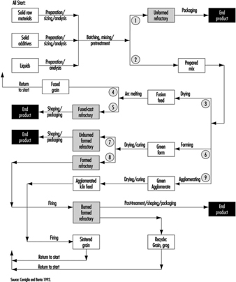
These generic flow diagrams represent thousands of specific processes, differentiated, for example, by their raw materials lists, the manner of preparation and the sizing and batching (meaning quantity weighed out) of each, the sequence and manner of mixing and so on. Omissions are allowed—for example, some unformed refractories are dry-mixed and never wetted until installation.
Refractories or products may be preformed (shaped) or formed and installed on site, but in general are supplied in the following shapes:
Brick. The standard dimensions of a refractory brick are 23 cm long by 11.4 cm wide and 6.4 cm thick (straight brick). Bricks may be extruded or dry-pressed on mechanical or hydraulic presses. Formed shapes may be burned before use or, in the case of pitch, resin or chemically bonded brick (cured).
Fusion-cast shapes. Refractory compositions are arc-melted and cast into shapes (e.g., glass-tank flux blocks as large as 0.33, 0.66, 1.33 m). After casting and annealing, the blocks are accurately ground to ensure a precise fit.
Cast and hand-moulded refractories. Large shapes, such as burner blocks and flux blocks, and intricate shapes, such as glass feeder parts, saggers and the like, are produced by either slip or hydraulic cement casting or hand-moulding techniques. Because these techniques are labour intensive, they are reserved for articles that cannot be satisfactorily formed in other ways.
Insulating refractories. Insulating refractories in the form of brick are much lighter than conventional brick of the same composition by virtue of the brick porosity.
Castables and gunning mixes. Castables consist of refractory grains to which a hydraulic binder is added. Upon mixing with water, the hydraulic agent reacts and binds the mass together. Gunning mixes are designed to be sprayed through a nozzle under water and air pressure. The mixture may be slurried before being shot through the gun, or mixed with water at the nozzle.
Plastic refractories and ramming mixes. Plastic refractories are mixtures of refractory grains and plastic clays or plasticizers with water. Ramming mixes may or may not contain clay and are generally used with forms. The amount of water used with these products varies but is held to a minimum.
Occupational Hazards and Precautions
Table 5 provides information on many of the potential hazards found in this industrial sector.
Table 5. Potential health and safety hazards found during manufacturing of glass, ceramic and related materials
|
Hazards |
Uses or sources of exposure |
Potential effects (physical hazards |
Precautions or control strategies |
|
Ergonomic stressors; biomechanical hazards |
Overexertion from manual material-handling practices and excessive force, poor posture, high frequency/duration of tasks involving lifting, pushing or pulling |
Strains, sprains and run in skeletal muscular damage to back, upper and lower extremities Excessive physical and mental fatigue can cause errors leading to secondary incidents |
|
|
Physical hazards |
Caught in or struck by or against fixed or mobile equipment Slips, trips and falls on walking and working surfaces, hoses and other equipment, tools or materials |
Abrasions, cuts, contusions, lacerations, punctures, fractures, amputations |
|
|
Noise |
Pneumatic vibrators, compressors, valve actuators, mixing drive motors, blowers and dust collectors, conveyors, powered industrial trucks, mechanized process and packaging equipment, etc. |
Occupational hearing loss, communication difficulty and stress |
|
|
Radiant heat, high-temperature work environments |
Heating or melting processes during maintenance or emergency response activities |
Physiological strain, heat stress or thermal burns |
|
|
Inhalation of airborne particulate matter from raw materials including crystalline silica, clay, lime, iron oxide, nuisance dusts |
Handling raw materials and during production Exposures during routine maintenance activities, demolition and during construction activities or rebuilds Exposures can occur from non-ventilated equipment or from leaks or poor seals at transfer points, chutes, conveyors, elevators, screens, sieves, mixing equipment, grinding or crushing machines, storage bins, valves, piping, drying or curing ovens, shaping operations, etc. Raw materials are extremely abrasive, causing deterioration of transfer or storage system components in manufacturing processes. Failure to maintain baghouses, scrubbers or dust collectors and use of compressed air for clean-up activities increases risk of overexposures Intense heating processes may lead to exposure to the most hazardous forms of silica (cristobalite or tridymite) |
Range from irritation (nuisance particulate) to chemical burns (burnt lime or other alkaline raw materials) to chronic effects such as decreased pulmonary function, lung disease, pneumoconiosis silicosis, tuberculosis |
|
|
Lacerations, abrasions, or foreign bodies; contact with sharp glass, pottery or ceramics fragments or objects |
Flying glass, ceramics or other fragments may cause penetrating wounds and serious eye injury. A special risk exists when toughened glass “explodes” during manufacture Direct contact with glass or other filaments, especially in forming or winding in continuous filament production operations and coating Drawing operations in optical fibre manufacturing |
Puncture wounds, lacerations or abrasion of skin and soft tissues (tendons, ligaments, nerves, muscle), and foreign bodies in the eye Risks of serious secondary infections or dermal exposures to corrosive or toxic materials |
|
|
Lacerations from hand-tools |
Razor knives, finger knives, cullet knives or other sharp hand tools are commonly used in production, packaging and warehousing areas or during maintenance activities |
Cuts to finger(s) or hand(s) and to lower extremities (legs) |
|
|
Heavy metals particulates or fumes (lead, cadmium, chromium, arsenic, copper, nickel, cobalt, manganese or tin) |
As raw materials or impurities in glazes, product formulas, pigments, colouring agents, films or coatings Maintenance and construction activities involving soldering, cutting, welding and applying/ removal of protective coatings Grinding, cutting, welding, drilling, or shaping fabricated metal parts, structural members or machinery (e.g., refractory blocks or high-temperature alloys) that are components of manufacturing processes |
Heavy metal toxicity |
|
|
Formaldehyde via inhalation or direct contact |
Component of binders and sizes in vitreous fibre industry Potential exposures during mixing of binders or sizes, and during production |
Sensory irritation, and irritation of respiratory tract Probable human carcinogen |
|
|
Bases (sodium hydroxide) or acids (hydrochloric acid, sulphuric acid, hydro-fluoric acid) |
Process water, boiler water or wastewater treatment and pH control Acid cleaning or etching processes with hydrofluoric acid |
Corrosive to skin or eyes Respiratory tract and mucous membrane irritant Hydrofluoric acid causes severe shin burns that can go undetected for hours |
|
|
Epoxies, acrylates and urethanes (may contain solvents such as xylene, toluene, etc.) |
Ingredients in resins, sizes, binders and coatings used in production Maintenance products |
Potential sensitizers to skin or respiratory tract Some epoxies contain unreacted epichlorohydrin, a suspect carcinogen Some urethanes contain unreacted toluene diisocyanate, a suspected carcinogen Amine curatives used in some systems—irritants or corrosives Flammability hazard |
|
|
Styrene |
Polyester resins containing styrene, size ingredients |
Irritant to eyes, skin, respiratory tract; effects on central nervous system (CNS) and target organs Possible carcinogen Flammability hazard |
|
|
Silanes |
Adhesion promoters added to sizes, binders or coatings. Can hydrolyze to release ethanol, methanol, butanol or other alcohols |
Irritant to eyes, skin and respiratory system; potential CNS effects. Splashes in eye can cause permanent damage Flammability hazard |
|
|
Latex |
Size or binder mixing areas, coatings and some maintenance products |
Irritant to skin and eyes. Some may contain formaldehyde or other biocides and/or solvents |
|
|
Catalysts and accelerators |
Added to resins or binders for curing in production and/or for some maintenance products |
Irritants or corrosives to skin or eyes. Some are highly reactive and temperature sensitive |
|
|
Hydrocarbon solvents and/or chlorinated solvents |
Maintenance shops and parts-cleaning operations |
Various—irritation, chemical dermatitis, CNS effects. Non-chlorinated solvents may be flammable Chlorinated solvent can decompose if burned or heated |
|
|
Propane, natural gas, gasoline, fuel oil |
Fuels for process heat Fuels for powered industrial trucks |
Fire and explosion hazards Exposure to carbon monoxide or other products of incomplete combustion |
|
|
Inhalation of bioaerosols |
Aerosols containing bacteria, moulds or fungus generated from spraying process or cooling water in humidification processes, cooling towers, ventilation systems, wet clean-up activities |
Waterborne illness with systemic non specific flu-like symptoms, fatigue Potential for dermatitis |
|
|
Fibrous glass, mineral wool fibre, refractory ceramic fibres |
In manufacturing processes including fibre formation, heat curing, cutting or cubing, winding, packaging and fabrication In use of fibrous materials as a component of furnaces, ducts and process equipment |
Non-respirable fibres can cause mechanical irritation to skin or eyes Respirable fibres can cause irritation to eyes, skin and respiratory tract. Durable fibres have caused fibrosis and tumours in animal studies |
|
Safety and Health Problems and Disease Patterns
This section provides an overview of industry-wide documented or suspected safety and health problems. International data on injuries and illnesses in this business sector were not located in literature searches and searches on the Internet (in 1997). Information compiled by the US Department of Labor, Occupational Safety and Health Administration (OSHA) and Bureau of Labor Statistics (BLS), was used to identify common hazards in the workplace and to describe characteristics of injuries and illnesses. These data should be representative of the situation worldwide.
Hazards detected during inspections
Regulatory compliance inspections of companies in the stone, clay, glass and concrete products manufacturing (Standard Industrial Classification (SIC) Code 32, equivalent to ISIC Code 36) reveal some of the common hazards in this sector. Regulatory compliance citations issued by OSHA indicate that common health and safety issues can be grouped as follows:
- hazard communication of physical and health hazards of chemical substances in the workplace
- control of hazardous energy—lockout and tagout procedures to control activities around machinery or equipment where un-expected energization or release of stored energy could cause injury. Hazardous energy includes electrical, mechanical, hydraulic, pneumatic, chemical, thermal radiation and other sources.
- electrical safety, including electrical equipment or system design, wiring methods, safe work practices and training
- permit required confined-space entry—identification, evaluation and safe entry procedures
- personal protective equipment—assessments, selection and use of eye, face, hand, foot and head protection
- guarding machines, equipment and tools to protect operators and adjacent workers from hazards at point of operation, ingoing nip points, and from rotating parts, flying chips or sparks; includes fixed machinery, portable machinery and portable power tools, and adjustment of guards and work rests on abrasive wheel machinery (grinders) (see figure 18)
Figure 18. Machine guarding protects operators
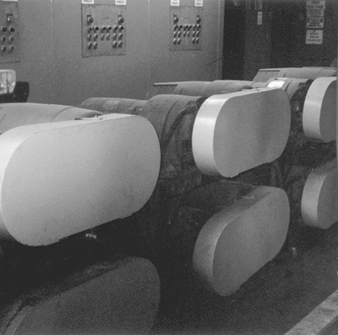
- respiratory protection—selection, use, maintenance, training, medical clearance and fit testing of respirators
- occupational noise exposure—control of exposures by engineering, administrative or hearing protection and implementation of hearing conservation programmes
- fire prevention and emergency preparedness and response, including fire extinguishers, escape routes, plans and flammable/combustible materials storage or use
- walking and working surfaces, including guarding floor and wall openings and holes; housekeeping; and keeping aisles and passageways free from conditions that present slip, trip or fall hazards (see figure 19)
Figure 19. Trip & slip hazards
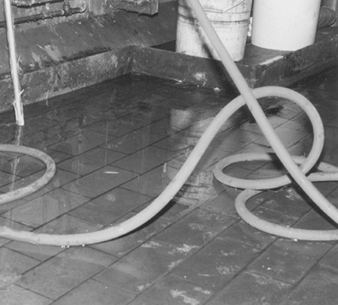
- powered industrial trucks—design, maintenance, use and other safety requirements for fork-lift trucks, platform trucks, tractors, motorized hand trucks or other specialized industrial trucks powered by electric motors or internal combustion motors
- fixed and portable ladders, stairways and scaffolds—design, inspection or maintenance and safe use
- fall protection—use of fall restraints and arrest equipment for elevated work
- cutting and welding—safe use and procedures for oxygen/acetylene or fuel gas or arc cutting or welding equipment
- material-handling equipment—including overhead and gantry cranes, hoists, chains and slings
- control of exposure to toxic or hazardous substances, including air contaminants or specifically regulated chemicals (e.g., silica, lead, asbestos, formaldehyde, cadmium or arsenic).
Injury and Illness Profile
Injury illness incidence rates
Based on records from the US Department of Labor, manufacturers of stone, clay and glass products (SIC 32) have a total “recordable” incidence rate of nonfatal occupational injuries and illnesses of 13.2 cases per 100 full-time workers per year. This incidence rate is higher than corresponding rates for all manufacturing (12.2) and all private industry (8.4). About 51% of the “recordable injury” cases in the stone, clay and glass product manufacturing sector do not result in lost work days (time away from work).
The “total lost workday case” incidence rates based on the number of disabling injuries or illnesses resulting in a worker missing days of work per 100 full-time workers are also available from the US Department of Labor. The total lost workday incidence rate includes cases where workdays are lost and the worker is not capable of performing the full scope of the job (restricted or light duty). Stone, clay and glass products manufacturers have a total lost workday incidence rate of 6.5 cases per 100 workers per year. This is higher than the corresponding rates for all manufacturing (5.5) and for all private industry (3.8). About 93% of the lost workday cases in the stone, clay and glass product manufacturing sector results from injuries rather than occupational illnesses.
Table 6 presents more detailed information on incidence rates for injuries and illnesses (combined) or injuries (alone) for various types of manufacturing processes within the stone, clay, and glass product manufacturing sector (SIC Code 32). Incidence rates and demographics may not be representative of global information, but it is the most complete information available.
Table 6. Nonfatal occupational injury and illness incidence rates1 per 100 full-time workers for US companies in SIC Code 32, private industry and manufacturing, 1994
|
Industry |
SIC Code2 |
1994 Annual Average Employment3 (thousands) |
Injuries and Illnesses |
Injuries |
||||||
|
Lost Workday Cases |
Lost Workday Cases |
|||||||||
|
Total Cases |
Total4 |
With days away from work |
Cases without Lost Workdays |
Total Cases |
Total5 |
With days away from work5 |
Cases without Lost workdays |
|||
|
Private industry, all |
95,449.3 |
8.4 |
3.8 |
2.8 |
4.6 |
7.7 |
3.5 |
2.6 |
4.2 |
|
|
Manufacturing, all |
18,303.0 |
12.2 |
5.5 |
3.2 |
6.8 |
10.4 |
4.7 |
2.9 |
5.7 |
|
|
Stone, clay and glass products |
32 |
532.5 |
13.2 |
6.5 |
4.3 |
6.7 |
12.3 |
6.1 |
4.1 |
6.2 |
|
Flat glass |
321 |
15.0 |
21.3 |
6.6 |
3.1 |
14.7 |
17.3 |
5.2 |
2.6 |
12.1 |
|
Glass and glassware, pressed |
322 |
76.8 |
12.5 |
6.0 |
3.0 |
6.5 |
11.3 |
5.5 |
2.8 |
5.8 |
|
Glass containers |
3221 |
33.1 |
14.1 |
6.9 |
3.4 |
7.2 |
13.2 |
6.5 |
3.2 |
6.7 |
|
Pressed and blown glass, nec |
3229 |
43.7 |
11.3 |
5.4 |
2.8 |
5.9 |
9.8 |
4.8 |
2.4 |
5.1 |
|
Products of purchased glass |
323 |
60.7 |
14.1 |
6.1 |
3.1 |
8.0 |
12.7 |
5.4 |
2.9 |
7.4 |
|
Structural clay products |
325 |
32.4 |
14.1 |
7.7 |
4.2 |
6.5 |
13.1 |
7.2 |
4.0 |
5.9 |
|
Brick and structural clay tile |
3251 |
- |
15.5 |
8.4 |
5.1 |
7.1 |
14.8 |
7.9 |
5.0 |
6.9 |
|
Clay refractories |
3255 |
- |
16.0 |
9.3 |
4.7 |
6.8 |
15.6 |
9.3 |
4.7 |
6.4 |
|
Pottery and related products |
326 |
40.8 |
13.6 |
6.8 |
3.8 |
6.8 |
12.2 |
6.1 |
3.5 |
6.1 |
|
Vitreous plumbing fixtures |
3261 |
- |
17.8 |
10.0 |
3.8 |
7.8 |
16.1 |
9.0 |
3.5 |
7.1 |
|
Vitreous china table and |
3262 |
- |
12.8 |
6.3 |
4.4 |
6.5 |
11.0 |
5.6 |
3.8 |
5.5 |
|
Porcelain electrical supplies |
3264 |
- |
11.3 |
5.8 |
3.7 |
5.6 |
9.8 |
5.0 |
3.4 |
4.8 |
|
Pottery products, nec |
3269 |
- |
12.6 |
5.6 |
3.7 |
7.1 |
11.6 |
5.0 |
3.5 |
6.6 |
|
Concrete, gypsum and plaster |
327 |
198.3 |
13.4 |
7.0 |
5.6 |
6.4 |
13.0 |
6.9 |
5.5 |
6.2 |
|
Concrete block and brick |
3271 |
17.1 |
14.5 |
7.8 |
6.8 |
6.8 |
14.0 |
7.7 |
6.7 |
6.2 |
|
Concrete products, nec |
3272 |
65.6 |
17.7 |
9.8 |
7.0 |
7.9 |
17.1 |
9.5 |
6.8 |
7.6 |
|
Ready-mixed concrete |
3273 |
98.8 |
11.6 |
6.0 |
5.3 |
5.6 |
11.5 |
6.0 |
5.3 |
5.5 |
|
Misc. nonmetallic mineral |
329 |
76.7 |
10.7 |
5.4 |
3.3 |
5.3 |
9.8 |
5.0 |
3.2 |
4.9 |
|
Abrasive products |
3291 |
20.0 |
10.2 |
3.9 |
2.5 |
6.3 |
9.5 |
3.7 |
2.4 |
5.8 |
|
Mineral wool |
3296 |
23.4 |
11.0 |
6.1 |
3.0 |
4.9 |
10.0 |
5.6 |
2.7 |
4.3 |
|
Nonclay refractories |
3297 |
- |
10.6 |
5.8 |
4.5 |
4.8 |
10.2 |
5.7 |
4.3 |
4.6 |
|
Nonmetallic mineral products, |
3299 |
- |
13.1 |
8.2 |
5.8 |
4.9 |
11.4 |
7.0 |
5.5 |
4.3 |
nec = not elsewhere classified
- = data not available
1 The incidence rates represent the number of injuries and illnesses per 100 full-time workers and were calculated as number of injuries and illnesses divided by hours worked by all employees in the calendar year times 200,000 (the base equivalent for 100 workers at 40 hours per week for 52 weeks per year).
2 Standard Industrial Classification Manual 1987 Edition.
3 Employment is expressed as an annual average and was derived primarily from the BLS State Current Employment Statistics programme.
4 Total cases includes cases involving restricted work activity only, in addition to days away from work cases with or without restricted work activity.
5 Days away from work cases include those which result from days away from work, with or without restricted work activity.
Source = Source: Based on national survey of work-related injuries and illnesses in private industry by the US Department of Labor, Bureau of Labor Statistics.
Demographics of injuries and illness cases
Workers aged 25 to 44 years accounted for about 59% of the 23,203 lost-time injury or illness cases in the U.S. stone, clay and glass product manufacturing sector. The next highest affected group was workers aged 45 to 54 years, who had 18% of the lost-time injury or illness cases (see figure 20).
Figure 20. Lost-time injuries & illnesses by age; US
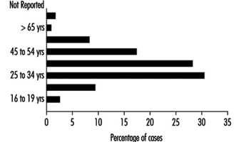
About 85% of the lost-time injury cases injuries and illnesses in SIC Code 32 were males. In 24% of the lost-time cases (both sexes), workers had less than 1 year of service in the job. Workers with 1 to 5 years of service in the job accounted for 32% of the cases. Experienced employees with more than 5 years of service comprised 35% of the lost-time cases.
Nature. Analysis of lost-time incident profiles characterizes the nature of the disabling injuries and illnesses and helps explain causative or contributing factors. Strains and sprains are the leading nature of injury and illness in the stone, clay and glass product manufacturing sector. As shown in figure 23, strains and sprains make up about 42% of all lost-time cases. Cuts and punctures (10%) were the second most common nature of disabling injury or illness. Other major nature of injury categories were bruises (9%), fractures (7%) and back/other pain (5%). Heat burns, chemical burns and amputations were less common (1% or less).
Figure 21. Occupational injuries & illnesses
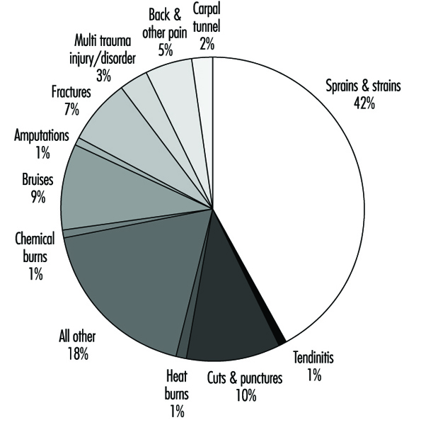
Events or exposures. Figure 22 shows that overexertion while lifting leads all other disabling injury events or exposures. Over exertion while lifting was a causative factor in about 17% of the disabling cases; repetitive motion was the exposure in an additional 5% of the disabling cases. Struck by an object was the next most common event, which led to 16% of the cases. Struck against an object events caused 10% of the cases. Other important events were caught in an object (9%), falls on same level (9%), falls to lower level (6%), and slips/trips without a fall (6%). Exposure to harmful substances or environment was a causative factor in only 5% of the cases.
Figure 22. Event or exposure in occupational injuries
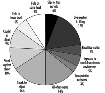
Body part. The body part most frequently affected was the back (24% of the cases) (see figure 23). Injuries to the upper extremities (finger, hand, wrist and arm combined) occurred in 23% of the cases, with injury to the finger in 7% of the cases. Lower-extremity injuries was similar (22% of cases), with the knee affected in 9% of the cases.
Figure 23. Body part affected in lost workday injury
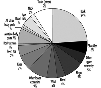
Sources. The most common sources of disabling injury or illness cases were: parts and materials (20%); worker position or motion (16%); floors, walkways or ground surfaces (15%); containers (10%); machinery (9%); vehicles (9%); handtools (4%); furniture and fixtures (2%); and chemicals and chemical products (2%) (see figure 24).
Figure 24. Sources of occupational injuries
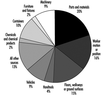
Disease prevention and control
Cumulative trauma associated with repetitive motion, overexertion and excessive forces is a common finding in this manufacturing sector. Robotic devices are available in some instances, but manual handling practices still dominate. Compressors, blowers, spinners, pneumatic vibrators and packaging equipment can create noise exceeding 90 to 95 dBA. Hearing protection and a sound hearing conservation programme will prevent permanent changes in hearing.
This industry consumes large quantities of crystalline silica. Exposures must be limited during handling, maintenance and cleaning. Good housekeeping with a proper vacuum system or wet cleaning methods will reduce potential exposures. Periodic screening should be conducted utilizing pulmonary function tests and chest films if excessive exposure to silica has occurred. Exposures to heavy metals found as raw materials, glazing or pigments should also be minimized. Using substitutes for heavy metals found in glazes will also eliminate health concerns regarding leaching of metals into food or beverages. Good housekeeping practices and respiratory protection are used to prevent adverse effects. Medical surveillance that includes biological monitoring may be necessary.
The use of binders containing formaldehyde, epoxies and silanes is common in the manufacture of vitreous fibres. Steps must be taken to minimize skin and respiratory irritation. Formaldehyde is regulated as a carcinogen in many countries. Respirable fibres are produced during manufacturing, fabrication, cutting and installation of glass, rock, slag, and refractory ceramic fibre products. Although exposures to airborne fibres have generally been quite low (less than 1 fibre per cubic centimetre) for most of these materials, loose fill blowing applications tend to be much higher.
Rock, slag, and glass are among the most extensively studied commercial insulation products in use today. Epidemiological studies have revealed that cigarette smoking is having a major impact on lung cancer mortality among manufacturing employees. Well-conducted cross-sectional studies have not shown that the fibres produce excess lung mortality or morbidity. Recent chronic inhalation studies in rats have shown that the durability of vitreous fibres is a critical determinant of the biological potential of these fibres. Composition, which determines the durability of these fibres, may vary considerably. To avoid public health concerns, a European Commission Technical Committee has recently proposed that the bio-persistence of vitreous fibres be tested using short-term inhalation. An insulation wool composition which has been thoroughly tested at maximum tolerated dose by chronic inhalation in rats and found not to produce irreversible disease is suggested as a reference fibre.
Environmental and Public Health Issues
The primary air pollutant emitted during the manufacture of glass, ceramics, pottery and brick is particulate matter. Maximum achievable control technology consisting of baghouses and wet electrostatic precipitators is available to reduce emissions when necessary. Hazardous air pollutants generated during binder mixing, application and curing processes are coming under scrutiny. These substances include styrene, silanes and epoxies used on continuous glass filament, and formaldehyde, methanol and phenol utilized during rock, slag and glass production. Formaldehyde is the hazardous air pollutant that is driving the control standards for the latter manufacturing lines. Heavy metal hazardous air pollutants such as chromium are driving glass melting furnace standards while NOx and SOx remain issues in some countries. Fluoride and boron emissions are of concern in continuous glass filament production. Boron may also become an environmental concern if highly soluble vitreous glass wool fibres are required in some countries.
Due to the high discharge volume of air and the nature of forming and glass melting, the industry evaporates considerable quantities of water. Many facilities, as, for example, in the United States, have zero discharge of wastewater. Recycled wastewater that contains organic material can create biological hazards in the workplace if treatment is not implemented to prevent biological growth (see figure 25). Waste generated by this industrial sector includes heavy metals, corrosives, some binders and spent solvents. The glass fibre industry has become a major point for recycling glass bottles and plate glass. For example, current glass wool products contain 30 to 60% recycled glass. Spent refractories are also reclaimed and beneficially reused.
Figure 25. Aerosols of reused waste water
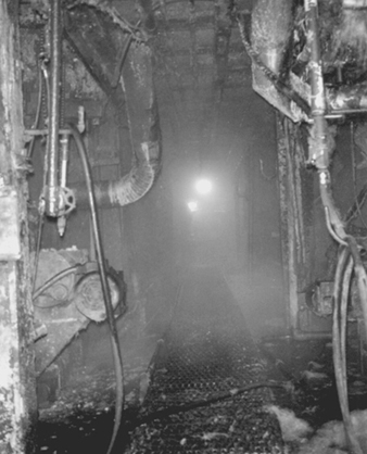
Acknowledgements: Special thanks to Dan Dimas, CSP, Libbey-Owens-Ford, for providing photographs, and to Michel Soubeyrand, Libbey-Owens-Ford, for providing information on chemical vapour deposition for the section on glass.
Optical Fibres
Optical fibres are hair-thin strands of glass designed to transmit light rays along their axis. Light-emitting diodes (LEDs) or laser diodes convert electrical signals into the optical signals that are transmitted through an inner cylindrical core of the optical fibre cable. The lower refractive properties of the external cladding allows light signals to be propagated by internal reflection along the inner cylindrical core. Optical fibres are designed and manufactured to propagate either as a single light beam or as multiple light beams simultaneously transmitted along the core. (See figure 1.)
Figure 1. Single & multi-mode optical fibres
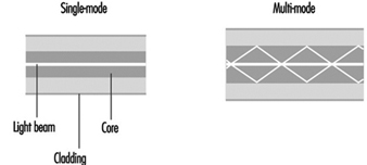
Single-mode fibre is primarily used for telephony, cable television applications and campus backbones. Multi-mode fibre is commonly used for data communications and in premise networks.
Optical fibre manufacturing
Special materials and processes are required to manufacture optical fibres that meet the basic design criteria: (1) a core with a high refractive index and cladding with a low refractive index, (2) a low signal attenuation or power loss, and (3) a low dispersion or broadening of the light beam.
High-purity silica glass with other glass materials (i.e., heavy-metal fluoride glasses, chalcogenide glasses) are the primary materials currently used to manufacture optical fibres. Polycrystalline materials, single-crystal materials, hollow waveguides and polymeric plastic materials are also used. Raw materials must be relatively pure with very low concentrations of transition metals and hydroxyl-forming groups (below the parts per billion level). Processing methods must shield the forming glass from impurities in the manufacturing environment.
Optical fibres are manufactured by using a non-conventional vapour phase preparation of a glass preform which is then drawn into fibre. Volatile silica compounds are converted to SiO2 by flame hydrolysis, chemical vapour deposition (CVD) or high-temperature oxidation. Other dopants are then added to the glass to change the glass properties. Variations in the process of vapour deposition start with the same material but differ in the method used to convert this material to silica.
One of the following vapour phase deposition methods is used to manufacture silica-based optical fibres: (1) modified chemical vapour deposition (MCVD), (2) plasma chemical vapour deposition (PCVD), (3) outside vapour deposition (OVD), and (4) vapour phase axial deposition (VAD) (see figure 2). Silicon tetrachloride (SiCI4), germanium tetrachloride (GeCI4) or other volatile liquid halides convert to gas when heated slightly due to their high vapour pressures. Gaseous halide is delivered to a reaction zone and converted to glass particles (see also the chapter Microelectronics and semiconductors.)
Figure 2. Optic fibre manufacturing flow chart
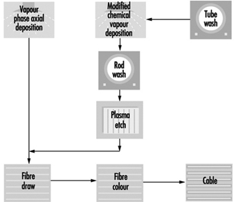
MCVD and PCVD processes. A high-quality fused silica tube is attached to a glass working lathe fitted with a hydrogen/oxygen torch that traverses its length. A halide material supply is attached to one end of the glass tube and a scrubber to the opposite end to remove excess halide material. The surface of the glass tube is first cleaned by fire polishing as the torch traverses the tube’s length. Various reagents are added in the vapour system depending on the product being manufactured. A chemical reaction occurs as the halides pass through the section of the tube being heated. The halides convert to silica “soot” particles that deposit on the inner glass tube wall downstream from the torch. Deposited particles are sintered into the glass layer. The PCVD process is similar to MCVD except that the halides are supplied by a bubbler system, and microwaves are used instead of a torch to convert the halide material to glass.
OVD and VAD processes. In the first stage of the fibre manufacturing process, the core and cladding glasses are vapour deposited around a rotating target rod to form a “soot” preform. The core material is deposited first, followed by the cladding. The entire preform must be extremely pure, since both the core and cladding are vapour deposited. Fibre geometry is determined during the laydown phase of manufacturing. After the target rod is removed, the preform is placed in a furnace, where it is consolidated into a solid, clear glass and the centre hole is closed. Gas is passed through the preform to remove residual moisture which adversely affects the attenuation of the fibre (loss of optical signal as light transmits along the fibre axis). Preforms are then washed with hydrofluoric acid to ensure the purity of the glass and to remove contaminants.
The consolidated glass preform is placed in a draw tower to form a continuous strand of glass fibre. First the preform is loaded into the top of a draw furnace. Next, the tip of the preform is heated and a piece of molten glass begins to fall. As this piece is drawn (pulled), it passes through an inline diameter monitor to assure the fibre meets an exact specified diameter (usually measured in microns.) The fibre’s cladding diameter must conform with exact specifications in order to keep signal loss at connections low. The outer cladding diameter is used as a guide to align fibre cores during end use. The cores must line up so light transfer occurs efficiently.
Acrylate polymer or other coatings are applied and cured with ultraviolet lamps. The coatings are intended to protect the optical fibre from the environment during end use. The optical fibres are tested to assure conformance with manufacturing standards for strength, attenuation and geometry. Specific lengths of fibre are wound onto reels per customer specifications.
A number of potential hazards are encountered during optical fibre manufacturing. These include: (1) exposure to hydrofluoric acid (when cleaning glass preforms), (2) radiant energy and heat stress associated with working environments near lathes and vapour deposition processes, (3) direct contact with hot surfaces or molten material (glass preforms), (4) exposure to acrylate polymer coatings (skin sensitizers), (5) skin punctures and lacerations during fibre handling and (6) a variety of physical hazards previously described.
Synthetic Gems
Synthetic gems are chemically and structurally identical to stones found in nature. Imitation gems, in contrast, are stones that are made to appear similar to a particular gem. There are a few basic processes that produce a variety of gem stones. Synthetic gems include garnet, spinel, emerald, sapphire and diamond. Most of these stones are produced for use in jewellery. Diamonds are used as abrasives, while rubies and garnets are used in lasers.
The first synthetic gem used in jewellery was emerald. The process employed in its manufacture is proprietary and kept secret, but probably involves a flux-growth method in which silicates of alumina and beryllium with additions of chromium for colour are melted together. Emeralds crystallize out of the flux. It may take a year to produce stones by this process.
The Verneuil or flame-fusion process is used in the production of sapphire and ruby. It requires large amounts of hydrogen and oxygen, therefore consuming great amounts of energy. This process involves heating a seed crystal with an oxyhydrogen flame until the surface is liquid. Powered raw material such as AI2O3 for sapphire is added carefully. As the raw material becomes molten, the seed crystal is slowly withdrawn from the flame, causing the liquid furthest from the flame to solidify. The end closest to the flame is still liquid and ready for more raw material. The end result is the formation of a rod-like crystal. Sundry colours are created by adding small amounts of various metal ions to the raw materials. Ruby is created by replacing 0.1% of its aluminium ions with chromium atoms.
Spinel, a colourless synthetic germ (MgAI2O4), is made by the Verneuil process. Along with sapphire, spinel is used by industry to provide a wide range of colours for use as birth stones and in class rings. The colour produced by adding the same metal ions will be different in spinel than it will be in sapphire.
Synthetic diamonds are used in industry because of their hardness. Applications for diamonds include cutting, polishing, grinding and drilling. Some of the common uses are cutting and grinding of granite for use in building construction, well drilling and grinding non-ferrous alloys. In addition, processes are being developed that will deposit diamond on surfaces to provide clear, hard, scratch-resistant surfaces.
Diamonds are formed when elemental carbon or graphite is subjected to pressure and heat over time. To create a diamond on the factory floor involves combining graphite and metal catalysts and pressing them together in high heat (up to 1,500 °C). The size and quality of the diamonds are controlled by adjusting the time, pressure and/or heat. Large tungsten carbide dies are used to achieve the high pressures needed to form diamonds in a reasonable period of time. These dies measure up to 2 m across and 20 cm thick, resembling a large doughnut. The mixture of graphite and catalyst is placed in a ceramic gasket, and tapered pistons squeeze from above and below. After a specified time, the gasket containing diamonds is removed from the press. The gaskets are broken away and the diamond-bearing graphite is subjected to a series of agents designed to digest away all material except for the diamonds. The reactants employed are strong agents that are potential sources of significant burns and respiratory injury. Gem-quality diamonds may be produced in the same manner, but the long press times required make this process prohibitively expensive.
Hazards resulting from the manufacture of diamonds include potential exposure to the highly reactive acids and caustic agents in great volumes, noise, dust from forming and breaking of ceramic gaskets, and metal dust exposure. Another potential hazard is created by the failure of the massive carbide dies. After a variable number of uses, the dies fail, posing a trauma hazard if the dies are not isolated. Ergonomic issues arise when the diamonds manufactured are classified and graded. Their small size makes this a tedious and repetitive job.
" DISCLAIMER: The ILO does not take responsibility for content presented on this web portal that is presented in any language other than English, which is the language used for the initial production and peer-review of original content. Certain statistics have not been updated since the production of the 4th edition of the Encyclopaedia (1998)."