- You are here:
-
Home

-
Part VIII. Accidents and Safety Management
-
Safety Applications
- Moving Parts of Machines

58. Safety Applications
Chapter Editors: Kenneth Gerecke and Charles T. Pope
Table of Contents
Tables and Figures
Systems Analysis
Manh Trung Ho
Hand and Portable Power Tool Safety
US Department of Labor—Occupational Safety and Health Administration; edited by Kenneth Gerecke
Moving Parts of Machines
Tomas Backström and Marianne Döös
Machine Safeguarding
US Department of Labor— Occupational Safety and Health Administration; edited by Kenneth Gerecke
Presence Detectors
Paul Schreiber
Devices for Controlling, Isolating and Switching Energy
René Troxler
Safety-Related Applications
Dietmar Reinert and Karlheinz Meffert
Software and Computers: Hybrid Automated Systems
Waldemar Karwowski and Jozef Zurada
Principles for the Design of Safe Control Systems
Georg Vondracek
Safety Principles for CNC Machine Tools
Toni Retsch, Guido Schmitter and Albert Marty
Safety Principles for Industrial Robots
Toni Retsch, Guido Schmitter and Albert Marty
Electrical, Electronic and Programmable Electronic Safety-Related Control Systems
Ron Bell
Technical Requirements for Safety-Related Systems Based on Electrical, Electronic and Programmable Electronic Devices
John Brazendale and Ron Bell
Rollover
Bengt Springfeldt
Falls from Elevations
Jean Arteau
Confined Spaces
Neil McManus
Principles of Prevention: Materials Handling and Internal Traffic
Kari Häkkinen
Tables
Click a link below to view table in article context.
1. Possible dysfunctions of a two-button control circuit
2. Machine guards
3. Devices
4. Feeding & ejection methods
5. Circuit structures’ combinations in machine controls
6. Safety integrity levels for protection systems
7. Software design & development
8. Safety integrity level: type B components
9. Integrity requirements: electronic system architectures
10. Falls from elevations: Quebec 1982-1987
11.Typical fall prevention & fall arrest systems
12. Differences between fall prevention & fall arrest
13. Sample form for assessment of hazardous conditions
14. A sample entry permit
Figures
Point to a thumbnail to see figure caption, click to see figure in article context.
|
|


Systems Analysis
A system can be defined as a set of interdependent components combined in such a way as to perform a given function under specified conditions. A machine is a tangible and particularly clear-cut example of a system in this sense, but there are other systems, involving men and women on a team or in a workshop or factory, which are far more complex and not so easy to define. Safety suggests the absence of danger or risk of accident or harm. In order to avoid ambiguity, the general concept of an unwanted occurrence will be employed. Absolute safety, in the sense of the impossibility of a more or less unfortunate incident occurring, is not attainable; realistically one must aim for a very low, rather than a zero probability of unwanted occurrences.
A given system may be looked upon as safe or unsafe only with respect to the performance that is actually expected from it. With this in mind, the safety level of a system can be defined as follows: “For any given set of unwanted occurrences, the level of safety (or unsafeness) of a system is determined by the probability of these occurrences taking place over a given period of time”. Examples of unwanted occurrences that would be of interest in the present connection include: multiple fatalities, death of one or several persons, serious injury, slight injury, damage to the environment, harmful effects on living beings, destruction of plants or buildings, and major or limited material or equipment damage.
Purpose of the Safety System Analysis
The object of a system safety analysis is to ascertain the factors which have a bearing on the probability of the unwanted occurrences, to study the way in which these occurrences take place and, ultimately, to develop preventive measures to reduce their probability.
The analytic phase of the problem can be divided into two main aspects:
- identification and description of the types of dysfunction or maladjustment
- identification of the sequences of dysfunctions that combine one with another (or with more “normal” occurrences) to lead ultimately to the unwanted occurrence itself, and the assessment of their likelihood.
Once the various dysfunctions and their consequences have been studied, the system safety analysts can direct their attention to preventive measures. Research in this area will be based directly on earlier findings. This investigation of preventive means follows the two main aspects of the system safety analysis.
Methods of Analysis
System safety analysis may be conducted before or after the event (a priori or a posteriori); in both instances, the method used may be either direct or reverse. An a priori analysis takes place before the unwanted occurrence. The analyst takes a certain number of such occurrences and sets out to discover the various stages that may lead up to them. By contrast, an a posteriori analysis is carried out after the unwanted occurrence has taken place. Its purpose is to provide guidance for the future and, specifically, to draw any conclusions that may be useful for any subsequent a priori analyses.
Although it may seem that an a priori analysis would be very much more valuable than an a posteriori analysis, since it precedes the incident, the two are in fact complementary. Which method is used depends on the complexity of the system involved and on what is already known about the subject. In the case of tangible systems such as machines or industrial facilities, previous experience can usually serve in preparing a fairly detailed a priori analysis. However, even then the analysis is not necessarily infallible and is sure to benefit from a subsequent a posteriori analysis based essentially on a study of the incidents that occur in the course of operation. As to more complex systems involving persons, such as work shifts, workshops or factories, a posteriori analysis is even more important. In such cases, past experience is not always sufficient to permit detailed and reliable a priori analysis.
An a posteriori analysis may develop into an a priori analysis as the analyst goes beyond the single process that led up to the incident in question and starts to look into the various occurrences that could reasonably lead to such an incident or similar incidents.
Another way in which an a posteriori analysis can become an a priori analysis is when the emphasis is placed not on the occurrence (whose prevention is the main purpose of the current analysis) but on less serious incidents. These incidents, such as technical hitches, material damage and potential or minor accidents, of relatively little significance in themselves, can be identified as warning signs of more serious occurrences. In such cases, although carried out after the occurrence of minor incidents, the analysis will be an a priori analysis as regards more serious occurrences that have not yet taken place.
There are two possible methods of studying the mechanism or logic behind the sequence of two or more events:
- The direct, or inductive, method starts with the causes in order to predict their effects.
- The reverse, or deductive, method looks at the effects and works backwards to the causes.
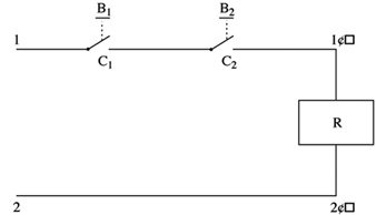
Figure 1 is a diagram of a control circuit requiring two buttons (B1 and B2) to be pressed simultaneously in order to activate the relay coil (R) and start the machine. This example may be used to illustrate, in practical terms, the direct and reverse methods used in system safety analysis.
Figure 1. Two-button control circuit
Direct method
In the direct method, the analyst begins by (1) listing faults, dysfunctions and maladjustments, (2) studying their effects and (3) determining whether or not those effects are a threat to safety. In the case of figure 1, the following faults may occur:
- a break in the wire between 2 and 2´
- unintentional contact at C1 (or C2) as a result of mechanical blocking
- accidental closing of B1 (or B2)
- short circuit between 1 and 1´.
The analyst can then deduce the consequences of these faults, and the findings can be set out in tabular form (table 1).
Table 1. Possible dysfunctions of a two-button control circuit and their consequences
|
Faults |
Consequences |
|
Break in the wire between 2 and 2’ |
Impossible to start the machine* |
|
Accidental closing of B1 (or B2 ) |
No immediate consequence |
|
Contact at C1 (or C2 ) as a result of |
No immediate consequence but possibility of the |
|
Short circuit between 1 and 1’ |
Activation of relay coil R—accidental starting of |
* Occurrence with a direct influence on the reliability of the system
** Occurrence responsible for a serious reduction in the safety level of the system
*** Dangerous occurrence to be avoided
See text and figure 1.
In table 1 consequences which are dangerous or liable to seriously reduce the safety level of the system can be designated by conventional signs such as ***.
Note: In table 1 a break in the wire between 2 and 2´ (shown in figure 1) results in an occurrence that is not considered dangerous. It has no direct effect on the safety of the system; however, the probability of such an incident occurring has a direct bearing on the reliability of the system.
The direct method is particularly appropriate for simulation. Figure 2 shows an analog simulator designed for studying the safety of press-control circuits. The simulation of the control circuit makes it possible to verify that, so long as there is no fault, the circuit is actually capable of ensuring the required function without infringing the safety criteria. In addition, the simulator can allow the analyst to introduce faults in the various components of the circuit, observe their consequences and thus distinguish those circuits that are properly designed (with few or no dangerous faults) from those which are poorly designed. This type of safety analysis may also be performed using a computer.
Figure 2. Simulator for the study of press-control circuits

Reverse method
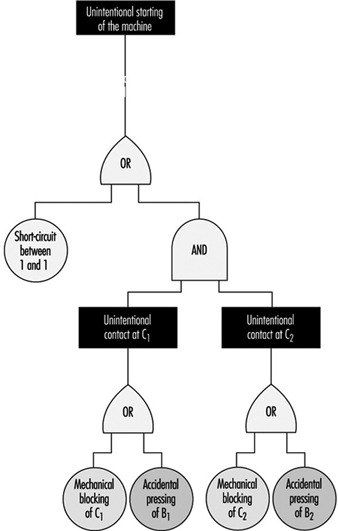
In the reverse method, the analyst works backwards from the undesirable occurrence, incident or accident, towards the various previous events to determine which may be capable of resulting in the occurrences to be avoided. In figure 1, the ultimate occurrence to be avoided would be the unintentional starting of the machine.
- The starting of the machine may be caused by an uncontrolled activation of the relay coil (R).
- The activation of the coil may, in turn, result from a short circuit between 1 and 1´ or from an unintentional and simultaneous closing of switches C1 and C2.
- Unintentional closing of C1 may be the consequence of a mechanical blocking of C1 or of the accidental pressing of B1. Similar reasoning applies to C2.
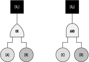
The findings of this analysis can be represented in a diagram which resembles a tree (for this reason the reverse method is known as “fault tree analysis”), such as depicted in figure 3.
Figure 3. Possible chain of events
The diagram follows logical operations, the most important of which are the “OR” and “AND” operations. The “OR” operation signifies that [X1] will occur if either [A] or [B] (or both) take place. The “AND” operation signifies that before [X2] can occur, both [C] and [D] must have taken place (see figure 4).
Figure 4. Representation of two logical operations
The reverse method is very often used in a priori analysis of tangible systems, especially in the chemical, aeronautical, space and nuclear industries. It has also been found extremely useful as a method to investigate industrial accidents.
Although they are very different, the direct and reverse methods are complementary. The direct method is based on a set of faults or dysfunctions, and the value of such an analysis therefore largely depends on the relevance of the various dysfunctions taken into account at the start. Seen in this light, the reverse method seems to be more systematic. Given knowledge of what types of accidents or incidents may happen, the analyst can in theory apply this method to work back towards all the dysfunctions or combinations of dysfunctions capable of bringing them about. However, because all the dangerous behaviours of a system are not necessarily known in advance, they can be discovered by the direct method, applied by simulation, for example. Once these have been discovered, the hazards can be analysed in greater detail by the reverse method.
Problems of System Safety Analysis
The analytical methods described above are not just mechanical processes which need only to be applied automatically in order to reach useful conclusions for improving system safety. On the contrary, analysts encounter a number of problems in the course of their work, and the usefulness of their analyses will depend largely on how they set about solving them. Some of the typical problems that may arise are described below.
Understanding the system to be studied and its operating conditions
The fundamental problems in any system safety analysis are the definition of the system to be studied, its limitations and the conditions under which it is supposed to operate throughout its existence.
If the analyst takes into account a subsystem that is too limited, the result may be the adoption of a series of random preventive measures (a situation in which everything is geared to preventing certain particular types of occurrence, while equally serious hazards are ignored or underestimated). If, on the other hand, the system considered is too comprehensive or general in relation to a given problem, it may result in excessive vagueness of concept and responsibilities, and the analysis may not lead to the adoption of appropriate preventive measures.
A typical example which illustrates the problem of defining the system to be studied is the safety of industrial machines or plant. In this kind of situation, the analyst may be tempted to consider only the actual equipment, overlooking the fact that it has to be operated or controlled by one or more persons. Simplification of this kind is sometimes valid. However, what has to be analysed is not just the machine subsystem but the entire worker-plus-machine system in the various stages of the life of the equipment (including, for example, transport and handling, assembly, testing and adjusting, normal operation, maintenance, disassembly and, in some cases, destruction). At each stage the machine is part of a specific system whose purpose and modes of functioning and malfunctioning are totally different from those of the system at other stages. It must therefore be designed and manufactured in such a way as to permit the performance of the required function under good safety conditions at each of the stages.
More generally, as regards safety studies in firms, there are several system levels: the machine, workstation, shift, department, factory and the firm as a whole. Depending on which system level is being considered, the possible types of dysfunction—and the relevant preventive measures—are quite different. A good prevention policy must make allowance for the dysfunctions that may occur at various levels.
The operating conditions of the system may be defined in terms of the way in which the system is supposed to function, and the environmental conditions to which it may be subject. This definition must be realistic enough to allow for the actual conditions in which the system is likely to operate. A system that is very safe only in a very restricted operating range may not be so safe if the user is unable to keep within the theoretical operating range prescribed. A safe system must thus be robust enough to withstand reasonable variations in the conditions in which it functions, and must tolerate certain simple but foreseeable errors on the part of the operators.
System modelling
It is often necessary to develop a model in order to analyse the safety of a system. This may raise certain problems which are worth examining.
For a concise and relatively simple system such as a conventional machine, the model is almost directly derivable from the descriptions of the material components and their functions (motors, transmission, etc.) and the way in which these components are interrelated. The number of possible component failure modes is similarly limited.
Modern machines such as computers and robots, which contain complex components like microprocessors and electronic circuits with very large-scale integration, pose a special problem. This problem has not been fully resolved in terms either of modelling or of predicting the different possible failure modes, because there are so many elementary transistors in each chip and because of the use of diverse kinds of software.
When the system to be analysed is a human organization, an interesting problem encountered in modelling lies in the choice and definition of certain non-material or not fully material components. A particular workstation may be represented, for example, by a system comprising workers, software, tasks, machines, materials and environment. (The “task” component may prove difficult to define, for it is not the prescribed task that counts but the task as it is actually performed).
When modelling human organizations, the analyst may opt to break down the system under consideration into an information subsystem and one or more action subsystems. Analysis of failures at different stages of the information subsystem (information acquisition, transmission, processing and use) can be highly instructive.
Problems associated with multiple levels of analysis
Problems associated with multiple levels of analysis often develop because starting from an unwanted occurrence, the analyst may work back towards incidents that are more and more remote in time. Depending on the level of analysis considered, the nature of the dysfunctions that occur varies; the same applies to the preventive measures. It is important to be able to decide at what level analysis should be stopped and at what level preventive action should be taken. An example is the simple case of an accident resulting from a mechanical failure caused by the repeated utilization of a machine under abnormal conditions. This may have been caused by a lack of operator training or from poor organization of work. Depending on the level of analysis considered, the preventive action required may be the replacement of the machine by another machine capable of withstanding more severe conditions of use, the use of the machine only under normal conditions, changes in personnel training, or a reorganization of work.
The effectiveness and scope of a preventive measure depend on the level at which it is introduced. Preventive action in the immediate vicinity of the unwanted occurrence is more likely to have a direct and rapid impact, but its effects may be limited; on the other hand, by working backwards to a reasonable extent in the analysis of events, it should be possible to find types of dysfunction that are common to numerous accidents. Any preventive action taken at this level will be much wider in scope, but its effectiveness may be less direct.
Bearing in mind that there are several levels of analysis, there may also be numerous patterns of preventive action, each of which carries its own share of the work of prevention. This is an extremely important point, and one need only return to the example of the accident presently under consideration to appreciate the fact. Proposing that the machine be replaced by another machine capable of withstanding more severe conditions of use places the onus of prevention on the machine. Deciding that the machine should be used only under normal conditions means placing the onus on the user. In the same way, the onus may be placed on personnel training, organization of work or simultaneously on the machine, the user, the training function and the organization function.
For any given level of analysis, an accident often appears to be the consequence of the combination of several dysfunctions or maladjustments. Depending on whether action is taken on one dysfunction or another, or on several simultaneously, the pattern of preventive action adopted will vary.
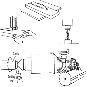
Hand and Portable Power Tool Safety
Tools are such a common part of our lives that it is sometimes difficult to remember that they may pose hazards. All tools are manufactured with safety in mind, but occasionally an accident may occur before tool-related hazards are recognized. Workers must learn to recognize the hazards associated with the different types of tools and the safety precautions required to prevent those hazards. Appropriate personal protective equipment, such as safety goggles or gloves, should be worn for protection from potential hazards that may be encountered while using portable power tools and hand tools.
Hand Tools
Hand tools are non-powered and include everything from axes to wrenches. The greatest hazards posed by hand tools result from misuse, use of the wrong tool for the job, and improper maintenance. Some of the hazards associated with the use of hand tools include but are not limited to the following:
- Using a screwdriver as a chisel may cause the tip of the screwdriver to break off and fly, hitting the user or other employees.
- If a wooden handle on a tool such as a hammer or an axe is loose, splintered or cracked, the head of the tool may fly off and strike the user or another worker.
- A wrench must not be used if its jaws are sprung, because it might slip.
- Impact tools such as chisels, wedges or drift pins are unsafe if they have mushroomed heads which might shatter on impact, sending sharp fragments flying.
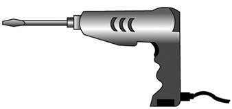
The employer is responsible for the safe condition of tools and equipment provided to employees, but the employees have the responsibility to use and maintain the tools properly. Workers should direct saw blades, knives or other tools away from aisle areas and other employees working in close proximity. Knives and scissors must be kept sharp, as dull tools can be more hazardous than sharp ones. (See figure 1.)
Figure 1. A screwdriver

Safety requires that floors be kept as clean and dry as possible to prevent accidental slips when working with or around dangerous hand tools. Although sparks produced by iron and steel hand tools are not normally hot enough to be sources of ignition, when working with or around flammable materials, spark-resistant tools made from brass, plastic, aluminium or wood may be used to prevent spark formation.
Power Tools
Power tools are hazardous when improperly used. There are several types of power tools, usually categorized according to the power source (electric, pneumatic, liquid fuel, hydraulic, steam and explosive powder actuated). Employees should be qualified or trained in the use of all power tools used in their work. They should understand the potential hazards associated with the use of power tools, and observe the following general safety precautions to prevent those hazards from occurring:
- Never carry a tool by the cord or hose.
- Never yank the cord or the hose to disconnect it from the receptacle.
- Keep cords and hoses away from heat, oil and sharp edges.
- Disconnect tools when they are not in use, before servicing, and when changing accessories such as blades, bits and cutters.
- All observers should stay a safe distance away from the work area.
- Secure work with clamps or a vise, freeing both hands to operate the tool.
- Avoid accidental starting. The worker should not hold a finger on the switch button while carrying a plugged-in tool. Tools which have lock-on controls should be disengaged when power is interrupted so that they do not start up automatically upon restoration of power.
- Tools should be maintained with care and kept sharp and clean for best performance. Instructions in the user’s manual should be followed for lubrication and changing accessories.
- Workers should assure they have good footing and balance when using power tools. Appropriate apparel should be worn, as loose clothing, ties or jewellery can become caught in moving parts.
- All portable electric tools that are damaged shall be removed from use and tagged “Do Not Use” to prevent electrical shock.
Protective Guards
Hazardous moving parts of power tools need to be safeguarded. For example, belts, gears, shafts, pulleys, sprockets, spindles, drums, flywheels, chains or other reciprocating, rotating or moving parts of equipment must be guarded if such parts are exposed to contact by workers. Where necessary, guards should be provided to protect the operator and others with respect to hazards associated with:
- the point of operation
- in-running nip points
- rotating and reciprocating parts
- flying chips and sparks, and mist or spray from metal-working fluids.
Safety guards must never be removed when a tool is being used. For example, portable circular saws must be equipped with guards. An upper guard must cover the entire blade of the saw. A retractable lower guard must cover the teeth of the saw, except when it makes contact with the work material. The lower guard must automatically return to the covering position when the tool is withdrawn from the work. Note the blade guards in the illustration of a power saw (figure 2).
Figure 2. A circular saw with guard
Safety Switches and Controls
The following are examples of hand-held power tools which must be equipped with a momentary contact “on-off” control switch:
- drills, tappers and fastener drivers
- horizontal, vertical and angle grinders with wheels larger than 2 inches (5.1 cm) in diameter
- disc and belt sanders
- reciprocating and sabre saws.
These tools also may be equipped with a lock-on control, provided that turnoff can be accomplished by a single motion of the same finger or fingers that turn it on.
The following hand-held power tools may be equipped with only a positive “on-off” control switch:
- platen sanders
- disc sanders with discs 2 inches (5.1 cm) or less in diameter
- grinders with wheels 2 inches (5.1 cm) or less in diameter
- routers and planers
- laminate trimmers, nibblers and shears
- scroll saws and jigsaws with blade shanks ¼ inch (0.64 cm) wide or less.
Other hand-held power tools which must be equipped with a constant pressure switch that will shut off the power when the pressure is released include:
- circular saws having a blade diameter greater than 2 inches (5.1 cm)
- chain-saws
- percussion tools without positive accessory-holding means.
Electric Tools
Workers using electric tools must be aware of several dangers. The most serious of these is the possibility of electrocution, followed by burns and slight shocks. Under certain conditions, even a small amount of current can result in fibrillation of the heart which may result in death. A shock also may cause a worker to fall off a ladder or other elevated work surfaces.
To reduce the potential of injury to workers from shock, tools must be protected by at least one of the following means:
- Grounded by a three-wire cord (with a ground wire). Three-wire cords contain two current-carrying conductors and a grounding conductor. One end of the grounding conductor connects to the tool’s metal housing. The other end is grounded through a prong on the plug. Any time an adapter is used to accommodate a two-hole receptacle, the adapter wire must be attached to a known ground. The third prong should never be removed from the plug. (See figure 3.)
- Double insulated. The worker and the tools are protected in two ways: (1) by normal insulation on the wires inside, and (2) by a housing that cannot conduct electricity to the operator in the event of a malfunction.
- Powered by a low-voltage isolation transformer.
- Connected through ground fault circuit interrupters. These are permanent and portable devices which instantaneously disconnect a circuit when it seeks ground through a worker’s body or through grounded objects.
These general safety practices should be followed in using electric tools:
- Electric tools should be operated within their design limitations.
- Gloves and safety footwear are recommended during use of electric tools.
- When not in use, tools should be stored in a dry place.
- Tools should not be used if wires or connectors are frayed, bent or damaged.
- Electric tools should not be used in damp or wet locations.
- Work areas should be well lighted.
Powered Abrasive Wheels
Powered abrasive grinding, cutting, polishing and wire buffing wheels create special safety problems because the wheels may disintegrate and throw off flying fragments.
Before abrasive wheels are mounted, they should be inspected closely and sound (or ring) tested by tapping gently with a light non-metallic instrument to be sure that they are free from cracks or defects. If wheels are cracked or sound dead, they could fly apart in operation and must not be used. A sound and undamaged wheel will give a clear metallic tone or “ring”.
To prevent the wheel from cracking, the user should be sure it fits freely on the spindle. The spindle nut must be tightened enough to hold the wheel in place without distorting the flange. Follow the manufacturer’s recommendations. Care must be taken to assure that the spindle wheel will not exceed the abrasive wheel specifications. Due to the possibility of a wheel disintegrating (exploding) during start-up, the worker should never stand directly in front of the wheel as it accelerates to full operating speed. Portable grinding tools need to be equipped with safety guards to protect workers not only from the moving wheel surface, but also from flying fragments in case of breakage. In addition, when using a powered grinder, these precautions should be observed:
- Always use eye protection.
- Turn off the power when tool is not in use.
- Never clamp a hand-held grinder in a vise.
Pneumatic Tools
Pneumatic tools are powered by compressed air and include chippers, drills, hammers and sanders. Although there are several potential dangers encountered in the use of pneumatic tools, the main one is the danger of getting hit by one of the tool’s attachments or by some kind of fastener the worker is using with the tool. Eye protection is required and face protection is recommended when working with pneumatic tools. Noise is another hazard. Working with noisy tools such as jackhammers requires proper, effective use of appropriate hearing protection.
When using a pneumatic tool, the worker must check to assure that it is fastened securely to the hose to prevent a disconnection. A short wire or positive locking device attaching the air hose to the tool will serve as an added safeguard. If an air hose is more than½ inch (1.27 cm) in diameter, a safety excess flow valve should be installed at the source of the air supply to shut off the air automatically in case the hose breaks. In general, the same precautions should be taken with an air hose that are recommended for electric cords, because the hose is subject to the same kind of damage or accidental striking, and it also presents a tripping hazard.
Compressed-air guns should never be pointed toward anyone. Workers should never “dead-end” the nozzle against themselves or anyone else. A safety clip or retainer should be installed to prevent attachments, such as a chisel on a chipping hammer, from being unintentionally shot from the barrel. Screens should be set up to protect nearby workers from being struck by flying fragments around chippers, riveting guns, air hammers, staplers or air drills.
Airless spray guns that atomize paints and fluids at high pressures (1,000 pounds or more per square inch) must be equipped with automatic or manual visual safety devices that will prevent activation until the safety device is manually released. Heavy jackhammers can cause fatigue and strains which may be reduced by the use of heavy rubber grips that provide a secure handhold. A worker operating a jackhammer must wear safety glasses and safety shoes to protect against injury if the hammer slips or falls. A face shield also should be used.
Fuel-Powered Tools
Fuel-powered tools are usually operated using small gasoline-powered internal combustion motors. The most serious potential dangers associated with the use of fuel-powered tools comes from hazardous fuel vapours that can burn or explode and give off dangerous exhaust fumes. The worker must be careful to handle, transport and store the gasoline or fuel only in approved flammable liquid containers, according to proper procedures for flammable liquids. Before the tank for a fuel-powered tool is refilled, the user must shut down the engine and allow it to cool to prevent accidental ignition of hazardous vapours. If a fuel-powered tool is used inside a closed area, effective ventilation and/or protective equipment is necessary to prevent exposure to carbon monoxide. Fire extinguishers must be available in the area.
Explosive Powder-Actuated Tools
Explosive powder-actuated tools operate like a loaded gun and should be treated with the same respect and precautions. In fact, they are so dangerous that they must be operated only by specially trained or qualified employees. Suitable ear, eye and face protection are essential when using a powder-actuated tool. All powder-actuated tools should be designed for varying powder charges so that the user can select a powder level necessary to do the work without excessive force.
The muzzle end of the tool should have a protective shield or guard centred perpendicularly on the barrel to protect the user from any flying fragments or particles that might create a hazard when the tool is fired. The tool must be designed so that it will not fire unless it has this kind of safety device. To prevent the tool from firing accidentally, two separate motions are required for firing: one to bring the tool into position, and another to pull the trigger. The tools must not be able to operate until they are pressed against the work surface with a force at least 5 pounds greater than the total weight of the tool.
If a powder-actuated tool misfires, the user should wait at least 30 seconds before trying to fire it again. If it still will not fire, the user should wait at least another 30 seconds so that the faulty cartridge is less likely to explode, then carefully remove the load. The bad cartridge should be put in water or otherwise safely disposed of in accordance with employer’s procedures.
If a powder-actuated tool develops a defect during use, it should be tagged and taken out of service immediately until it is properly repaired. Precautions for the safe use and handling of powder-actuated tools include the following:
- Powder-actuated tools should not be used in explosive or flammable atmospheres except upon issuance of a hot-work permit by an authorized person.
- Before using the tool, the worker should inspect it to determine that it is clean, that all moving parts operate freely and that the barrel is free from obstructions.
- The tool should never be pointed at anybody.
- The tool should not be loaded unless it is to be used immediately. A loaded tool should not be left unattended, especially where it may be available to unauthorized persons.
- Hands should be kept clear of the barrel end.
In using powder-actuated tools to apply fasteners, the following safety precautions should be considered:
- Do not fire fasteners into material that would let them pass through to the other side.
- Do not drive fasteners into materials like brick or concrete any closer than 3 inches (7.6 cm) to an edge or corner, or into steel any closer than ½ inch (1.27 cm) to a corner or edge.
- Do not drive fasteners into very hard or brittle material that might chip, shatter or make the fasteners ricochet.
- Use an alignment guide when shooting fasteners into existing holes. Do not drive fasteners into a spalled area caused by an unsatisfactory fastening.
Hydraulic Power Tools
The fluid used in hydraulic power tools must be approved for the expected use and must retain its operating characteristics at the most extreme temperatures to which it will be exposed. The manufacturer’s recommended safe operating pressure for hoses, valves, pipes, filters and other fittings must not be exceeded. Where there is a potential for a leak under high pressure in an area where sources of ignition, such as open flames or hot surfaces, may be present, the use of fire-resistant fluids as the hydraulic medium should be considered.
Jacks
All jacks—lever and ratchet jacks, screw jacks and hydraulic jacks—must have a device that stops them from jacking up too high. The manufacturer’s load limit must be permanently marked in a prominent place on the jack and should not be exceeded. Use wooden blocking under the base if necessary to make the jack level and secure. If the lift surface is metal, place a 1-inch-thick (2.54 cm) hardwood block or equivalent between the underside of the surface and the metal jack head to reduce the danger of slippage. A jack should never be used to support a lifted load. Once the load has been lifted, it should immediately be supported by blocks.
To set up a jack, make certain of the following conditions:
- The base rests on a firm level surface.
- The jack is correctly centred.
- The jack head bears against a level surface.
- The lift force is applied evenly.
Proper maintenance of jacks is essential for safety. All jacks must be inspected before each use and lubricated regularly. If a jack is subjected to an abnormal load or shock, it should be thoroughly examined to make sure it has not been damaged. Hydraulic jacks exposed to freezing temperatures must be filled with an adequate antifreeze liquid.
Summary
Workers who use hand and power tools and who are exposed to the hazards of falling, flying, abrasive and splashing objects and materials, or to hazards of harmful dusts, fumes, mists, vapours or gases, must be provided with the appropriate personal equipment necessary to protect them from the hazard. All hazards involved in the use of power tools can be prevented by workers following five basic safety rules:
- Keep all tools in good condition with regular maintenance.
- Use the right tool for the job.
- Examine each tool for damage before use.
- Operate tools according to the manufacturer’s instructions.
- Select and use appropriate protective equipment.
Employees and employers have a responsibility to work together to maintain established safe work practices. If a an unsafe tool or hazardous situation is encountered, it should be brought to the attention of the proper individual immediately.
Moving Parts of Machines
This article discusses situations and chains of events leading to accidents attributable to contact with the moving part of machines. People who operate and maintain machinery run the risk of being involved in serious accidents. US statistics suggest that 18,000 amputations and over 800 fatalities in the United States each year are assignable to such causes. According to the US National Institute for Occupational Safety and Health (NIOSH), the “caught in, under, or between” category of injuries in their classification ranked highest among the most important kinds of occupational injuries in 1979. Such injuries generally involved machines (Etherton and Myers 1990). “Contact with moving machine part” has been reported as the principal injury event in just over 10% of occupational accidents ever since this category was introduced into Swedish occupational-injury statistics in 1979.
Most machines have moving parts that can cause injury. Such moving parts may be found at the point of operation where work is performed on the material, such as where cutting, shaping, boring or deforming takes place. They may be found in the apparatus which transmits energy to the parts of the machine carrying out the work, such as flywheels, pulleys, connecting rods, couplers, cams, spindles, chains, cranks and gears. They may be found in other moving parts of the machine such as wheels on mobile equipment, gear motors, pumps, compressors and so forth. Hazardous machine movements can also be found among other sorts of machinery, especially in the auxiliary pieces of equipment which handle and transport such loads as work pieces, materials, waste or tools.
All parts of a machine that move in the course of the performance of work may contribute to accidents causing injury and damages. Both rotating and linear machine movements, as well as their sources of power, can be dangerous:
Rotating motion. Even smooth rotating shafts can grip an item of clothing and, for example, draw a person’s arm into a hazardous position. The danger in a rotating shaft increases if it has projecting parts or uneven or sharp surfaces, such as adjusting screws, bolts, slits, notches or cutting edges. Rotating machine parts give rise to “nip points” in three different ways:
- There are the points between two rotating parts that rotate in opposite directions and have parallel axes, such as gears or cog-wheels, carriage rollers or mangles.
- There are the points of contact between rotating parts and parts in linear movement, such as found between a power-transmission belt and its pulley, a chain and a sprocket, or a rack and pinion.
- Rotating machine movements can give rise to the risk of cuts and crushing injuries when they take place in close proximity to stationary objects—this sort of condition exists between a worm conveyor and its housing, between the spokes of a wheel and the machine bed, or between a grinding wheel and a tool jig.
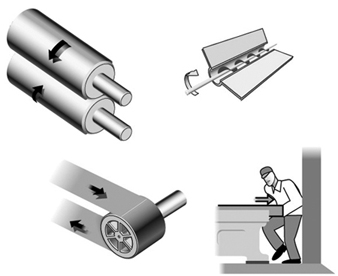
Linear movements. Vertical, horizontal and reciprocating motion can cause injury in several ways: a person may receive a shove or blow from a machine part, and may be caught between the machine part and some other object, or may be cut by a sharp edge, or sustain a nip injury by being trapped between the moving part and another object (figure 1).
Figure 1. Examples of mechanical movements that can injure a person
Power sources. Frequently, external sources of power are employed to run a machine which may involve considerable quantities of energy. These include electric, steam, hydraulic, pneumatic and mechanical power systems, all of which, if released or uncontrolled, can give rise to serious injuries or damage. A study of accidents that occurred over one year (1987 to 1988) among farmers in nine villages in northern India showed that fodder-cutting machines, all otherwise of the same design, are more dangerous when powered by a motor or tractor. The relative frequency of accidents involving more than a minor injury (per machine) was 5.1 per thousand for manual cutters and 8.6 per thousand for powered cutters (Mohan and Patel 1992).
Injuries Associated with Machine Movements
Since the forces associated with machine movements are often quite large, it can be presumed that the injuries to which they give rise will be serious. This presumption is confirmed by several sources. “Contact with moving machinery or material being machined” accounted for only 5% of all occupational accidents but for as much as 10% of fatal and major accidents (fractures, amputations and so on) according to British statistics (HSE 1989). Studies of two vehicle-manufacturing workplaces in Sweden point in the same direction. Accidents caused by machine movements gave rise to twice the number of days of sick leave, as measured by median values, compared to non-machine-related accidents. Machine-related accidents also differed from other accidents with regard to part of the body injured: The results indicated that 80% of the injuries sustained in “machine” accidents were to the hands and fingers, while the corresponding proportion for “other” accidents was 40% (Backström and Döös 1995).
The risk situation at automated installations has turned out to be both different (in terms of type of accident, sequence of events and degree of injury severity) and more complicated (both in technical terms and with regard to the need for specialized skills) than at installations where conventional machinery is used. The term automated is herein meant to refer to equipment which, without the direct intervention of a human being, can either initiate a machine movement or change its direction or function. Such equipment requires sensor devices (e.g., position sensors or microswitches) and/or some form of sequential controls (e.g., a computer program) to direct and monitor their activities. Over recent decades, a programmable logic controller (PLC) has been increasingly employed as the control unit in production systems. Small computers are now the most common means used for controlling production equipment in the industrialized world, while other means of control, such as electro-mechanical units, are becoming less and less common. In the Swedish manufacturing industry, the use of numerically controlled (NC) machines increased by 11 to 12% per year over the 1980s (Hörte and Lindberg 1989). In modern industrial production, being injured by “moving parts of machines” is increasingly becoming equivalent to being injured by “computer-controlled machine movements”.
Automated installations are found in more and more sectors of industry, and they have an increasing number of functions. Stores management, materials handling, processing, assembly and packaging are all being automated. Series production has come to resemble process production. If the feeding, machining and ejection of work pieces are mechanized, the operator no longer needs to be in the risk zone during the course of regular, undisturbed production. Research studies of automated manufacturing have shown that accidents occur primarily in the handling of disturbances affecting production. However, people can also get in the way of machine movements in performing other tasks, such as cleaning, adjusting, resetting, controlling and repairing.
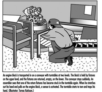
When production is automated and the process is no longer under the direct control of the human being, the risk of unexpected machine movements increases. Most operators who work with groups or lines of inter-linked machines have experienced such unexpected machine movements. Many automation accidents occur as a result of just such movements. An automation accident is an accident in which the automatic equipment controlled (or should have controlled) the energy giving rise to the injury. This means that the force which injures the person comes from the machine itself (e.g., the energy of a machine movement). In a study of 177 automation accidents in Sweden, it was found that injury was caused by the “unexpected start” of a part of a machine in 84% of cases (Backström and Harms-Ringdahl 1984). A typical example of an injury caused by a computer-controlled machine movement is shown in figure 2.
Figure 2. A typical example of an injury caused by a computer-controlled machine movement
One of the studies referred to above (Backström and Döös 1995) showed that automatically controlled machine movements were causally linked to longer periods of sick leave than injuries due to other kinds of machine movements, the median value being four times higher at one of the workplaces. The injury pattern of automation accidents was similar to that for other machine accidents (mainly involving hands and fingers), but the tendency was for the former kind of injuries to be more serious (amputations, crushes and fractures).
Computer control, like manual, has weaknesses from the perspective of reliability. There is no guarantee that a computer program will operate without error. The electronics, with their low signal levels, may be sensitive to interference if not properly protected, and the consequences of resultant failures are not always possible to predict. Furthermore, programming changes are often left undocumented. One method used to compensate for this weakness is, for example, by operating “double” systems in which there are two independent chains of functional components and a method for monitoring such that both chains display the same value. If the systems display different values, this indicates a failure in one of them. But there is a possibility that both chains of components may suffer from the same fault and that they both can be put out of order by the same disturbance, thereby giving a false positive reading (as both systems agree). However, in only a few of the cases investigated has it been possible to trace an accident to computer failure (see below), despite the fact that it is common for a single computer to control all the functions of an installation (even the stopping of a machine as a result of the activation of a safety device). As an alternate, consideration may be given to providing a tried-and-tested system with electro-mechanical components for safety functions.
Technical Problems
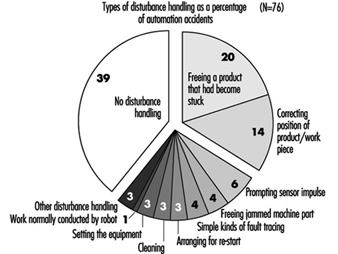
In general, it can be said that a single accident has many causes, including technical, individual, environmental and organizational ones. For preventive purposes, an accident is best looked at not as an isolated event, but as a sequence of events or a process (Backström 1996). In the case of automation accidents, it has been shown that technical problems are frequently part of such a sequence and occur either at one of the early stages of the process or close to the injury event of the accident. Studies in which technical problems involved in automation accidents have been examined suggest that these lie behind 75 to 85% of the accidents. At the same time, in any specific case, there are usually other causes, such as those of an organizational nature. Only in one-tenth of cases has it been found that the direct source of the energy giving rise to an injury could be attributed to technical failure—for example, a machine movement taking place despite the machine’s being in the stop position. Similar figures have been reported in other studies. Usually, a technical problem led to trouble with the equipment, so that the operator had to switch tasks (e.g., to re-position a part that was in a crooked position). The accident then occurred during the implementation of the task, prompted by the technical failure. A quarter of the automation accidents were preceded by a disturbance in the materials flow such as a part becoming stuck or getting into a crooked or otherwise faulty position (see figure 3).
Figure 3. Types of technical problems involved in automation accidents (number of accidents =127)
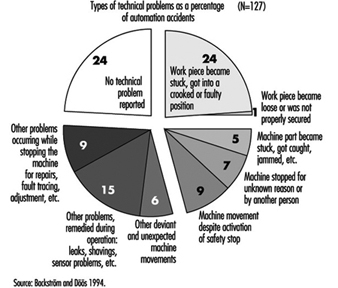
In a study of 127 accidents involving automation, 28 of these accidents, described in figure 4, were further investigated to determine the types of technical problems which were involved as causal factors (Backström and Döös, in press). The problems specified in the accident investigations were most frequently caused by jammed, defective or worn-out components. In two cases, a problem was caused by a computer-program error, and in one by electromagnetic interference. In more than half of the cases (17 out of 28), faults had been present for some time but not remedied. Only in 5 of the 28 cases where a technical failure or deviation was referred to, had the defect not manifested itself previously. Some faults had been repaired only to reappear later. Certain defects had been present right from the time of installation, while others resulted from wear and the impact of the environment.
The proportion of automation accidents occurring in the course of the correction of a disturbance to production comes to between one-third and two-thirds of all cases, according to most studies. In other words, there is general agreement that handling production disturbances is a hazardous occupational task. The variation in the extent to which such accidents occur has many explanations, among them those related to the type of production and to how occupational tasks are classified. In some studies of disturbances, only problems and machine stops in the course of regular production have been considered; in others, a wider range of problems have been treated—for example, those involved in the setting up of work.
A very important measure in the prevention of automation accidents is to prepare procedures for removing the causes of production disturbances so that they are not repeated. In a specialized study of production disturbances at time of accident (Döös and Backström 1994), it was found that the most common task to which disturbances gave rise was the freeing or the correcting of the position of a work piece that had become stuck or wrongly placed. This type of problem initiated one of two rather similar sequences of events: (1) the part was freed and came into its correct position, the machine received an automatic signal to start, and the person was injured by the machine movement initiated, (2) there was not time for the part to be freed or repositioned before the person was injured by a machine movement that came unexpectedly, more quickly or was of greater force than the operator expected. Other disturbance-handling involved prompting a sensor impulse, freeing a jammed machine part, carrying out simple kinds of fault tracing, and arranging for restart (see figure 4).
Figure 4. Type of disturbance handling at time of accident (number of accidents =76)
Worker Safety
The categories of personnel which tend to be injured in automation accidents depend on how work is organized—that is, on which occupational group performs the hazardous tasks. In practice, this is a matter of which person at the workplace is assigned to deal with problems and disturbances on a routine basis. In modern Swedish industry, active interventions are usually demanded from the persons operating the machine. This is why, in the previously mentioned vehicle-manufacturing workplace study in Sweden (Backström and Döös, accepted for publication), it was found that 82% of the people who sustained injuries from automated machines were production workers or operators. Operators also had a higher relative accident frequency (15 automation accidents per 1,000 operators per year) than maintenance workers (6 per 1,000). The findings of studies which indicate that maintenance workers are more affected are at least partly to be explained by the fact that operators are not allowed to enter machining areas in some companies. In organizations with a different type of task distribution, other categories of personnel—setters, for example—may be given the task of solving any production problems that arise.
The most common corrective measure taken in this connection in order to raise the level of personal safety is to protect the person from hazardous machine movements by using some kind of safety device, such as machine guarding. The main principle here is that of “passive” safety—that is, the provision of protection that does not require action on the part of the worker. It is, however, impossible to judge the effectiveness of protective devices without very good acquaintance with the actual work requirements at the machine in question, a form of knowledge which is normally possessed only by machine operators themselves.
There are many factors that can put even what is apparently good machine protection out of action. In order to perform their work, operators may need to disengage or circumvent a safety device. In one study (Döös and Backström 1993), it was found that such disengagement or circumvention had taken place in 12 out of 75 of the automation accidents covered. It is often a matter of the operator’s being ambitious, and no longer willing to accept either production problems or the delay to the production process involved in correcting disturbances in accordance with instructions. One way of avoiding this problem is to make the protective device imperceptible, so that it does not affect the pace of production, product quality or task performance. But this is not always possible; and where there are repeated disturbances to production, even minor inconveniences can prompt people not to utilize safety devices. Again, routines should be made available to remove the causes of production disturbances so that these are not repeated. A lack of a means of confirming that safety devices really function according to specifications is a further significant risk factor. Faulty connections, start signals that remain in the system and later give rise to unexpected starts, build-up in air pressure, and sensors that have come loose may all cause failure of protective equipment.
Summary
As has been shown, technical solutions to problems may give rise to new problems. Although injuries are caused by machine movements, which are essentially technical by nature, this does not automatically mean that the potential for their eradication lies in purely technical factors. Technical systems will continue to malfunction, and people will fail to handle the situations to which these malfunctions give rise. The risks will continue to exist, and can be held in check only by a wide variety of means. Legislation and control, organizational measures at individual companies (in the form of training, safety rounds, risk analysis and the reporting of disturbances and near accidents), and an emphasis on steady, ongoing improvements are all needed as complements to purely technical development.
Machine Safeguarding
There seem to be as many potential hazards created by moving machine parts as there are different types of machines. Safeguards are essential to protect workers from needless and preventable machinery-related injuries. Therefore, any machine part, function or process which may cause injury should be safeguarded. Where the operation of a machine or accidental contact with it can injure the operator or others in the vicinity, the hazard must be either controlled or eliminated.
Mechanical Motions and Actions
Mechanical hazards typically involve dangerous moving parts in the following three basic areas:
- the point of operation, that point where work is performed on the material, such as cutting, shaping, punching, stamping, boring or forming of stock
- power transmission apparatus, any components of the mechanical system which transmit energy to the parts of the machine performing the work. These components include flywheels, pulleys, belts, connecting rods, couplings, cams, spindles, chains, cranks and gears
- other moving parts, all parts of the machine which move while the machine is working, such as reciprocating, rotating and transversely moving parts, as well as feed mechanisms and auxiliary parts of the machine.
A wide variety of mechanical motions and actions which may present hazards to workers include the movement of rotating members, reciprocating arms, moving belts, meshing gears, cutting teeth and any parts that impact or shear. These different types of mechanical motions and actions are basic to nearly all machines, and recognizing them is the first step toward protecting workers from the hazards they may present.
Motions
There are three basic types of motion: rotating, reciprocating and transverse.
Rotating motion can be dangerous; even smooth, slowly rotating shafts can grip clothing and force an arm or hand into a dangerous position. Injuries due to contact with rotating parts can be severe (see figure 1).
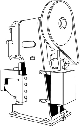
Figure 1. Mechanical punch press
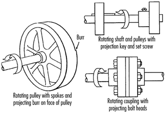
Collars, couplings, cams, clutches, flywheels, shaft ends, spindles and horizontal or vertical shafting are some examples of common rotating mechanisms which may be hazardous. There is added danger when bolts, nicks, abrasions and projecting keys or set screws are exposed on rotating parts on machinery, as shown in figure 2.
Figure 2. Examples of hazardous projections on rotating parts
In-running nip points are created by rotating parts on machinery. There are three main types of in-running nip points:
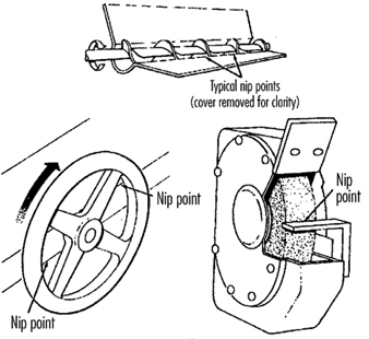
- Parts with parallel axes can rotate in opposite directions. These parts may be in contact (thereby producing a nip point) or in close proximity to each other, in which case the stock fed between the rolls produces the nip points. This danger is common on machinery with intermeshing gears, rolling mills and calenders, as shown in figure 3.
- Another type of nip point is created between rotating and tangentially moving parts, such as the point of contact between a power transmission belt and its pulley, a chain and a sprocket, or a rack and pinion, as shown in figure 4.
- Nip points can also occur between rotating and fixed parts which create a shearing, crushing or abrading action. Examples include handwheels or flywheels with spokes, screw conveyors or the periphery of an abrasive wheel and an incorrectly adjusted work rest, as shown in figure 5.
Figure 3. Common nip points on rotating parts
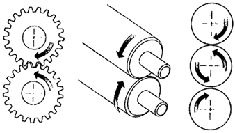
Figure 4. Nip points between rotating elements and parts with longitudinal motions
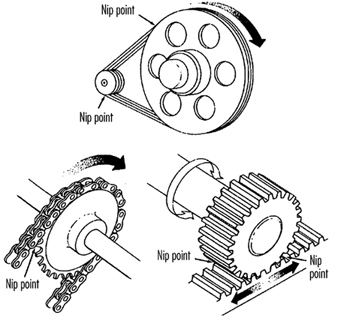
Figure 5. Nip points between rotating machine components
Reciprocating motions may be hazardous because during the back-and-forth or up-and-down motion, a worker may be struck by or caught between a moving part and a stationary part. An example is shown in figure 6.
Figure 6. Hazardous reciprocating motion
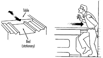
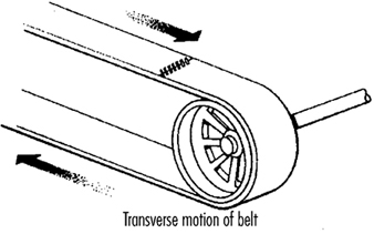
Transverse motion (movement in a straight, continuous line) creates a hazard because a worker may be struck or caught in a pinch or shear point by a moving part. An example of transverse motion is shown in figure 7.
Figure 7. Example of transverse motion
Actions
There are four basic types of action: cutting, punching, shearing and bending.
Cutting action involves rotating, reciprocating or transverse motion. Cutting action creates hazards at the point of operation where finger, head and arm injuries can occur and where flying chips or scrap material can strike the eyes or face. Typical examples of machines with cutting hazards include band saws, circular saws, boring or drilling machines, turning machines (lathes) and milling machines. (See figure 8.)
Figure 8. Examples of cutting hazards
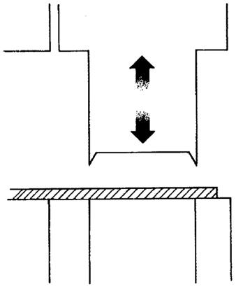
Punching action results when power is applied to a slide (ram) for the purpose of blanking, drawing or stamping metal or other materials. The danger of this type of action occurs at the point of operation where stock is inserted, held and withdrawn by hand. Typical machines which use punching action are power presses and iron workers. (See figure 9.)
Figure 9. Typical punching operation
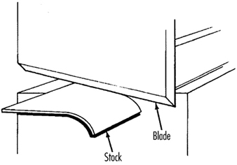
Shearing action involves applying power to a slide or knife in order to trim or shear metal or other materials. A hazard occurs at the point of operation where stock is actually inserted, held and withdrawn. Typical examples of machinery used for shearing operations are mechanically, hydraulically or pneumatically powered shears. (See figure 10.)
Figure 10. Shearing operation
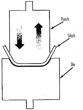
Bending action results when power is applied to a slide in order to shape, draw or stamp metal or other materials. The hazard occurs at the point of operation where stock is inserted, held and withdrawn. Equipment that uses bending action includes power presses, press brakes and tubing benders. (See figure 11.)
Figure 11. Bending operation
Requirements for Safeguards
Safeguards must meet the following minimum general requirements to protect workers against mechanical hazards:
Prevent contact. The safeguard must prevent hands, arms or any part of a worker’s body or clothing from making contact with dangerous moving parts by eliminating the possibility of the operators or other workers placing parts of their bodies near hazardous moving parts.
Provide security. Workers should not be able to easily remove or tamper with the safeguard. Guards and safety devices should be made of durable material that will withstand the conditions of normal use and that are firmly secured to the machine.
Protect from falling objects. The safeguard should ensure that no objects can fall into moving parts and damage the equipment or become a projectile that could strike and injure someone.
Not create new hazards. A safeguard defeats its purpose if it creates a hazard of its own, such as a shear point, a jagged edge or an unfinished surface. The edges of guards, for example, should be rolled or bolted in such a way that they eliminate sharp edges.
Not create interference. Safeguards which impede workers from performing their jobs might soon be overridden or disregarded. If possible, workers should be able to lubricate machines without disengaging or removing safeguards. For example, locating oil reservoirs outside the guard, with a line leading to the lubrication point, will reduce the need to enter the hazardous area.
Safeguard Training
Even the most elaborate safeguarding system cannot offer effective protection unless workers know how to use it and why. Specific and detailed training is an important part of any effort to implement safeguarding against machine-related hazards. Proper safeguarding may improve productivity and enhance efficiency since it may relieve workers’ apprehensions about injury. Safeguard training is necessary for new operators and maintenance or set-up personnel, when any new or altered safeguards are put in service, or when workers are assigned to a new machine or operation; it should involve instruction or hands-on training in the following:
- a description and identification of the hazards associated with particular machines and the specific safeguards against each hazard
- how the safeguards provide protection; how to use the safeguards and why
- how and under what circumstances safeguards can be removed, and by whom (in most cases, repair or maintenance personnel only)
- what to do (e.g., contact the supervisor) if a safeguard is damaged, missing or unable to provide adequate protection.
Methods of Machine Safeguarding
There are many ways to safeguard machinery. The type of operation, the size or shape of stock, the method of handling, the physical layout of the work area, the type of material and production requirements or limitations will help to determine the appropriate safeguarding method for the individual machine. The machine designer or safety professional must choose the most effective and practical safeguard available.
Safeguards may be categorized under five general classifications: (1) guards, (2) devices, (3) separation, (4) operations and (5) other.
Safeguarding with guards
There are four general types of guards (barriers which prevent access to danger areas), as follows:
Fixed guards. A fixed guard is a permanent part of the machine and is not dependent upon moving parts to perform its intended function. It may be constructed of sheet metal, screen, wire cloth, bars, plastic or any other material that is substantial enough to withstand whatever impact it may receive and to endure prolonged use. Fixed guards are usually preferable to all other types because of their relative simplicity and permanence (see table 1).
Table 1. Machine guards
|
Method |
Safeguarding action |
Advantages |
Limitations |
|
Fixed |
· Provides a barrier |
· Suits many specific applications |
· May interfere with visibility |
|
Interlocked |
· Shuts off or disengages power and prevents starting of machine when guard is open; should require the machine to be stopped before the worker can reach into the danger area |
· Provides maximum protection |
· Requires careful adjustment and maintenance |
|
Adjustable |
· Provides a barrier which may be adjusted to facilitate a variety of production operations |
· Can be constructed to suit many specific applications |
· Operator may enter danger area: protection may not be complete at all times |
|
Self-adjusting |
· Provides a barrier which moves according to the size of the stock entering danger area |
· Off-the-shelf guards are commercially available |
· Does not always provide maximum protection |
In figure 12, a fixed guard on a power press completely encloses the point of operation. The stock is fed through the side of the guard into the die area, with the scrap stock exiting on the opposite side.
Figure 12. Fixed guard on power press
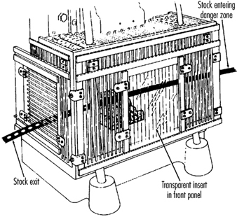
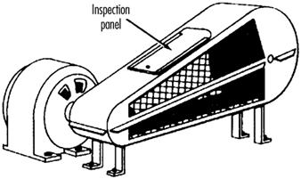
Figure 13 depicts a fixed enclosure guard which shields the belt and pulley of a power transmission unit. An inspection panel is provided on top to minimize the need for removing the guard.
Figure 13. Fixed guard enclosing belts and pulleys
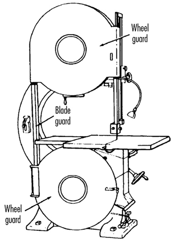
In figure 14, fixed enclosure guards are shown on a bandsaw. These guards protect operators from the turning wheels and moving saw blade. Normally, the only time the guards would be opened or removed would be for a blade change or for maintenance. It is very important that they be securely fastened while the saw is in use.
Figure 14. Fixed guards on band-saw
Interlocked guards. When interlocked guards are opened or removed, the tripping mechanism and/or power automatically shuts off or disengages, and the machine cannot cycle or be started until the interlock guard is back in place. However, replacing the interlock guard should not automatically restart the machine. Interlocked guards may use electrical, mechanical, hydraulic or pneumatic power, or any combination of these. Interlocks should not prevent “inching” (i.e., gradual progressive movements) by remote control, if required.
An example of an interlocking guard is shown in figure 15. In this figure, the beater mechanism of a picker machine (used in the textile industry) is covered by an interlocked barrier guard. This guard cannot be raised while the machine is running, nor can the machine be restarted with the guard in the raised position.
Figure 15. Interlocked guard on picker machine
Adjustable guards. Adjustable guards allow flexibility in accommodating various sizes of stock. Figure 16 shows an adjustable enclosure guard on a band-saw.
Figure 16. Adjustable guard on band-saw
Self-adjusting guards. The openings of self-adjusting guards are determined by the movement of the stock. As the operator moves the stock into the danger area, the guard is pushed away, providing an opening which is large enough to admit only the stock. After the stock is removed, the guard returns to the rest position. This guard protects the operator by placing a barrier between the danger area and the operator. The guards may be constructed of plastic, metal or other substantial material. Self-adjusting guards offer different degrees of protection.
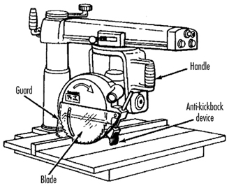
Figure 17 shows a radial-arm saw with a self-adjusting guard. As the blade is pulled across the stock, the guard moves up, staying in contact with the stock.
Figure 17. Self-adjusting guard on radial-arm saw
Safeguarding with devices
Safety devices may stop the machine if a hand or any part of the body is inadvertently placed in the danger area, may restrain or withdraw the operator’s hands from the danger area during operation, may require the operator to use both hands on machine controls simultaneously (thus keeping both hands and body out of danger) or may provide a barrier which is synchronized with the operating cycle of the machine in order to prevent entry to the danger area during the hazardous part of the cycle. There are five basic types of safety devices, as follows:
Presence-sensing devices
Three types of sensing devices which stop the machine or interrupt the work cycle or operation if a worker is within the danger zone are described below:
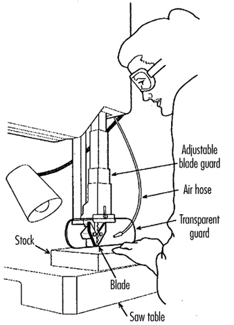
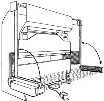
The photoelectric (optical) presence-sensing device uses a system of light sources and controls which can interrupt the machine’s operating cycle. If the light field is broken, the machine stops and will not cycle. This device should be used only on machines which can be stopped before the worker reaches the danger area. Figure 18 shows a photoelectric presence-sensing device used with a press brake. The device may be swung up or down to accommodate different production requirements.
Figure 18. Photoelectric presence-sensing device on press brake
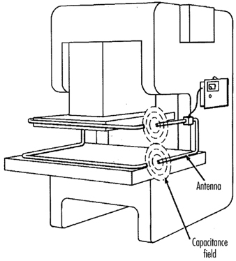
The radio-frequency (capacitance) presence-sensing device uses a radio beam that is part of the control circuit. When the capacitance field is broken, the machine will stop or will not activate. This device should be used only on machines which can be stopped before the worker can reach the danger area. This requires the machine to have a friction clutch or other reliable means for stopping. Figure 19 shows a radio-frequency presence-sensing device mounted on a part-revolution power press.
Figure 19. Radio-frequency presence-sensing device on power saw
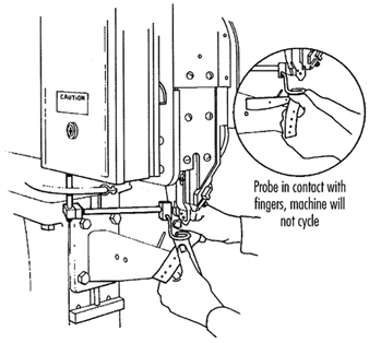
The electro-mechanical sensing device has a probe or contact bar which descends to a predetermined distance when the operator initiates the machine cycle. If there is an obstruction preventing it from descending its full predetermined distance, the control circuit does not actuate the machine cycle. Figure 20 shows an electro-mechanical sensing device on an eyeletter. The sensing probe in contact with the operator’s finger is also shown.
Figure 20. Electromechanical sensing device on eye-letter machine
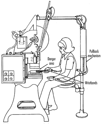
Pullback devices
Pullback devices utilize a series of cables attached to the operator’s hands, wrists and/or arms and are primarily used on machines with stroking action. When the slide/ram is up, the operator is allowed access to the point of operation. When the slide/ram begins to descend, a mechanical linkage automatically assures withdrawal of the hands from the point of operation. Figure 21 shows a pullback device on a small press.
Figure 21. Pullback device on power press
Restraint devices
Restraint devices, which utilize cables or straps that are attached between a fixed point and the operator’s hands, have been used in some countries. These devices are not generally considered to be acceptable safeguards because they are easily bypassed by the operator, thus allowing hands to be placed into the danger zone. (See table 2.)
Table 2. Devices
|
Method |
Safeguarding action |
Advantages |
Limitations |
|
Photoelectric |
· Machine will not start cycling when the light field is interrupted |
· Can allow freer movement for operator |
· Does not protect against mechanical failure |
|
Radio frequency |
· Machine cycling will not start when the capacitance field is interrupted |
· Can allow freer movement for operator |
· Does not protect against mechanical failure |
|
Electro-mechanical |
· Contact bar or probe travels a predetermined distance between the operator and the danger area |
· Can allow access at the point of operation |
· Contact bar or probe must be properly adjusted for each application; this adjustment must be maintained properly |
|
Pullback |
· As the machine begins to cycle, the operator’s hands are pulled out of the danger area |
· Eliminates the need for auxiliary barriers or other interference at the danger area |
· Limits movement of operator |
|
Safety trip controls: |
· Stops machine when tripped |
· Simplicity of use |
· All controls must be manually activated |
|
Two-hand control |
· Concurrent use of both hands is required, preventing the operator from entering the danger area |
· Operator’s hands are at a predetermined location away from danger area |
· Requires a partial cycle machine with a brake |
|
Two-hand trip |
· Concurrent use of two hands on separate controls prevent hands from being in danger area when machine cycle starts |
· Operator’s hands are away from danger area |
· Operator may try to reach into danger area after tripping machine |
|
Gate |
· Provides a barrier between danger area and operator or other personnel |
· Can prevent reaching into or walking into the danger area |
· May require frequent inspection and regular maintenance |
Safety control devices
All of these safety control devices are activated manually and must be manually reset to restart the machine:
- Safety trip controls such as pressure bars, trip rods and tripwires are manual controls which provide a quick means for deactivating the machine in an emergency situation.
- Pressure-sensitive body bars, when depressed, will deactivate the machine if the operator or anyone trips, loses balance or is drawn toward the machine. The positioning of the bar is critical, as it must stop the machine before a part of the body reaches the danger area. Figure 22 shows a pressure-sensitive body bar located on the front of a rubber mill.
Figure 22. Pressure-sensitive body bar on rubber mill

- Safety trip-rod devices deactivate the machine when pressed by hand. Because they have to be actuated by the operator during an emergency situation, their proper position is critical. Figure 23 shows a trip-rod located above the rubber mill.
Figure 23. Safety trip-rod on rubber mill
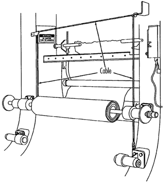
- Safety tripwire cables are located around the perimeter of, or near the danger area. The operator must be able to reach the cable with either hand to stop the machine. Figure 24 shows a calender equipped with this type of control.
Figure 24. Safety tripwire cable on calender
- Two-hand controls require constant, concurrent pressure for the operator to activate the machine. When installed on power presses, these controls use a part-revolution clutch and a brake monitor, as shown in figure 25. With this type of device, the operator’s hands are required to be at a safe location (on control buttons) and at a safe distance from the danger area while the machine completes its closing cycle.
Figure 25. Two-hand control buttons on part-revolution clutch power press

- Two-hand trip. The two-hand trip shown in figure 26 is usually used with machines equipped with full-revolution clutches. It requires concurrent application of both of the operator’s control buttons to activate the machine cycle, after which the hands are free. The trips must be placed far enough from the point of operation to make it impossible for operators to move their hands from the trip buttons or handles into the point of operation before the first half of the cycle is completed. The operator’s hands are kept far enough away to prevent them from being accidentally placed in the danger area before the slide/ram or blade reaches the full down position.
Figure 26. Two-hand control buttons on full-revolution clutch power press
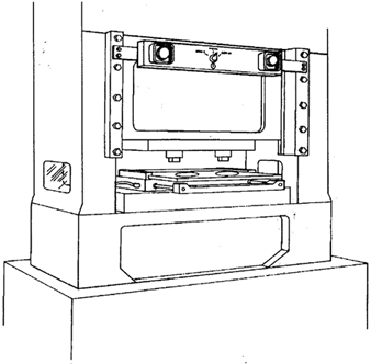
- Gates are safety control devices which provide a movable barrier that protects the operator at the point of operation before the machine cycle can be started. Gates are often designed to be operated with each machine cycle. Figure 27 shows a gate on a power press. If the gate is not permitted to descend to the fully closed position, the press will not function. Another application of gates is their use as a component of a perimeter safeguarding system, where the gates provide protection to the operators and to pedestrian traffic.
Figure 27. Power press with gate
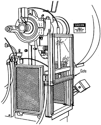
Safeguarding by location or distance
To safeguard a machine by location, the machine or its dangerous moving parts must be so positioned that hazardous areas are not accessible or do not present a hazard to a worker during the normal operation of the machine. This may be accomplished with enclosure walls or fences that restrict access to machines, or by locating a machine so that a plant design feature, such as a wall, protects the worker and other personnel. Another possibility is to have dangerous parts located high enough to be out of the normal reach of any worker. A thorough hazard analysis of each machine and particular situation is essential before attempting this safeguarding technique. The examples mentioned below are a few of the numerous applications of the principle of safeguarding by location/distance.
Feeding process. The feeding process can be safeguarded by location if a safe distance can be maintained to protect the worker’s hands. The dimensions of the stock being worked on may provide adequate safety. For example, when operating a single-end punching machine, if the stock is several feet long and only one end of the stock is being worked on, the operator may be able to hold the opposite end while the work is being performed. However, depending upon the machine, protection might still be required for other personnel.
Positioning controls. The positioning of the operator’s control station provides a potential approach to safeguarding by location. Operator controls may be located at a safe distance from the machine if there is no reason for the operator to be in attendance at the machine.
Feeding and ejection safeguarding methods
Many feeding and ejection methods do not require the operators to place their hands in the danger area. In some cases, no operator involvement is necessary after the machine is set up, whereas in other situations, operators can manually feed the stock with the assistance of a feeding mechanism. Furthermore, ejection methods may be designed which do not require any operator involvement after the machine starts to function. Some feeding and ejection methods may even create hazards themselves, such as a robot which may eliminate the need for an operator to be near the machine but may create a new hazard by the movement of its arm. (See table 3.)
Table 3. Feeding and ejection methods
|
Method |
Safeguarding action |
Advantages |
Limitations |
|
Automatic feed |
· Stock is fed from rolls, indexed by machine mechanism, etc. |
· Eliminates the need for operator involvement in the danger area |
· Other guards are also required for operator protection—usually fixed barrier guards |
|
Semi-automatic |
· Stock is fed by chutes, movable dies, dial |
· Eliminates the need for operator involvement in the danger area |
· Other guards are also required for operator protection—usually fixed barrier guards |
|
Automatic |
· Work pieces are ejected by air or mechanical means |
· Eliminates the need for operator involvement in the danger area |
· May create a hazard of blowing chips or debris |
|
Semi-automatic |
· Work pieces are ejected by mechanical |
· Operater does not have to enter danger area to remove finished work |
· Other guards are required for operator |
|
Robots |
· They perform work usually done by operator |
· Operator does not have to enter danger area |
· Can create hazards themselves |
Using one of the following five feeding and ejection methods to safeguard machines does not eliminate the need for guards and other devices, which must be used as necessary to provide protection from exposure to hazards.
Automatic feed. Automatic feeds reduce the operator exposure during the work process, and often do not require any effort by the operator after the machine is set up and running. The power press in figure 28 has an automatic feeding mechanism with a transparent fixed enclosure guard at the danger area.
Figure 28. Power press with automatic feed
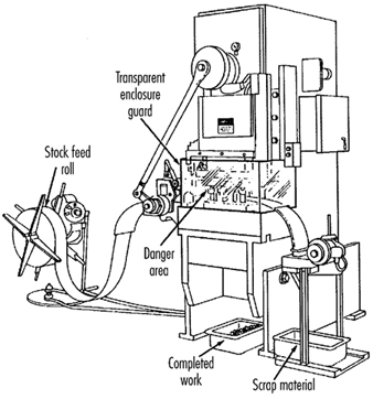
Semi-automatic feed. With semi-automatic feeding, as in the case of a power press, the operator uses a mechanism to place the piece being processed under the ram at each stroke. The operator does not need to reach into the danger area, and the danger area is completely enclosed. Figure 29 shows a chute feed into which each piece is placed by hand. Using a chute feed on an inclined press not only helps centre the piece as it slides into the die, but may also simplify the problem of ejection.
Figure 29. Power press with chute feed
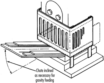
Automatic ejection. Automatic ejection may employ either air pressure or a mechanical apparatus to remove the completed part from a press, and may be interlocked with the operating controls to prevent operation until part ejection is completed. The pan shuttle mechanism shown in figure 30 moves under the finished part as the slide moves toward the up position. The shuttle then catches the part stripped from the slide by the knockout pins and deflects it into a chute. When the ram moves down toward the next blank, the pan shuttle moves away from the die area.
Figure 30. Shuttle ejection system
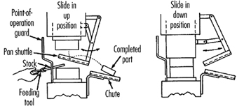
Semi-automatic ejection. Figure 31 shows a semi-automatic ejection mechanism used on a power press. When the plunger is withdrawn from the die area, the ejector leg, which is mechanically coupled to the plunger, kicks the completed work out.
Figure 31. Semi-automatic ejection mechanism
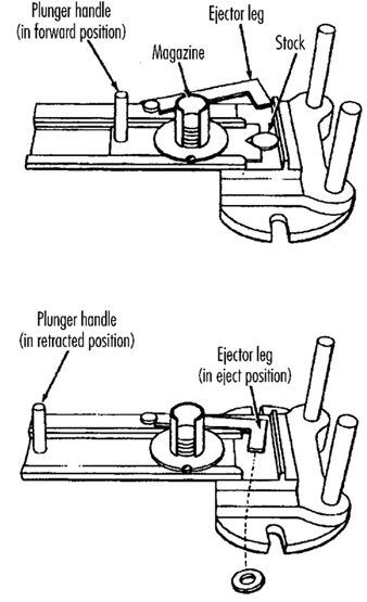
Robots. Robots are complex devices that load and unload stock, assemble parts, transfer objects or perform work otherwise done by an operator, thereby eliminating operator exposure to hazards. They are best used in high-production processes requiring repeated routines, where they can guard against other hazards to employees. Robots may create hazards, and appropriate guards must be used. Figure 32 shows an example of a robot feeding a press.
Figure 32. Using barrier guards to protect robot envelope
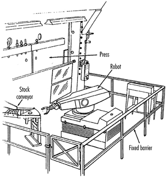
Miscellaneous safeguarding aids
Although miscellaneous safeguarding aids do not give complete protection from machine hazards, they may provide operators with an extra margin of safety. Sound judgement is needed in their application and use.
Awareness barriers. Awareness barriers do not provide physical protection, but serve only to remind operators that they are approaching the danger area. Generally, awareness barriers are not considered adequate when continual exposure to the hazard exists. Figure 33 shows a rope used as an awareness barrier on the rear of a power squaring shear. Barriers do not physically prevent persons from entering danger areas, but only provide awareness of the hazard.
Figure 33. Rear view of power shearing square
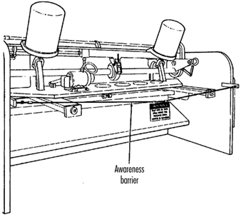
Shields. Shields may be used to provide protection from flying particles, splashing metal-working fluids or coolants. Figure 34 shows two potential applications.
Figure 34. Applications of shields
Holding tools. Holding tools place and remove stock. A typical use would be for reaching into the danger area of a press or press brake. Figure 35 shows an assortment of tools for this purpose. Holding tools should not be used instead of other machine safeguards; they are merely a supplement to the protection that other guards provide.
Figure 35. Holding tools
Push sticks or blocks, such as shown in figure 36, may be used when feeding stock into a machine, such as a saw blade. When it becomes necessary for hands to be in close proximity to the blade, the push stick or block may provide a margin of safety and prevent injury.
Figure 36. Use of push stick or push block
Presence Detectors
General developments in microelectronics and in the technology of sensors give reason to hope that an improvement in occupational safety can be achieved through the availability of reliable, hardy, low-maintenance and inexpensive presence and approach detectors. This article will describe sensor technology, the different detection procedures, the conditions and restrictions applicable to the use of sensor systems, and some completed studies and standardization work in Germany.
Presence Detector Criteria
The development and practical testing of presence detectors is one of the greatest future challenges to technical efforts in improving occupational safety and to the protection of personnel in general. Presence detectors are sensors that reliably and with certainty signal the near presence or approach of a person. In addition, this warning must occur rapidly so that evasive action, braking or the shutting off of a stationary machine can take place before the predicted contact occurs. Whether the people are big or small, whatever their posture, or how they are clothed should have no effect on the reliability of the sensor. In addition, the sensor must possess certainty of functioning and be sturdy and inexpensive, so that it can be used under the most demanding conditions, such as on construction sites and for mobile applications, with minimal maintenance. Sensors must be like an airbag in that they are maintenance-free and always ready. Given some users’ reluctance to maintain what they may regard as nonessential equipment, sensors may be left unserviced for years. Another feature of presence detectors, one that is much more likely to be requested, is that they also detect obstacles other than human beings and alert the operator in time to take defensive action, thus reducing costs of repair and material damage. This is a reason for installing presence detectors that should not be under-appreciated.
Detector Applications
Innumerable fatal accidents and serious injuries which look like unavoidable, individual acts of fate, may be avoided or minimized provided that presence detectors become more accepted as a prevention measure in the field of occupational safety. The newspapers report these accidents all too often: here a person was struck by a backwards-moving loader, there the operator did not see someone who was run over by the front wheel of a power shovel. Trucks moving backwards on streets, company premises and construction sites are the cause of many accidents to people. Today’s thoroughly rationalized companies no longer provide co-drivers or other persons to act as guides for the driver who is backing up a truck. These examples of moving accidents can be easily extended to other mobile equipment, such as fork-lift trucks. However, the use of sensors is urgently needed to prevent accidents involving semi-mobile and purely stationary equipment. An example is the rear areas of large loading machines, which have been identified by safety personnel as potentially hazardous areas which could be improved through the use of inexpensive sensors. Many variations of presence detectors can be adapted innovatively to other vehicles and large mobile equipment to protect against the types of accidents discussed in this article, which generally cause extensive damage and serious, if not fatal, injuries.
The tendency of innovative solutions to become more widespread would seem to promise that presence detectors will become the standard safety technology in other applications; however, this is not the case anywhere. The breakthrough, motivated by accidents and high material damages, is expected in monitoring behind delivery vans and heavy trucks and for the most innovative areas of the “new technologies”—the mobile robot machines of the future.
The variation of the fields of application for presence detectors and the variability of the tasks—for example, tolerating objects (even moving objects, under certain conditions) that belong to a detection field and that should not trigger a signal—require sensors in which “intelligent” assessment technology supports the mechanisms of sensor function. This technology, which is a matter for future development, can be elaborated from methods drawing upon the field of artificial intelligence (Schreiber and Kuhn 1995). To date, a limited universality has severely restricted current uses of sensors. There are light curtains; light bars; contact mats; passive infrared sensors; ultrasound and radar motion detectors that use the Doppler effect; sensors that make elapsed time measurements of ultrasound, radar and light impulses; and laser scanners. Normal television cameras connected to monitors are not included in this list because they are not presence detectors. However, those cameras which do activate automatically upon sensing the presence of a person, are included.
Sensor Technology
Today the main sensor issues are (1) optimizing the use of the physical effects (infrared, light, ultrasound, radar, etc.) and (2) self-monitoring. Laser scanners are being intensively developed for use as navigational instruments for mobile robots. For this, two tasks, partially different in principle, must be solved: the navigation of the robot and the protection of persons (and material or equipment) present so that they are not struck, run over or grabbed (Freund, Dierks and Rossman 1993). Future mobile robots cannot retain the same safety philosophy of “spatial separation of robot and person” which is strictly applied to today’s stationary industrial robots. This means putting a high premium on the reliable functioning of the presence detector to be used.
The use of “new technology” is often linked to problems of acceptance, and it can be assumed that the general use of mobile robots that can move and grasp, among people in plants, in public traffic areas, or even in homes or recreational areas, will be accepted only if they are equipped with very highly developed, sophisticated and reliable presence detectors. Spectacular accidents must be avoided at all costs in order to avoid exacerbating a possible acceptance problem. The current level of expenditure for the development of this type of occupational protective sensors does not come close to taking this consideration into account. To save a lot of costs, presence detectors should be developed and tested simultaneously with the mobile robots and the navigational systems, not afterwards.
With respect to motor vehicles, safety questions have gained increasing significance. Innovative passenger safety in automobiles includes three-point seat belts, child seats, airbags and the anti-lock brake system verified by serial crash tests. These safety measures represent a relatively increasing portion of production costs. The side airbag and radar sensor systems to measure the distance to the car ahead are evolutionary developments in passenger protection.
External motor vehicle safety—that is, the protection of third parties—is receiving increased attention. Recently, side protection has been required, primarily for trucks, to prevent motorcyclists, bicyclists and pedestrians from the danger of falling under the rear wheels. A next logical step would be monitoring the area behind large vehicles with presence detectors and installing rear area warning equipment. This would have the positive side effect of providing the funding required to develop, test and make available maximum performance, self-monitoring, maintenance-free and reliably functioning, inexpensive sensors for occupational safety purposes. The trial process that would go with the broad implementation of sensors or sensor systems would considerably facilitate innovation in other areas, such as power shovels, heavy loaders and other large mobile machines that back up as much as half the time during their operation. The evolutionary process from stationary robots to mobile robots is an additional path of development for presence detectors. For example, improvements could be made to the sensors currently used on mobile robot material movers or “driverless factory floor tractors”, which follow fixed paths and therefore have relatively low safety requirements. The use of presence detectors is the next logical step in improving safety in the area of material and passenger transport.
Detection Procedures
Various physical principles, available in connection with electronic measuring and self-monitoring methods and, to an extent, high-performance computing procedures, may be used to assess and solve the above-mentioned tasks. The apparently effortless and sure operation of automated machines (robots) so common in science-fiction films, will possibly be accomplished in the real world through the use of imaging techniques and high-performance pattern recognition algorithms in combination with distance measurement methods analogous to those employed by laser scanners. The paradoxical situation that everything that seems simple for people is difficult for automatons, must be recognized. For example, a difficult task such as excellent chess playing (which calls for forebrain activity) can be more easily simulated and carried out by automated machines than a simple task such as walking upright or carrying out hand-eye and other movement coordination (mediated by the mid- and hindbrain). A few of these principles, methods and procedures applicable to sensor applications are described below. In addition to these, there are a large number of special procedures for very special tasks that work in part with a combination of various types of physical effects.
Light barrier curtains and bars. Among the first presence detectors were light barrier curtains and bars. They have a flat monitoring geometry; that is, one who has passed the barrier will no longer be detected. An operator’s hand, or the presence of tools or parts held in an operator’s hand, for instance, can be quickly and reliably detected with these devices. They offer an important contribution to occupational safety for machines (like presses and punching machines) that require that material be put in by hand. The reliability has to be extremely high statistically, because when the hand reaches in only two to three times per minute, about one million operations are performed in just a few years. The mutual self-monitoring of sender and receiver components has been developed to such a very high technical level that it represents a standard for all other presence detection procedures.
Contact mats (switch mats). There are both passive and active (pump) types of electric and pneumatic contact mats and floors, which were initially used in large numbers in service functions (door openers), until they were replaced by motion detectors. Further development evolves with the use of presence detectors in all sorts of danger zones. For example, the development of automated manufacturing with a change in the function of the worker—from operating the machine to strictly monitoring its function—produced a corresponding demand for appropriate detectors. Standardization of this use is well advanced (DIN 1995a), and special limitations (layout, size, maximum allowed “dead” zones) necessitated the development of expertise for installation in this area of usage.
Interesting possible uses of contact mats arise in conjunction with computer-controlled multiple robot systems. An operator switches one or two elements so that the presence detector would pick up his or her exact position and inform the computer, which manages robot control systems with a built-in collision-avoidance system. In one test advanced by the German federal safety institute (BAU), a contact-mat floor, consisting of small electrical switch mats, was built under the robot arm’s work area for this purpose (Freund, Dierks and Rossman 1993). This presence detector had the form of a chessboard. The respectively activated mat field told the computer the operator’s position (figure 1) and when the operator approached too close to the robot, it moved away. Without the presence detector the robot system would not be able to ascertain the operator’s position, and the operator then could not be protected.
Figure 1. A person (right) and two robots in computed wrapper bodies
Reflectors (motion sensors and presence detectors). However meritorious the sensors discussed up to now may be, they are not presence detectors in the broader sense. Their suitability—primarily for reasons of occupational safety—for large vehicles and large mobile equipment presupposes two important characteristics: (1) the ability to monitor an area from one position, and (2) error-free functioning without the need for additional measures on the part of—for example, the use of reflector devices. Detecting the presence of a person entering the monitored area and remaining stopped until this person has gone also implies the need for detecting a person standing absolutely still. This distinguishes so-called motion sensors from presence detectors, at least in connection with mobile equipment; motion sensors are almost always triggered when the vehicle is put into motion.
Motion sensors. The two basic types of motion sensors are: (1) “passive infrared sensors” (PIRS), which react to the smallest change in the infrared beam in the monitored area (the smallest detectable beam is approximately 10-9 W with a wavelength range of approximately 7 to 20 μm); and (2) ultrasound and microwave sensors using the Doppler principle, which determines the characteristics of an object’s motion according to the frequency changes. For example, the Doppler effect increases the frequency of a locomotive’s horn for an observer when it is approaching, and reduces the frequency when the locomotive is moving away. The Doppler effect makes possible the building of relatively simple approach sensors, as the receiver needs only to monitor the signal frequency of neighbouring frequency bands for the appearance of the Doppler frequency.
In the mid-1970s the use of motion detectors became prevalent in service function applications such as door openers, theft security and object protection. For stationary use, the detection of an approaching person toward a danger spot was adequate to give a timely warning or to turn off a machine. This was the basis for studying the suitability of motion detectors for their use in occupational safety, especially by means of PIRS (Mester et al. 1980). Because a clothed person generally has a higher temperature than the surrounding area (head 34°C, hands 31°C), detecting an approaching person is somewhat easier than detecting inanimate objects. To a limited extent, machine parts can move about in the monitored area without triggering the detector.
The passive method (without transmitter) has advantages and disadvantages. The advantage is that a PIRS does not add to noise and electrical smog problems. For theft security and object protection, it is particularly important that the detector not be easy to find. A sensor that is purely a receiver, however, can hardly monitor its own effectiveness, which is essential for occupational safety. One method for overcoming this drawback was to test small modulated (5 to 20 Hz) infrared emitters that were installed in the monitored area and that did not trigger the sensor, but whose beams were registered with a fixed electronic amplification set to the modulation frequency. This modification turned it from a “passive” sensor to an “active” sensor. In this way it was also possible to check the geometric accuracy of the monitored area. Mirrors can have blind spots, and a passive sensor’s direction can be thrown off by the rough activity in a plant. Figure 2 shows a test layout with a PIRS with a monitored geometry in the form of a pyramid mantle. Because of their great reach, passive infrared sensors are installed, for example, in the passageways of shelf storage areas.
Figure 2. Passive infrared sensor as approach detector in a danger area
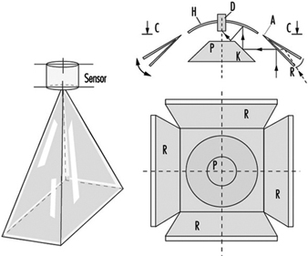
Overall, tests showed that motion detectors are not suited to occupational safety. A night-time museum floor cannot be compared to danger zones in a workplace.
Ultra-sound, radar and light-impulse detectors. Sensors that use the pulse/echo principle—that is, elapsed time measurements of ultrasound, radar or light impulses—have great potential as presence detectors. With laser scanners, light impulses can sweep in rapid succession (usually in a rotatory fashion), for example, horizontally, and with the help of a computer one can obtain a distance profile of the objects on a plane that reflect light. If, for example, not only a single line is wanted, but the entirety of what lies before the mobile robot in the area up to a height of 2 metres, then great quantities of data must be processed to depict the surrounding area. A future “ideal” presence detector will consist of a combination of the following two processes:
- A pattern-recognition process will be employed, consisting of a camera and a computer. The latter can also be a “neuronal net”.
- A laser scanning process is further required to measure distances; this takes a bearing in a three-dimensional space over from a number of individual points selected by the pattern-recognition process, established to obtain the distance and motion by speed and direction.
Figure 3 shows, from the previously cited BAU project (Freund, Dierks and Rossman 1993), the use of a laser scanner on a mobile robot that also assumes navigational tasks (via a direction-sensing beam) and collision protection for objects in the immediate vicinity (via a ground measurement beam for presence detection). Given these features, the mobile robot has the capability of active automated free driving (i.e., the ability to drive around obstacles). Technically, this is achieved by utilizing the 45° angle of the scanner rotation toward the rear on both sides (to port and starboard of the robot) in addition to the 180° angle toward the front. These beams are connected with a special mirror which acts as a light curtain on the floor in front of the mobile robot (providing a ground vision line). If a laser reflection comes from there, the robot stops. While laser and light scanners certified for occupational safety use are on the market, these presence detectors have great potential for further development.
Figure 3. Mobile robot with laser scanner for navigation and presence detection use
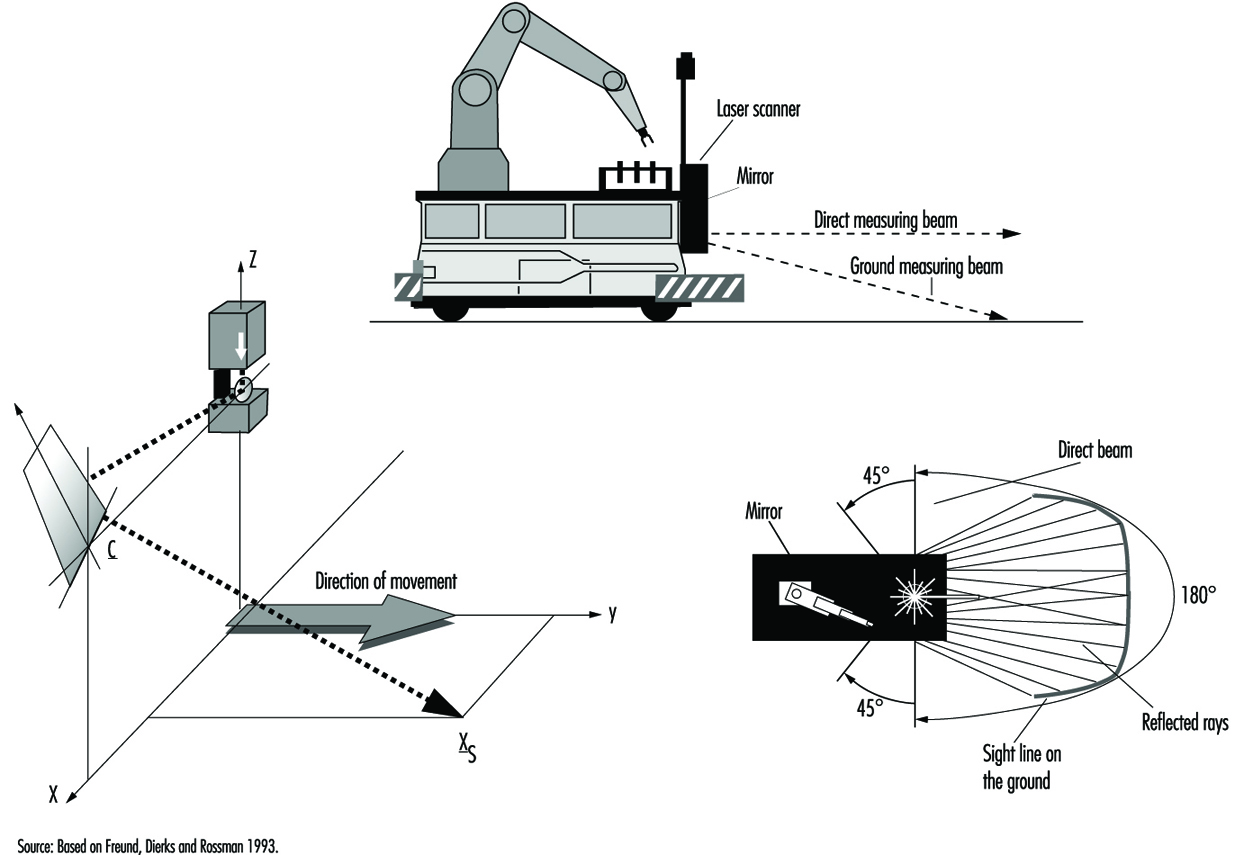
Ultrasound and radar sensors, which use the elapsed time from signal to response to determine distance, are less demanding from a technical perspective and thus can be produced more cheaply. The sensor area is club-shaped and has one or more smaller side clubs, which are symmetrically arranged. The speed of the signal’s spread (sound: 330 m/s; electromagnetic wave: 300,000 km/s) determines the requisite speed of the electronics utilized.
Rear-area warning devices. At the 1985 Hanover Exposition, BAU showed the results of an initial project on the use of ultrasound sensors for securing the area behind large vehicles (Langer and Kurfürst 1985). A full-sized model of a sensor head made of Polaroid™ sensors was set up on the back wall of a supply truck. Figure 4 shows its functioning schematically. The large diameter of this sensor produces relatively small-angled (approximately 18°), long-range club-shaped measured areas, arranged next to each other and set to different maximum signal ranges. In practice it allows one to set any desired monitored geometry, which is scanned by the sensors approximately four times per second for the presence or entrance of persons. Other demonstrated rear-area warning systems had several parallel individual arrayed sensors.
Figure 4. Disposition of measuring head and area monitored on the rear side of a truck
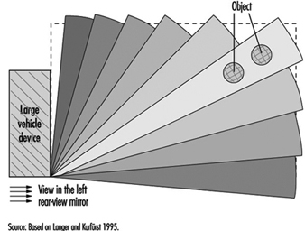
This vivid demonstration was a great success at the exhibition. It showed that securing the rear area of large vehicles and equipment is being studied in many places—for example, by specialized committees of the industrial trade associations (Berufsgenossenschaften), the municipal accident insurers (who are responsible for municipal vehicles), the state industry oversight officials, and the producers of sensors, who had been thinking more in terms of automobiles as service vehicles (in the sense of focusing on parking systems to protect against auto body damage). An ad hoc committee drawn from the groups to promote rear-area warning devices was formed spontaneously and took as a first task the preparation of a list of requirements from the perspective of occupational safety. Ten years have passed during which time much has been worked out in rear-area monitoring—possibly the most important task of presence detectors; but the big breakthrough is still missing.
Many projects have been conducted with ultrasound sensors—for example, on round-wood sorting cranes, hydraulic shovels, special municipal vehicles, and other utility vehicles, as well as on fork-lift trucks and loaders (Schreiber 1990). Rear-area warning devices are especially important for large machinery that backs up much of the time. Ultrasound presence detectors are used, for example, for the protection of specialized driverless vehicles such as robot material-handling machines. As compared to rubber bumpers, these sensors have a greater detection area which provides for braking before contact is made between the machine and an object. Corresponding sensors for automobiles are appropriate developments and involve considerably less stringent requirements.
In the meantime, the Transportation System Technical Standards Committee of DIN worked up Standard 75031, “Obstacle detection devices during reversing” (DIN 1995b). The requirements and tests were set for two ranges: 1.8 m for supply trucks and 3.0 m—an additional warning area—for larger trucks. The monitored area is set through the recognition of cylindrical test bodies. The 3-m range is also about the limit of what is presently technically possible, as ultrasound sensors must have closed metal membranes, given their rough working conditions. The requirements for the sensor system’s self-monitoring are being set, as the required monitored geometry can be accomplished only with a system of three or more sensors. Figure 5 shows a rear-area warning device consisting of three ultrasound sensors (Microsonic GmbH 1996). The same applies for the notification device in the driver’s cab and the type of warning signal. The contents of DIN Standard 75031 are also laid out in the international technical ISO Report TR 12155, “Commercial vehicles—Obstacle detection device during reversing” (ISO 1994). Various sensor producers have developed prototypes in accordance with this standard.
Figure 5. Mid-sized truck equipped with a rear area warning device (Microsonic photo).
Conclusion
Since the early 1970s, several institutions and sensor manufacturers have worked to develop and establish “presence detectors”. In the special application of “rear-area warning devices” there are DIN Standard 75031 and ISO Report TR 12155. At present Deutsche Post AG is conducting a major test. Several sensor manufacturers have each equipped five mid-size trucks with such devices. A positive outcome of this test is very much in the interests of occupational safety. As was emphasized at the outset, presence detectors in the required numbers are a big challenge for safety technology in the many areas of application mentioned. They must therefore be realizable at low cost if damages to equipment, machinery and materials, and, above all, injuries to people, often very serious, are to be relegated to the past.
Devices for Controlling, Isolating and Switching Energy
Control devices and devices used for isolating and switching must always be discussed in relation to technical systems, a term used in this article to include machines, installations and equipment. Every technical system fulfils a specific and assigned practical task. Appropriate safety control and switching devices are required if this practical task is to be workable or even possible under safe conditions. Such devices are used in order to initiate control, interrupt or retard the current and/or the impulses of electric, hydraulic, pneumatic and also potential energies.
Isolation and Energy Reduction
Isolating devices are used to isolate energy by disconnecting the supply line between the energy source and the technical system. The isolating device must normally yield an unequivocally determinable actual disconnection of the energy supply. Disconnection of the energy supply should also always be combined with the reduction of energy stored in all parts of the technical system. If the technical system is fed by several energy sources, all these supply lines must be capable of being reliably isolated. Persons trained to handle the relevant type of energy and who work at the energy end of the technical system, use isolation devices to shield themselves from the hazards of the energy. For safety reasons, these persons will always check to assure that no potentially hazardous energy remains in the technical system—for instance, by ascertaining the absence of electrical potential in the case of electric energy. Risk-free handling of certain isolating devices is possible only for trained specialists; in such cases, the isolating device must be made inaccessible to unauthorized persons. (See figure 1.)
Figure 1. Principles of electric and pneumatic isolating devices
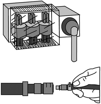
The Master Switch
A master-switch device disconnects the technical system from the energy supply. Unlike the isolating device, it can be operated without danger even by “non-energy specialists”. The master- switch device is used to disconnect technical systems not in use at a given moment should, say, their operation be obstructed by unauthorized third persons. It is also used to effect a disconnection for such purposes as maintenance, repair of malfunctions, cleaning, resetting and refitting, provided that such work can be done without energy in the system. Naturally, when a master-switch device also possesses the characteristics of an isolating device, it can also take on and/or share its function. (See figure 2.)
Figure 2. Sample illustration of electric and pneumetic master-switch devices
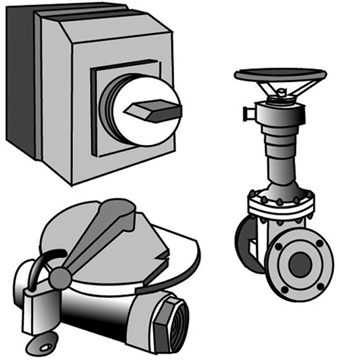
Safety-disconnection Device
A safety-disconnection device does not disconnect the entire technical system from the energy source; rather, it removes energy from the parts of the system critical to a particular operational subsystem. Interventions of short duration can be designated for operational subsystems—for instance, for the set-up or resetting/refitting of the system, for the repair of malfunctions, for regular cleaning, and for essential and designated movements and function sequences required during the course of set-up, resetting/refitting or test runs. Complex production equipment and plants cannot simply be shut off with a master-switch device in these cases, as the entire technical system could not start up again where it left off after a malfunction has been repaired. Furthermore, the master-switch device is rarely located, in the more extensive technical systems, at the place where the intervention must be made. Thus the safety disconnection device is obliged to fulfil a number of requirements, such as the following:
- It interrupts the energy flow reliably and in such a way that dangerous movements or processes are not triggered by control signals which are either erroneously entered or erroneously generated.
- It is installed precisely where interruptions must be made in danger areas of operational subsystems of the technical system. If necessary, installation can be in several places (for instance, on various floors, in various rooms, or at various access points on machinery or equipment).
- Its control device has a clearly marked “off” position which registers only once after the flow of energy has been reliably cut off.
- Once in the “off” position its control device can be secured against being restarted without authorization (a) if the danger areas in question cannot be reliably overseen from the control area and (b) if persons located in the danger area cannot themselves see the control device readily and constantly, or (c) if lock-out/tag-out is required by regulation or organization procedures.
- It should disconnect only a single functional unit of an extended technical system, if other functional units are able to continue to work on their own without danger to the person intervening.
Where the master-switch device used in a given technical system is able to fulfil all the requirements of a safety-disconnection device, it can also take on this function. But that will of course be a reliable expedient only in very simple technical systems. (See figure 3.)
Figure 3. Illustration of elementary principles of a safety disconnection device
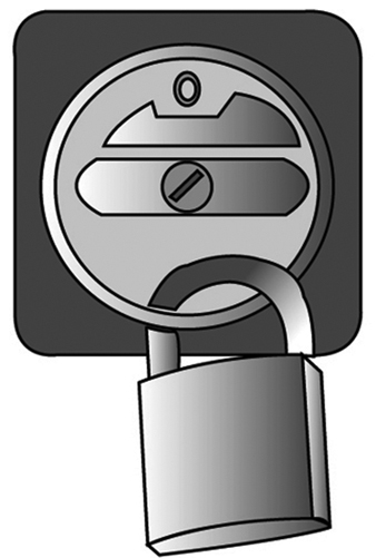
Control Gears for Operational Subsystems
Control gears permit movements and functional sequences required for operational subsystems of the technical system to be implemented and controlled safely. Control gears for operational subsystems may be required for set-up (when test runs are to be executed); for regulation (when malfunctions in the operation of the system are to be repaired or when blockages must be cleared); or training purposes (demonstrating operations). In such cases, the normal operation of the system cannot simply be restarted, as the intervening person would be endangered by movements and processes triggered by control signals either erroneously entered or erroneously generated. A control gear for operational subsystems must conform to the following requirements:
- It should permit the safe execution of movements and processes required for operational subsystems of the technical system. For example, certain movements will be executed at reduced speeds, gradually or at lower levels of power (depending on what is appropriate), and processes interrupted immediately, as a rule, if the control panel is no longer attended.
- Its control panels are to be located in areas where their operation does not endanger the operator, and from which the processes controlled are fully visible.
- If several control panels controlling various processes are present at a single location, then these must be clearly marked and arranged in a distinct and understandable manner.
- The control gear for operational subsystems should become effective only when normal operation has been reliably disengaged; that is, it must be guaranteed that no control command can issue effectively from normal operation and over-ride the control gear.
- Unauthorized use of the control gear for operational subsystems should be preventable, for instance, by requiring the use of a special key or code to release the function in question. (See figure 4.)
Figure 4. Actuating devices in the control gears for movable and stationary operational subsystems
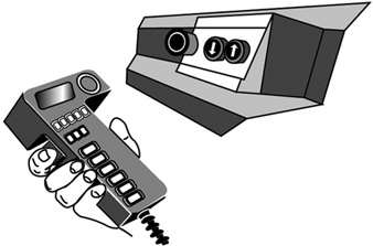
The Emergency Switch
Emergency switches are necessary where the normal operation of technical systems could result in hazards which neither appropriate system design nor the taking of appropriate safety precautions are able to prevent. In operational subsystems, the emergency switch is frequently part of the operational subsystem control gear. When operated in case of danger, the emergency switch implements processes which return the technical system to a safe operating state as quickly as possible. With regard to safety priorities, the protection of persons is of primary concern; prevention of damage to material is secondary, unless the latter is liable to endanger persons as well. The emergency switch must fulfil the following requirements:
- It must bring about a safe operating condition of the technical system as quickly as possible.
- Its control panel must be easily recognizable and placed and designed in such a way that it can be operated without difficulty by the endangered persons and can also be reached by others responding to the emergency.
- The emergency processes it triggers must not bring about new hazards; for example, they must not release clamping devices or disconnect magnetic holding fixtures or block safety devices.
- After an emergency switch process has been triggered, the technical system must not be able to be restarted automatically by the resetting of the emergency switch control panel. Rather, the conscious entry of a new function control command must be required. (See figure 5.)
Figure 5. Illustration of the principles of control panels in emergency switches
Function-switch Control Device
Function-switch control devices are used to switch on the technical system for normal operation and to initiate, implement and interrupt the movements and processes designated for normal operation. The function-switch control device is used exclusively in the course of the normal operation of the technical system—that is, during the undisturbed execution of all assigned functions. It is used accordingly by the persons running the technical system. The function-switch control devices must meet the following requirements:
- Their control panels must be accessible and easy to use without danger.
- Their control panels must be clearly and rationally arranged; for example, control knobs should operate “rationally” with regard to controlled movements up and down, right and left. (“Rational” control movements and corresponding effects may be subject to local variation and are sometimes defined by stipulation.)
- Their control panels are to be clearly and intelligibly labelled, with symbols which are easily understood.
- Processes which require the complete attention of the user for their safe execution must not be able to be triggered either by control signals generated in error or by inadvertent operation of the control devices governing them. Control panel signal processing must be appropriately reliable, and involuntary operation must be prevented by appropriate design of the control device. (See figure 6).
Figure 6. Schematic representation of an operations control panel
Monitoring Switches
Monitoring switches prevent the starting of the technical system as long as the monitored safety conditions are not fulfilled, and they interrupt operation as soon as a safety condition is no longer being fulfilled. They are used, for example, to monitor doors in protective compartments, to check for the correct position of safety guards or to assure that speed or path limits are not exceeded. Monitoring switches must accordingly fulfil the following safety and reliability requirements:
- The switching gear used for monitoring purposes must emit the protective signal in a particularly reliable fashion; for instance, a mechanical monitoring switch might be designed to interrupt the signal flow automatically and with particular reliability.
- The switching tool used for monitoring purposes is to be operated in a particularly reliable fashion when the safety condition is not fulfilled (e.g., when the plunger of a monitoring switch with automatic interruption is forced mechanically and automatically into the interrupt position).
- The monitoring switch must not be able to be improperly turned off, at least not unintentionally and not without some effort; this condition may be fulfilled, for instance, by a mechanical, automatically controlled switch with automatic interruption, when the switch and the operating element are securely mounted. (See figure 7).
Figure 7. Diagram of a switch with a positive mechanical operation and positive disconnection
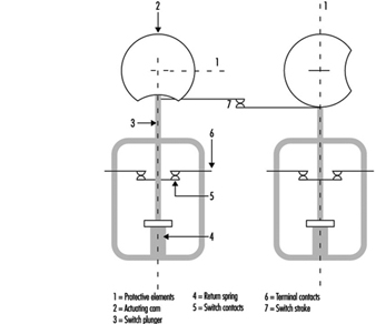
Safety Control Circuits
Several of the safety switching devices described above do not execute the safety function directly, but rather by emitting a signal which is then transmitted and processed by a safety control circuit and finally reaches those parts of the technical system which exercise the actual safety function. The safety-disconnection device, for example, frequently causes the disconnection of energy at critical points indirectly, whereas a main switch usually directly disconnects the supply of current to the technical system.
Because safety control circuits must transmit safety signals reliably, the following principles must therefore be taken into consideration:
- Safety should be guaranteed even when outside energy is lacking or insufficient, for example, during disconnects or leaks.
- Protective signals function more reliably by interruption of the signal flow; for example, safety switches with opener contact or an open relay contact.
- The protective function of amplifiers, transformers and the like may be achieved more reliably without outside energy; such mechanisms include, for example, electromagnetic switching devices or vents that are closed when at rest.
- Connections effected in error and leaks in the safety-control circuit must not be allowed to lead to false starts or hindrances to stoppage; particularly in the cases of a short circuit between in- and out-conduits, earth leakage, or grounding.
- Outside influences affecting the system in a measure not exceeding the expectations of the user should not interfere with the safety function of the safety-control circuit.
The components used in safety-control circuits must execute the safety function in an especially reliable way. The functions of components which do not meet this requirement are to be implemented by arranging for as diversified a redundancy as possible and are to be kept under surveillance.
Safety-Related Applications
In the last few years microprocessors have played an ever-increasing role in the field of safety technology. Because entire computers (i.e., central processing unit, memory and peripheral components) are now available in a single component as “single-chip computers”, microprocessor technology is being employed not only in complex machine control, but also in safeguards of relatively simple design (e.g., light grids, two-hand control devices and safety edges). The software controlling these systems comprises between one thousand and several tens of thousands of single commands and usually consists of several hundred program branches. The programs operate in real time and are mostly written in the programmers’ assembly language.
The introduction of computer-controlled systems in the sphere of safety technology has been accompanied in all large-scale technical equipment not only by expensive research and development projects but also by significant restrictions designed to enhance safety. (Aerospace technology, military technology and atomic power technology may here be cited as examples of large-scale applications.) The collective field of industrial mass production has up to now been treated only in a very limited fashion. This is partly for the reason that the rapid cycles of innovation characteristic of industrial machine design make it difficult to carry over, in any but a very restricted manner, such knowledge as may be derived from research projects concerned with the final testing of large-scale safety devices. This makes the development of rapid and low-cost assessment procedures a desideratum (Reinert and Reuss 1991).
This article first examines machines and facilities in which computer systems presently perform safety tasks, using examples of accidents occurring preponderantly in the area of machine safeguards to depict the particular role which computers play in safety technology. These accidents give some indication as to which precautions must be taken so that the computer-controlled safety equipment currently coming into increasingly wide use will not lead to a rise in the number of accidents. The final section of the article sketches out a procedure which will enable even small computer systems to be brought to an appropriate level of technical safety at justifiable expense and within an acceptable period of time. The principles indicated in this final part are currently being introduced into international standardization procedures and will have implications for all areas of safety technology in which computers find application.
Examples of the Use of Software and Computers in the Field of Machine Safeguards
The following four examples make it clear that software and computers are currently entering more and more into safety-related applications in the commercial domain.
Personal-emergency signal installations consist, as a rule, of a central receiving station and a number of personal emergency signalling devices. The devices are carried by persons working onsite by themselves. If any of these persons working alone find themselves in an emergency situation, they can use the device to trip an alarm by radio signal in the central receiving station. Such a will-dependent alarm trigger may also be supplemented by a will-independent triggering mechanism activated by sensors built into the personal emergency devices. Both the individual devices and the central receiving station are frequently controlled by microcomputers. It is conceivable that failure of specific single functions of the built-in computer could lead, in an emergency situation, to a failure to trip the alarm. Precautions must therefore be taken to perceive and to repair such loss of function in time.
Printing presses used today to print magazines are large machines. The paper webs are normally prepared by a separate machine in such a way as to enable a seamless transition to a new paper roll. The printed pages are folded by a folding machine and subsequently worked through a chain of further machines. This results in pallets loaded with fully sewn magazines. Although such plants are automated, there are two points at which manual interventions must be made: (1) in the threading of the paper paths, and (2) in clearing obstructions caused by paper tears at danger spots on the rotating rollers. For this reason, a reduced speed of operation or a path- or time-limited jogging mode must be ensured by the control technology while the presses are being adjusted. On account of the complex steering procedures involved, every single printing station must be equipped with its own programmable logic controller. Any failure occurring in the control of a printing plant while guard grids are open must be kept from leading either to the unexpected start-up of a stopped machine or to operation in excess of appropriately reduced speeds.
In large factories and warehouses, driverless, automated guided robot vehicles move about on specially marked tracks. These tracks can be walked upon at any time by persons, or materials and equipment may be inadvertently left on the tracks, since they are not separated structurally from other lines of traffic. For this reason, some sort of collision-prevention equipment must be used to ensure that the vehicle will be brought to a halt before any dangerous collision with a person or object occurs. In more recent applications, collision prevention is effected by means of ultrasonic or laser light scanners used in combination with a safety bumper. Since these systems work under computer control, it is possible to configure several permanent detection zones so that a vehicle can modify its reaction depending on the specific detection zone in which a person is located. Failures in the protective device must not lead to a dangerous collision with a person.
Paper-cutting control device guillotines are used to press and then cut thick stacks of paper. They are triggered by a two-hand control device. The user must reach into the danger zone of the machine after each cut is made. An immaterial safeguard, usually a light grid, is used in conjunction with both the two-hand control device and a safe machine-control system to prevent injuries when paper is fed during the cutting operation. Nearly all the larger, more modern guillotines in use today are controlled by multichannel microcomputer systems. Both the two-hand operation and the light grid must also be guaranteed to function safely.
Accidents with Computer-Controlled Systems
In nearly all fields of industrial application, accidents with software and computers are reported (Neumann 1994). In most cases, computer failures do not lead to injury to persons. Such failures are in any case made public only when they are of general public interest. This means that the instances of malfunction or accident related to computers and software in which injury to persons is involved make up a relatively high proportion of all publicized cases. Unfortunately, accidents which do not cause much of a public sensation are not investigated as to their causes with quite the same intensity as are more prominent accidents, typically in large-scale plants. For this reason, the examples which follow refer to four descriptions of malfunctions or accidents typical of computer-controlled systems outside the field of machine safeguards, which are used to suggest what has to be taken into account when judgements concerning safety technology are made.
Accidents caused by random failures in hardware
The following mishap was caused by a concentration of random failures in the hardware combined with programming failure: A reactor overheated in a chemical plant, whereupon relief valves were opened, allowing the contents of the reactor to be discharged into the atmosphere. This mishap occurred a short time after a warning had been given that the oil level in a gearbox was too low. Careful investigation of the mishap showed that shortly after the catalyst had initiated the reaction in the reactor—in consequence of which the reactor would have required more cooling—the computer, on the basis of the report of low oil levels in the gearbox, froze all magnitudes under its control at a fixed value. This kept the cold water flow at too low a level and the reactor overheated as a result. Further investigation showed that the indication of low oil levels had been signalled by a faulty component.
The software had responded according to the specification with the tripping of an alarm and the fixing of all operative variables. This was a consequence of the HAZOP (hazards and operability analysis) study (Knowlton 1986) done prior to the event, which required that all controlled variables not be modified in the event of a failure. Since the programmer was not acquainted with the procedure in detail, this requirement was interpreted to mean that the controlled actuators (control valves in this case) were not to be modified; no attention was paid to the possibility of a rise in temperature. The programmer did not take into consideration that after having received an erroneous signal the system might find itself in a dynamic situation of a type requiring the active intervention of the computer to prevent a mishap. The situation which led to the mishap was so unlikely, moreover, that it had not been analysed in detail in the HAZOP study (Levenson 1986). This example provides a transition to a second category of causes of software and computer accidents. These are the systematic failures which are in the system from the beginning, but which manifest themselves only in certain very specific situations which the developer has not taken into account.
Accidents caused by operating failures
In field testing during the final inspection of robots, one technician borrowed the cassette of a neighbouring robot and substituted a different one without informing his colleague that he had done so. Upon returning to his workplace, the colleague inserted the wrong cassette. Since he stood next to the robot and expected a particular sequence of movements from it—a sequence which came out differently on account of the exchanged program—a collision occurred between robot and human. This accident describes the classical example of an operating failure. The role of such failures in malfunctions and accidents is currently increasing due to increasing complexity in the application of computer-controlled safety mechanisms.
Accidents caused by systematic failures in hardware or software
A torpedo with a warhead was to have been fired for training purposes, from a warship on the high seas. On account of a defect in the drive apparatus the torpedo remained in the torpedo tube. The captain decided to return to the home port in order to salvage the torpedo. Shortly after the ship had begun to make its way back home, the torpedo exploded. An analysis of the accident revealed that the torpedo’s developers had been obliged to build into the torpedo a mechanism designed to prevent its returning to the launching pad after having been fired and thus destroying the ship that had launched it. The mechanism chosen for this was as follows: After the firing of the torpedo a check was made, using the inertial navigation system, to see whether its course had altered by 180°. As soon as the torpedo sensed that it had turned 180°, the torpedo detonated immediately, supposedly at a safe distance from the launching pad. This detection mechanism was actuated in the case of the torpedo which had not been properly launched, with the result that the torpedo exploded after the ship had changed its course by 180°. This is a typical example of an accident occurring on account of a failure in specifications. The requirement in the specifications that the torpedo should not destroy its own ship should its course change was not formulated precisely enough; the precaution was thus programmed erroneously. The error became apparent only in a particular situation, one which the programmer had not taken into account as a possibility.
On 14 September 1993, a Lufthansa Airbus A 320 crashed while landing in Warsaw (figure 1). A careful investigation of the accident showed that modifications in the landing logic of the on-board computer made after an accident with a Lauda Air Boeing 767 in 1991 were partly responsible for this crash landing. What had happened in the 1991 accident was that the thrust deflection, which diverts some part of the motor gases so as to brake the airplane during landing, had engaged while still in the air, thus forcing the machine into an uncontrollable nose-dive. For this reason, an electronic locking of the thrust deflection had been built into the Airbus machines. This mechanism permitted thrust deflection to come into effect only after sensors on both sets of landing gear had signalled the compression of the shock absorbers under the pressure of the wheels touching down. On the basis of incorrect information, the pilots of the plane in Warsaw anticipated a strong side wind.
Figure 1. Lufthansa Airbus after accident in Warsaw 1993
For this reason they brought the machine in at a slight tilt and the Airbus touched down with the right wheel only, leaving the left bearing less than full weight. On account of the electronic locking of the thrust deflection, the on-board computer denied to the pilot for the space of nine seconds such manoeuvers as would have allowed the airplane to land safely despite adverse circumstances. This accident demonstrates very clearly that modifications in computer systems can lead to new and hazardous situations if the range of their possible consequences is not considered in advance.
The following example of a malfunction also demonstrates the disastrous effects which the modification of one single command can have in computer systems. The alcohol content of blood is determined, in chemical tests, using clear blood serum from which the blood corpuscles have been centrifuged out in advance. The alcohol content of serum is therefore higher (by a factor of 1.2) than that of the thicker whole blood. For this reason the alcohol values in serum must be divided by a factor of 1.2 in order to establish the legally and medically critical parts-per-thousand figures. In the inter-laboratory test held in 1984, the blood alcohol values ascertained in identical tests performed at different research institutions using serum were to have been compared with each other. Since it was a question of comparison only, the command to divide by 1.2 was moreover erased from the program at one of the institutions for the duration of the experiment. After the inter-laboratory test had come to an end, a command to multiply by 1.2 was erroneously introduced into the program at this spot. Roughly 1,500 incorrect parts-per-thousand values were calculated between August 1984 and March 1985 as a result. This error was critical for the professional careers of truck drivers with blood alcohol levels between 1.0 and 1.3 per thousand, since a legal penalty entailing confiscation of a driver’s licence for a prolonged period is the consequence of a 1.3 per thousand value.
Accidents caused by influences from operating stresses or from environmental stresses
As a consequence of a disturbance caused by collection of waste in the effective area of a CNC (computer numeric control) punching and nibbling machine, the user put into effect the “programmed stop”. As he was trying to remove the waste with his hands, the push rod of the machine started moving in spite of the programmed stop and severely injured the user. An analysis of the accident revealed that it had not been a question of an error in the program. The unexpected start-up could not be reproduced. Similar irregularities had been observed in the past on other machines of the same type. It seems plausible to deduce from these that the accident must have been caused by electromagnetic interference. Similar accidents with industrial robots are reported from Japan (Neumann 1987).
A malfunction in the Voyager 2 space probe on January 18, 1986, makes even more clear the influence of environmental stresses on computer-controlled systems. Six days before the closest approach to Uranus, large fields of black-and-white lines covered over the pictures from Voyager 2. A precise analysis showed that a single bit in a command word of the flight data subsystem had caused the failure, observed as the pictures were compressed in the probe. This bit had most likely been knocked out of place within the program memory by the impact of a cosmic particle. Error-free transmission of the compressed photographs from the probe was effected only two days later, using a replacement program capable of bypassing the failed memory point (Laeser, McLaughlin and Wolff 1987).
Summary of the accidents presented
The accidents analysed show that certain risks that might be neglected under conditions using simple, electro-mechanical technology, gain in significance when computers are used. Computers permit the processing of complex and situation-specific safety functions. An unambiguous, error-free, complete and testable specification of all safety functions becomes for this reason especially important. Errors in specifications are difficult to discover and are frequently the cause of accidents in complex systems. Freely programmable controls are usually introduced with the intention of being able to react flexibly and quickly to the changing market. Modifications, however—particularly in complex systems—have side effects which are difficult to foresee. All modifications must therefore be subjected to a strictly formal management of change procedure in which a clear separation of safety functions from partial systems not relevant to safety will help keep the consequences of modifications for safety technology easy to survey.
Computers work with low levels of electricity. They are therefore susceptible to interference from external radiation sources. Since the modification of a single signal among millions can lead to a malfunction, it is worth paying special attention to the theme of electromagnetic compatibility in connection with computers.
The servicing of computer-controlled systems is currently becoming more and more complex and thus more unclear. The software ergonomics of user and configuration software is therefore becoming more interesting from the point of view of safety technology.
No computer system is 100% testable. A simple control mechanism with 32 binary input ports and 1,000 different software paths requires 4.3 × 10¹² tests for a complete check. At a rate of 100 tests per second executed and evaluated, a complete test would take 1,362 years.
Procedures and Measures for the Improvement of Computer-Controlled Safety Devices
Procedures have been developed within the last 10 years which permit mastery of specific safety-related challenges in connection with computers. These procedures address themselves to the computer failures described in this section. The examples described of software and computers in machine safeguards and the accidents analysed, show that the extent of damage and thus also the risk involved in various applications are extremely variable. It is therefore clear that the requisite precautions for the improvement of computers and software used in safety technology should be established in relation to the risk.
Figure 2 shows a qualitative procedure whereby the necessary risk reduction obtainable using safety systems can be determined independently of the extent to which and the frequency with which damage occurs (Bell and Reinert 1992). The types of failures in computer systems analysed in the section “Accidents with computer-controlled systems” (above) may be brought into relation with the so-called Safety Integrity Levels—that is, the technical facilities for risk reduction.
Figure 2. Qualitative procedure for risk determination
Figure 3 makes it clear that the effectiveness of measures taken, in any given case, to reduce error in software and computers needs to grow with increasing risk (DIN 1994; IEC 1993).
Figure 3, Effectiveness of precautions taken against errors independently of risk
The analysis of the accidents sketched above shows that the failure of computer-controlled safeguards is caused not only by random component faults, but also by particular operating conditions which the programmer has failed to take into account. The not immediately obvious consequences of program modifications made in the course of system maintenance constitute a further source of error. It follows that there can be failures in safety systems controlled by microprocessors which, though made during the development of the system, can lead to a dangerous situation only during operation. Precautions against such failures must therefore be taken while safety-related systems are in the development stage. These so-called failure-avoidance measures must be taken not only during the concept phase, but also in the process of development, installation and modification. Certain failures can be avoided if they are discovered and corrected during this process (DIN 1990).
As the last mishap described makes clear, the breakdown of a single transistor can lead to the technical failure of highly complex automated equipment. Since each single circuit is composed of many thousands of transistors and other components, numerous failure-avoidance measures must be taken to recognize such failures as turn up in operation and to initiate an appropriate reaction in the computer system. Figure 4 describes types of failures in programmable electronic systems as well as examples of precautions which may be taken to avoid and control failures in computer systems (DIN 1990; IEC 1992).
Figure 4. Examples of precautions taken to control and avoid errors in computer systems
Possibilities and Prospects of Programmable Electronic Systems in Safety Technology
Modern machines and plants are becoming increasingly complex and must achieve ever more comprehensive tasks in ever shorter periods of time. For this reason, computer systems have taken over nearly all areas of industry since the mid-1970s. This increase in complexity alone has contributed significantly to the rising costs involved in improving safety technology in such systems. Although software and computers pose a great challenge to safety in the workplace, they also make possible the implementation of new error-friendly systems in the field of safety technology.
A droll but instructive verse by Ernst Jandl will help to explain what is meant by the concept error-friendly. “Lichtung: Manche meinen lechts und rinks kann man nicht velwechsern, werch ein Illtum”. (“Dilection: Many berieve light and reft cannot be intelchanged, what an ellol”.) Despite the exchange of the letters r and l, this phrase is easily understood by a normal adult human. Even someone with low fluency in the English language can translate it into English. The task is, however, nearly impossible for a translating computer on its own.
This example shows that a human being can react in a much more error-friendly fashion than a language computer can. This means that humans, like all other living creatures, can tolerate failures by referring them to experience. If one looks at the machines in use today, one can see that the majority of machines penalize user failures not with an accident, but with a decrease in production. This property leads to the manipulation or evasion of safeguards. Modern computer technology places systems at the disposal of work safety which can react intelligently—that is, in a modified way. Such systems thus make possible an error-friendly mode of behaviour in novel machines. They warn users during a wrong operation first of all and shut the machine off only when this is the only way to avoid an accident. The analysis of accidents shows that there exists in this area a considerable potential for reducing accidents (Reinert and Reuss 1991).
Software and Computers: Hybrid Automated Systems
A hybrid automated system (HAS) aims to integrate the capabilities of artificially intelligent machines (based on computer technology) with the capacities of the people who interact with these machines in the course of their work activities. The principal concerns of HAS utilization relate to how the human and machine subsystems should be designed in order to make the best use of the knowledge and skills of both parts of the hybrid system, and how the human operators and machine components should interact with each other to assure their functions complement one another. Many hybrid automated systems have evolved as the products of applications of modern information- and control-based methodologies to automate and integrate different functions of often complex technological systems. HAS was originally identified with the introduction of computer-based systems used in the design and operation of real-time control systems for nuclear power reactors, for chemical processing plants and for discrete parts-manufacturing technology. HAS can now also be found in many service industries, such as air traffic control and aircraft navigation procedures in the civil aviation area, and in the design and use of intelligent vehicle and highway navigation systems in road transportation.
With continuing progress in computer-based automation, the nature of human tasks in modern technological systems shifts from those that require perceptual-motor skills to those calling for cognitive activities, which are needed for problem solving, for decision making in system monitoring, and for supervisory control tasks. For example, the human operators in computer-integrated manufacturing systems primarily act as system monitors, problem solvers and decision makers. The cognitive activities of the human supervisor in any HAS environment are (1) planning what should be done for a given period of time, (2) devising procedures (or steps) to achieve the set of planned goals, (3) monitoring the progress of (technological) processes, (4) “teaching” the system through a human-interactive computer, (5) intervening if the system behaves abnormally or if the control priorities change and (6) learning through feedback from the system about the impact of supervisory actions (Sheridan 1987).
Hybrid System Design
The human-machine interactions in a HAS involve utilization of dynamic communication loops between the human operators and intelligent machines—a process that includes information sensing and processing and the initiation and execution of control tasks and decision making—within a given structure of function allocation between humans and machines. At a minimum, the interactions between people and automation should reflect the high complexity of hybrid automated systems, as well as relevant characteristics of the human operators and task requirements. Therefore, the hybrid automated system can be formally defined as a quintuple in the following formula:
HAS = (T, U, C, E, I)
where T = task requirements (physical and cognitive); U = user characteristics (physical and cognitive); C = the automation characteristics (hardware and software, including computer interfaces); E = the system’s environment; I = a set of interactions among the above elements.
The set of interactions I embodies all possible interactions between T, U and C in E regardless of their nature or strength of association. For example, one of the possible interactions might involve the relation of the data stored in the computer memory to the corresponding knowledge, if any, of the human operator. The interactions I can be elemental (i.e., limited to a one-to-one association), or complex, such as would involve interactions between the human operator, the particular software used to achieve the desired task, and the available physical interface with the computer.
Designers of many hybrid automated systems focus primarily on the computer-aided integration of sophisticated machines and other equipment as parts of computer-based technology, rarely paying much attention to the paramount need for effective human integration within such systems. Therefore, at present, many of the computer-integrated (technological) systems are not fully compatible with the inherent capabilities of the human operators as expressed by the skills and knowledge necessary for the effective control and monitoring of these systems. Such incompatibility arises at all levels of human, machine and human-machine functioning, and can be defined within a framework of the individual and the entire organization or facility. For example, the problems of integrating people and technology in advanced manufacturing enterprises occur early in the HAS design stage. These problems can be conceptualized using the following system integration model of the complexity of interactions, I, between the system designers, D, human operators, H, or potential system users and technology, T:
I (H, T) = F [ I (H, D), I (D, T)]
where I stands for relevant interactions taking place in a given HAS’s structure, while F indicates functional relationships between designers, human operators and technology.
The above system integration model highlights the fact that the interactions between the users and technology are determined by the outcome of the integration of the two earlier interactions—namely, (1) those between HAS designers and potential users and (2) those between the designers and the HAS technology (at the level of machines and their integration). It should be noted that even though strong interactions typically exist between the designers and technology, only very few examples of equally strong interrelationships between designers and human operators can be found.
It can be argued that even in the most automated systems, the human role remains critical to successful system performance at the operational level. Bainbridge (1983) identified a set of problems relevant to the operation of the HAS which are due to the nature of automation itself, as follows:
- Operators “out of the control loop”. The human operators are present in the system to exercise control when needed, but by being “out of the control loop” they fail to maintain the manual skills and long-term system knowledge that are often required in case of an emergency.
- Outdated “mental picture”. The human operators may not be able to respond quickly to changes in the system behaviour if they have not been following the events of its operation very closely. Furthermore, the operators’ knowledge or mental picture of the system functioning may be inadequate to initiate or exercise required responses.
- Disappearing generations of skills. New operators may not be able to acquire sufficient knowledge about the computerized system achieved through experience and, therefore, will be unable to exercise effective control when needed.
- Authority of automatics. If the computerized system has been implemented because it can perform the required tasks better than the human operator, the question arises, “On what basis should the operator decide that correct or incorrect decisions are being made by the automated systems?”
- Emergence of the new types of “human errors” due to automation. Automated systems lead to new types of errors and, consequently, accidents which cannot be analysed within the framework of traditional techniques of analysis.
Task Allocation
One of the important issues for HAS design is to determine how many and which functions or responsibilities should be allocated to the human operators, and which and how many to the computers. Generally, there are three basic classes of task allocation problems that should be considered: (1) the human supervisor–computer task allocation, (2) the human–human task allocation and (3) the supervisory computer–computer task allocation. Ideally, the allocation decisions should be made through some structured allocation procedure before the basic system design is begun. Unfortunately such a systematic process is seldom possible, as the functions to be allocated may either need further examination or must be carried out interactively between the human and machine system components—that is, through application of the supervisory control paradigm. Task allocation in hybrid automated systems should focus on the extent of the human and computer supervisory responsibilities, and should consider the nature of interactions between the human operator and computerized decision support systems. The means of information transfer between machines and the human input-output interfaces and the compatibility of software with human cognitive problem-solving abilities should also be considered.
In traditional approaches to the design and management of hybrid automated systems, workers were considered as deterministic input-output systems, and there was a tendency to disregard the teleological nature of human behaviour—that is, the goal-oriented behaviour relying on the acquisition of relevant information and the selection of goals (Goodstein et al. 1988). To be successful, the design and management of advanced hybrid automated systems must be based on a description of the human mental functions needed for a specific task. The “cognitive engineering” approach (described further below) proposes that human-machine (hybrid) systems need to be conceived, designed, analysed and evaluated in terms of human mental processes (i.e., the operator’s mental model of the adaptive systems is taken into account). The following are the requirements of the human-centred approach to HAS design and operation as formulated by Corbett (1988):
- Compatibility. System operation should not require skills unrelated to existing skills, but should allow existing skills to evolve. The human operator should input and receive information which is compatible with conventional practice in order that the interface conform to the user’s prior knowledge and skill.
- Transparency. One cannot control a system without understanding it. Therefore, the human operator must be able to “see” the internal processes of the system’s control software if learning is to be facilitated. A transparent system makes it easy for users to build up an internal model of the decision-making and control functions that the system can perform.
- Minimum shock. The system should not do anything which operators find unexpected in the light of the information available to them, detailing the present state of the system.
- Disturbance control. Uncertain tasks (as defined by the choice structure analysis) should be under human operator control with computer decision-making support.
- Fallibility. The implicit skills and knowledge of the human operators should not be designed out of the system. The operators should never be put in a position where they helplessly watch the software direct an incorrect operation.
- Error reversibility. Software should supply sufficient feedforward of information to inform the human operator of the likely consequences of a particular operation or strategy.
- Operating flexibility. The system should offer human operators the freedom to trade off requirements and resource limits by shifting operating strategies without losing the control software support.
Cognitive Human Factors Engineering
Cognitive human factors engineering focuses on how human operators make decisions at the workplace, solve problems, formulate plans and learn new skills (Hollnagel and Woods 1983). The roles of the human operators functioning in any HAS can be classified using Rasmussen’s scheme (1983) into three major categories:
- Skill-based behaviour is the sensory-motor performance executed during acts or activities which take place without conscious control as smooth, automated and highly integrated patterns of behaviour. Human activities that fall under this category are considered to be a sequence of skilled acts composed for a given situation. Skill-based behaviour is thus the expression of more or less stored patterns of behaviours or pre-programmed instructions in a space-time domain.
- Rule-based behaviour is a goal-oriented category of performance structured by feedforward control through a stored rule or procedure—that is, an ordered performance allowing a sequence of subroutines in a familiar work situation to be composed. The rule is typically selected from previous experiences and reflects the functional properties which constrain the behaviour of the environment. Rule-based performance is based on explicit know-how as regards employing the relevant rules. The decision data set consists of references for recognition and identification of states, events or situations.
- Knowledge-based behaviour is a category of goal-controlled performance, in which the goal is explicitly formulated based on knowledge of the environment and the aims of the person. The internal structure of the system is represented by a “mental model”. This kind of behaviour allows the development and testing of different plans under unfamiliar and, therefore, uncertain control conditions, and is needed when skills or rules are either unavailable or inadequate so that problem solving and planning must be called upon instead.
In the design and management of a HAS, one should consider the cognitive characteristics of the workers in order to assure the compatibility of system operation with the worker’s internal model that describes its functions. Consequently, the system’s description level should be shifted from the skill-based to the rule-based and knowledge-based aspects of human functioning, and appropriate methods of cognitive task analysis should be used to identify the operator’s model of a system. A related issue in the development of a HAS is the design of means of information transmission between the human operator and automated system components, at both the physical and the cognitive levels. Such information transfer should be compatible with the modes of information utilized at different levels of system operation—that is, visual, verbal, tactile or hybrid. This informational compatibility ensures that different forms of information transfer will require minimal incompatibility between the medium and the nature of the information. For example, a visual display is best for transmission of spatial information, while auditory input may be used to convey textual information.
Quite often the human operator develops an internal model that describes the operation and function of the system according to his or her experience, training and instructions in connection with the given type of human-machine interface. In light of this reality, the designers of a HAS should attempt to build into the machines (or other artificial systems) a model of the human operator’s physical and cognitive characteristics—that is, the system’s image of the operator (Hollnagel and Woods 1983). The designers of a HAS must also take into consideration the level of abstraction in the system description as well as various relevant categories of the human operator’s behaviour. These levels of abstraction for modelling human functioning in the working environment are as follows (Rasmussen 1983): (1) physical form (anatomical structure), (2) physical functions (physiological functions), (3) generalized functions (psychological mechanisms and cognitive and affective processes), (4) abstract functions (information processing) and (5) functional purpose (value structures, myths, religions, human interactions). These five levels must be considered simultaneously by the designers in order to ensure effective HAS performance.
System Software Design
Since the computer software is a primary component of any HAS environment, software development, including design, testing, operation and modification, and software reliability issues must also be considered at the early stages of HAS development. By this means, one should be able to lower the cost of software error detection and elimination. It is difficult, however, to estimate the reliability of the human components of a HAS, on account of limitations in our ability to model human task performance, the related workload and potential errors. Excessive or insufficient mental workload may lead to information overload and boredom, respectively, and may result in degraded human performance, leading to errors and the increasing probability of accidents. The designers of a HAS should employ adaptive interfaces, which utilize artificial intelligence techniques, to solve these problems. In addition to human-machine compatibility, the issue of human-machine adaptability to each other must be considered in order to reduce the stress levels that come about when human capabilities may be exceeded.
Due to the high level of complexity of many hybrid automated systems, identification of any potential hazards related to the hardware, software, operational procedures and human-machine interactions of these systems becomes critical to the success of efforts aimed at reduction of injuries and equipment damage. Safety and health hazards associated with complex hybrid automated systems, such as computer-integrated manufacturing technology (CIM), is clearly one of the most critical aspects of system design and operation.
System Safety Issues
Hybrid automated environments, with their significant potential for erratic behaviour of the control software under system disturbance conditions, create a new generation of accident risks. As hybrid automated systems become more versatile and complex, system disturbances, including start-up and shut-down problems and deviations in system control, can significantly increase the possibility of serious danger to the human operators. Ironically, in many abnormal situations, operators usually rely on the proper functioning of the automated safety subsystems, a practice which may increase the risk of severe injury. For example, a study of accidents related to malfunctions of technical control systems showed that about one-third of the accident sequences included human intervention in the control loop of the disturbed system.
Since traditional safety measures cannot be easily adapted to the needs of HAS environments, injury control and accident prevention strategies need to be reconsidered in view of the inherent characteristics of these systems. For example, in the area of advanced manufacturing technology, many processes are characterized by the existence of substantial amounts of energy flows which cannot be easily anticipated by the human operators. Furthermore, safety problems typically emerge at the interfaces between subsystems, or when system disturbances progress from one subsystem to another. According to the International Organization for Standardization (ISO 1991), the risks associated with hazards due to industrial automation vary with the types of industrial machines incorporated into the specific manufacturing system and with the ways in which the system is installed, programmed, operated, maintained and repaired. For example, a comparison of robot-related accidents in Sweden to other types of accidents showed that robots may be the most hazardous industrial machines used in advanced manufacturing industry. The estimated accident rate for industrial robots was one serious accident per 45 robot-years, a higher rate than that for industrial presses, which was reported to be one accident per 50 machine-years. It should be noted here that industrial presses in the United States accounted for about 23% of all metalworking machine-related fatalities for the 1980–1985 period, with power presses ranked first with respect to the severity-frequency product for non-fatal injuries.
In the domain of advanced manufacturing technology, there are many moving parts which are hazardous to workers as they change their position in a complex manner outside the visual field of the human operators. Rapid technological developments in computer-integrated manufacturing created a critical need to study the effects of advanced manufacturing technology on the workers. In order to identify the hazards caused by various components of such a HAS environment, past accidents need to be carefully analysed. Unfortunately, accidents involving robot use are difficult to isolate from reports of human operated machine-related accidents, and, therefore, there may be a high percentage of unrecorded accidents. The occupational health and safety rules of Japan state that “industrial robots do not at present have reliable means of safety and workers cannot be protected from them unless their use is regulated”. For example, the results of the survey conducted by the Labour Ministry of Japan (Sugimoto 1987) of accidents related to industrial robots across the 190 factories surveyed (with 4,341 working robots) showed that there were 300 robot-related disturbances, of which 37 cases of unsafe acts resulted in some near accidents, 9 were injury-producing accidents, and 2 were fatal accidents. The results of other studies indicate that computer-based automation does not necessarily increase the overall level of safety, as the system hardware cannot be made fail-safe by safety functions in the computer software alone, and system controllers are not always highly reliable. Furthermore, in a complex HAS, one cannot depend exclusively on safety-sensing devices to detect hazardous conditions and undertake appropriate hazard-avoidance strategies.
Effects of Automation on Human Health
As discussed above, worker activities in many HAS environments are basically those of supervisory control, monitoring, system support and maintenance. These activities may also be classified into four basic groups as follows: (1) programming tasks i.e., encoding the information that guides and directs machinery operation, (2) monitoring of HAS production and control components, (3) maintenance of HAS components to prevent or alleviate machinery malfunctions, and (4) performing a variety of support tasks, etc. Many recent reviews of the impact of the HAS on worker well-being concluded that although the utilization of a HAS in the manufacturing area may eliminate heavy and dangerous tasks, working in a HAS environment may be dissatisfying and stressful for the workers. Sources of stress included the constant monitoring required in many HAS applications, the limited scope of the allocated activities, the low level of worker interaction permitted by the system design, and safety hazards associated with the unpredictable and uncontrollable nature of the equipment. Even though some workers who are involved in programming and maintenance activities feel the elements of challenge, which may have positive effects on their well-being, these effects are often offset by the complex and demanding nature of these activities, as well as by the pressure exerted by management to complete these activities quickly.
Although in some HAS environments the human operators are removed from traditional energy sources (the flow of work and movement of the machine) during normal operating conditions, many tasks in automated systems still need to be carried out in direct contact with other energy sources. Since the number of different HAS components is continually increasing, special emphasis must be placed on workers’ comfort and safety and on the development of effective injury control provisions, especially in view of the fact that the workers are no longer able to keep up with the sophistication and complexity of such systems.
In order to meet the current needs for injury control and worker safety in computer integrated manufacturing systems, the ISO Committee on Industrial Automation Systems has proposed a new safety standard entitled “Safety of Integrated Manufacturing Systems” (1991). This new international standard, which was developed in recognition of the particular hazards which exist in integrated manufacturing systems incorporating industrial machines and associated equipment, aims to minimize the possibilities of injuries to personnel while working on or adjacent to an integrated manufacturing system. The main sources of potential hazards to the human operators in CIM identified by this standard are shown in figure 1.
Figure 1. Main source of hazards in computer-intergrated manufacturing (CIM) (after ISO 1991)
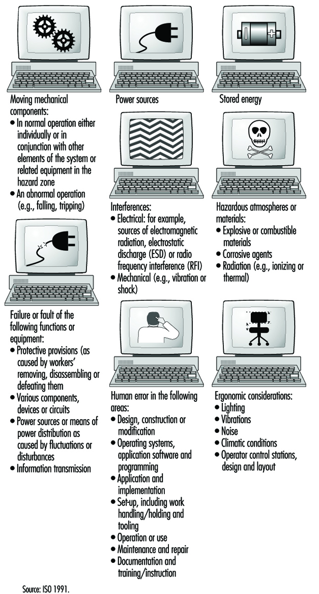
Human and System Errors
In general, hazards in a HAS can arise from the system itself, from its association with other equipment present in the physical environment, or from interactions of human personnel with the system. An accident is only one of the several outcomes of human-machine interactions that may emerge under hazardous conditions; near accidents and damage incidents are much more common (Zimolong and Duda 1992). The occurrence of an error can lead to one of these consequences: (1) the error remains unnoticed, (2) the system can compensate for the error, (3) the error leads to a machine breakdown and/or system stoppage or (4) the error leads to an accident.
Since not every human error that results in a critical incident will cause an actual accident, it is appropriate to distinguish further among outcome categories as follows: (1) an unsafe incident (i.e., any unintentional occurrence regardless whether it results in injury, damage or loss), (2) an accident (i.e., an unsafe event resulting in injury, damage or loss), (3) a damage incident (i.e., an unsafe event which results only in some kind of material damage), (4) a near accident or “near miss” (i.e., an unsafe event in which injury, damage or loss was fortuitously avoided by a narrow margin) and (5) the existence of accident potential (i.e., unsafe events which could have resulted in injury, damage, or loss, but, owing to circumstances, did not result in even a near accident).
One can distinguish three basic types of human error in a HAS:
- skill-based slips and lapses
- rule-based mistakes
- knowledge-based mistakes.
This taxonomy, devised by Reason (1990), is based on a modification of Rasmussen’s skill-rule-knowledge classification of human performance as described above. At the skill-based level, human performance is governed by stored patterns of pre-programmed instructions represented as analogue structures in a space-time domain. The rule-based level is applicable to tackling familiar problems in which solutions are governed by stored rules (called “productions”, since they are accessed, or produced, at need). These rules require certain diagnoses (or judgements) to be made, or certain remedial actions to be taken, given that certain conditions have arisen that demand an appropriate response. At this level, human errors are typically associated with the misclassification of situations, leading either to the application of the wrong rule or to the incorrect recall of consequent judgements or procedures. Knowledge-based errors occur in novel situations for which actions must be planned “on-line” (at a given moment), using conscious analytical processes and stored knowledge. Errors at this level arise from resource limitations and incomplete or incorrect knowledge.
The generic error-modelling systems (GEMS) proposed by Reason (1990), which attempts to locate the origins of the basic human error types, can be used to derive the overall taxonomy of human behaviour in a HAS. GEMS seeks to integrate two distinct areas of error research: (1) slips and lapses, in which actions deviate from current intention due to execution failures and/or storage failures and (2) mistakes, in which the actions may run according to plan, but the plan is inadequate to achieve its desired outcome.
Risk Assessment and Prevention in CIM
According to the ISO (1991), risk assessment in CIM should be performed so as to minimize all risks and to serve as a basis for determining safety objectives and measures in the development of programmes or plans both to create a safe working environment and to ensure the safety and health of personnel as well. For example, work hazards in manufacturing-based HAS environments can be characterized as follows: (1) the human operator may need to enter the danger zone during disturbance recovery, service and maintenance tasks, (2) the danger zone is difficult to determine, to perceive and to control, (3) the work may be monotonous and (4) the accidents occurring within computer-integrated manufacturing systems are often serious. Each identified hazard should be assessed for its risk, and appropriate safety measures should be determined and implemented to minimize that risk. Hazards should also be ascertained with respect to all of the following aspects of any given process: the single unit itself; the interaction between single units; the operating sections of the system; and the operation of the complete system for all intended operating modes and conditions, including conditions under which normal safeguarding means are suspended for such operations as programming, verification, troubleshooting, maintenance or repair.
The design phase of the ISO (1991) safety strategy for CIM includes:
- specification of the limits of system parameters
- application of a safety strategy
- identification of hazards
- assessment of the associated risks
- removal of the hazards or diminution of the risks as much as practicable.
The system safety specification should include:
- a description of system functions
- a system layout and/or model
- the results of a survey undertaken to investigate the interaction of different working processes and manual activities
- an analysis of process sequences, including manual interaction
- a description of the interfaces with conveyor or transport lines
- process flow charts
- foundation plans
- plans for supply and disposal devices
- determination of the space required for supply and disposal of material
- available accident records.
In accordance with the ISO (1991), all necessary requirements for ensuring a safe CIM system operation need to be considered in the design of systematic safety-planning procedures. This includes all protective measures to effectively reduce hazards and requires:
- integration of the human-machine interface
- early definition of the position of those working on the system (in time and space)
- early consideration of ways of cutting down on isolated work
- consideration of environmental aspects.
The safety planning procedure should address, among others, the following safety issues of CIM:
- Selection of the operating modes of the system. The control equipment should have provisions for at least the following operating modes:(1) normal or production mode (i.e., with all normal safeguards connected and operating), (2) operation with some of the normal safeguards suspended and (3) operation in which system or remote manual initiation of hazardous situations is prevented (e.g., in the case of local operation or of isolation of power to or mechanical blockage of hazardous conditions).
- Training, installation, commissioning and functional testing. When personnel are required to be in the hazard zone, the following safety measures should be provided in the control system: (1) hold to run, (2) enabling device, (3) reduced speed, (4) reduced power and (5) moveable emergency stop.
- Safety in system programming, maintenance and repair. During programming, only the programmer should be allowed in the safeguarded space. The system should have inspection and maintenance procedures in place to ensure continued intended operation of the system. The inspection and maintenance programme should take into account the recommendations of the system supplier and those of suppliers of various elements of the systems. It scarcely needs mentioning that personnel who perform maintenance or repairs on the system should be trained in the procedures necessary to perform the required tasks.
- Fault elimination. Where fault elimination is necessary from inside the safeguarded space, it should be performed after safe disconnection (or, if possible, after a lockout mechanism has been actuated). Additional measures against erroneous initiation of hazardous situations should be taken. Where hazards can occur during fault elimination at sections of the system or at the machines of adjoining systems or machines, these should also be taken out of operation and protected against unexpected starting. By means of instruction and warning signs, attention should be drawn to fault elimination in system components which cannot be observed completely.
System Disturbance Control
In many HAS installations utilized in the computer-integrated manufacturing area, human operators are typically needed for the purpose of controlling, programming, maintaining, pre-setting, servicing or troubleshooting tasks. Disturbances in the system lead to situations that make it necessary for workers to enter the hazardous areas. In this respect, it can be assumed that disturbances remain the most important reason for human interference in CIM, because the systems will more often than not be programmed from outside the restricted areas. One of the most important issues for CIM safety is to prevent disturbances, since most risks occur in the troubleshooting phase of the system. The avoidance of disturbances is the common aim as regards both safety and cost-effectiveness.
A disturbance in a CIM system is a state or function of a system that deviates from the planned or desired state. In addition to productivity, disturbances during the operation of a CIM have a direct effect on the safety of the people involved in operating the system. A Finnish study (Kuivanen 1990) showed that about one-half of the disturbances in automated manufacturing decrease the safety of the workers. The main causes for disturbances were errors in system design (34%), system component failures (31%), human error (20%) and external factors (15%). Most machine failures were caused by the control system, and, in the control system, most failures occurred in sensors. An effective way to increase the level of safety of CIM installations is to reduce the number of disturbances. Although human actions in disturbed systems prevent the occurrence of accidents in the HAS environment, they also contribute to them. For example, a study of accidents related to malfunctions of technical control systems showed that about one-third of the accident sequences included human intervention in the control loop of the disturbed system.
The main research issues in CIM disturbance prevention concern (1) major causes of disturbances, (2) unreliable components and functions, (3) the impact of disturbances on safety, (4) the impact of disturbances on the function of the system, (5) material damage and (6) repairs. The safety of HAS should be planned early at the system design stage, with due consideration of technology, people and organization, and be an integral part of the overall HAS technical planning process.
HAS Design: Future Challenges
To assure the fullest benefit of hybrid automated systems as discussed above, a much broader vision of system development, one which is based on integration of people, organization and technology, is needed. Three main types of system integration should be applied here:
- integration of people, by assuring effective communication between them
- human-computer integration, by designing suitable interfaces and interaction between people and computers
- technological integration, by assuring effective interfacing and interactions between machines.
The minimum design requirements for hybrid automated systems should include the following: (1) flexibility, (2) dynamic adaptation, (3) improved responsiveness, and (4) the need to motivate people and make better use of their skills, judgement and experience. The above also requires that HAS organizational structures, work practices and technologies be developed to allow people at all levels of the system to adapt their work strategies to the variety of systems control situations. Therefore, the organizations, work practices and technologies of HAS will have to be designed and developed as open systems (Kidd 1994).
An open hybrid automated system (OHAS) is a system that receives inputs from and sends outputs to its environment. The idea of an open system can be applied not only to system architectures and organizational structures, but also to work practices, human-computer interfaces, and the relationship between people and technologies: one may mention, for example, scheduling systems, control systems and decision support systems. An open system is also an adaptive one when it allows people a large degree of freedom to define the mode of operating the system. For example, in the area of advanced manufacturing, the requirements of an open hybrid automated system can be realized through the concept of human and computer-integrated manufacturing (HCIM). In this view, the design of technology should address the overall HCIM system architecture, including the following: (1) considerations of the network of groups, (2) the structure of each group, (3) the interaction between groups, (4) the nature of the supporting software and (5) technical communication and integration needs between supporting software modules.
The adaptive hybrid automated system, as opposed to the closed system, does not restrict what the human operators can do. The role of the designer of a HAS is to create a system that will satisfy the user’s personal preferences and allow its users to work in a way that they find most appropriate. A prerequisite for permitting user input is the development of an adaptive design methodology—that is, an OHAS that allows enabling, computer-supported technology for its implementation in the design process. The need to develop a methodology for adaptive design is one of the immediate requirements to realize the OHAS concept in practice. A new level of adaptive human supervisory control technology needs also to be developed. Such technology should allow the human operator to “see through” the otherwise invisible control system of HAS functioning—for example, by application of an interactive, high-speed video system at each point of system control and operation. Finally, a methodology for development of an intelligent and highly adaptive, computer-based support of human roles and human functioning in the hybrid automated systems is also very much needed.
Principles for the Design of Safe Control Systems
It is generally agreed that control systems must be safe during use. With this in mind, most modern control systems are designed as shown in figure 1.
Figure 1. General design of control systems
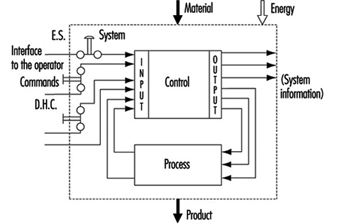
The simplest way to make a control system safe is to construct an impenetrable wall around it so as to prevent human access or interference into the danger zone. Such a system would be very safe, albeit impractical, since it would be impossible to gain access in order to perform most testing, repair and adjustment work. Because access to danger zones must be permitted under certain conditions, protective measures other than just walls, fences and the like are required to facilitate production, installation, servicing and maintenance.
Some of these protective measures can be partly or fully integrated into control systems, as follows:
- Movement can be stopped immediately should anybody enter the danger zone, by means of emergency stop (ES) buttons.
- Push-button controls permit movement only when the push-button is activated.
- Double-hand controls (DHC) permit movement only when both hands are engaged in depressing the two control elements (thus ensuring that hands are kept away from the danger zones).
These types of protective measures are activated by operators. However, because human beings often represent a weak point in applications, many functions, such as the following, are performed automatically:
- Movements of robot arms during the servicing or “teach-in” are very slow. Nonetheless, speed is continuously monitored. If, because of a control system failure, the speed of automatic robot arms were to increase unexpectedly during either the servicing or teach-in period, the monitoring system would activate and immediately terminate movement.
- A light barrier is provided to prevent access into a danger zone. If the light beam is interrupted, the machine will stop automatically.
Normal function of control systems is the most important precondition for production. If a production function is interrupted due to a control failure, it is at most inconvenient but not hazardous. If a safety-relevant function is not performed, it could result in lost production, equipment damage, injury or even death. Therefore, safety-relevant control system functions must be more reliable and safer than normal control system functions. According to European Council Directive 89/392/EEC (Machine Guidelines), control systems must be designed and constructed so that they are safe and reliable.
Controls consist of a number of components connected together so as to perform one or more functions. Controls are subdivided into channels. A channel is the part of a control that performs a specific function (e.g., start, stop, emergency stop). Physically, the channel is created by a string of components (transistors, diodes, relays, gates, etc.) through which, from one component to the next, (mostly electrical) information representing that function is transferred from input to output.
In designing control channels for safety-relevant functions (those functions which involve humans), the following requirements must be fulfilled:
- Components used in control channels with safety-relevant functions must be able to withstand the rigours of normal use. Generally, they must be sufficiently reliable.
- Errors in the logic must not cause dangerous situations. Generally, the safety-relevant channel is to be sufficiently failure proof.
- External influences (factors) should not lead to temporary or permanent failures in safety-relevant channels.
Reliability
Reliability is the ability of a control channel or component to perform a required function under specified conditions for a given period of time without failing. (Probability for specific components or control channels can be calculated using suitable methods.) Reliability must always be specified for a specific time value. Generally, reliability can be expressed by the formula in figure 2.
Figure 2. Reliability formula
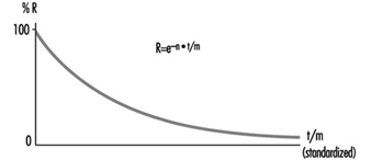
Reliability of complex systems
Systems are built from components. If the reliabilities of the components are known, the reliability of the system as a whole can be calculated. In such cases, the following apply:
Serial systems
The total reliability Rtot of a serial system consisting of N components of the same reliability RC is calculated as in figure 3.
Figure 3. Reliability graph of serially connected components
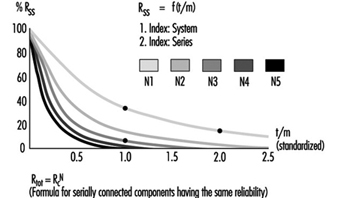
The total reliability is lower than the reliability of the least reliable component. As the number of serially connected components increases, the total reliability of the chain falls significantly.
Parallel systems
The total reliability Rtot of a parallel system consisting of N components of the same reliability RC is calculated as in figure 4.
Figure 4. Reliability graph of parallel connected components
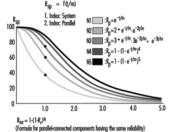
Total reliability can be improved significantly through the parallel connection of two or more components.
Figure 5 illustrates a practical example. Note that the circuitry will switch off the motor more reliably. Even if relay A or B fails to open its contact, the motor will still be switched off.
Figure 5. Practical example of figure 4
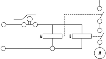
To calculate the total reliability of a channel is simple if all necessary component reliabilities are known and available. In the case of complex components (integrated circuits, microprocessors, etc.) the calculation of the total reliability is difficult or impossible if the necessary information is not published by the manufacturer.
Safety
When professionals speak about safety and call for safe machines, they mean the safety of the entire machine or system. This safety is, however, too general, and not precisely enough defined for the designer of controls. The following definition of safety may be practical and usable to designers of control circuitry: Safety is the ability of a control system to perform the required function within prescribed limits, for a given duration, even when anticipated fault(s) occur. Consequently, it must be clarified during the design how “safe” the safety-related channel must be. (The designer can develop a channel that is safe against first failure, against any one failure, against two failures, etc.) Furthermore, a channel that performs a function which is used to prevent accidents may be essentially reliable, but it does not have to be inevitably safe against failures. This may be best explained by the following examples:
Example 1
The example illustrated in figure 6 is a safety-relevant control channel performing the required safety function. The first component may be a switch that monitors, for example, the position of an access door to a dangerous area. The last component is a motor which drives moving mechanical parts within the danger area.
Figure 6. A safety-relevant control channel performing the required safety function
The required safety function in this case is a dual one: If the door is closed, the motor may run. If the door is open, the motor must be switched off. Knowing reliabilities R1 to R6, it is possible to calculate reliability Rtot. Designers should use reliable components in order to maintain sufficiently high reliability of the whole control system (i.e., the probability that this function may still be performed in, say, even 20 years should be accounted for in the design). As a result, designers must fulfil two tasks: (1) the circuitry must perform the required function, and (2) the reliability of the components and of the whole control channel must be adequate.
The following question should now be asked: Will the aforementioned channel perform the required safety functions even if a failure occurs in the system (e.g., if a relay contact sticks or a component malfunctions)? The answer is “No”. The reason is that a single control channel consisting only of serially connected components and working with static signals is not safe against one failure. The channel can have only a certain reliability, which guarantees the probability that the function will be carried out. In such situations, safety is always meant as failure related.
Example 2
If a control channel is to be both reliable and safe, the design must be modified as in figure 7. The example illustrated is a safety-relevant control channel consisting of two fully separated subchannels.
Figure 7. A safety-relevant control channel with two fully separate subchannels
This design is safe against the first failure (and possible further failures in the same subchannel), but is not safe against two failures which may occur in two different subchannels (simultaneously or at different times) because there is no failure detection circuit. Consequently, initially both subchannels work with a high reliability (see parallel system), but after the first failure only one subchannel will work, and reliability decreases. Should a second failure occur in the subchannel still working, both will have then failed, and the safety function will no longer be performed.
Example 3
The example illustrated in figure 8 is a safety-relevant control channel consisting of two fully separate subchannels which monitor each other.
Figure 8. A safety-relevant control channel with two fully separate subchannels which monitor each other
Such a design is failure safe because after any failure, only one subchannel will be non-functional, while the other subchannel remains available and will perform the safety function. Moreover, the design has a failure detection circuit. If, due to a failure, both subchannels fail to work in the same way, this condition will be detected by “exclusive or” circuitry, with the result that the machine will be automatically switched off. This is one of the best ways of designing machine controls—designing safety-relevant subchannels. They are safe against one failure and at the same time provide enough reliability so that the chances that two failures will occur simultaneously is minuscule.
Redundancy
It is apparent that there are various methods by which a designer may improve reliability and/or safety (against failure). The previous examples illustrate how a function (i.e., door closed, motor may run; door opened, motor must be stopped) can be realized by various solutions. Some methods are very simple (one subchannel) and others more complicated (two subchannels with mutual supervising). (See figure 9.)
Figure 9. Reliability of redundant systems with or without failure detection
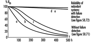
There is a certain redundancy in the complex circuitry and/or components in comparison with the simple ones. Redundancy can be defined as follows: (1) Redundancy is the presence of more means (components, channels, higher safety factors, additional tests and so on) than are really necessary for the simple fulfilling of the desired function; (2) redundancy obviously does not “improve” the function, which is performed anyway. Redundancy only improves reliability and/or safety.
Some safety professionals believe that redundancy is only the doubling or tripling, and so on, of the system. This is a very limited interpretation, as redundancy may be interpreted much more broadly and flexibly. Redundancy may be not only included in the hardware; it may be included in the software too. Improving the safety factor (e.g., a stronger rope instead of a weaker rope) may also be considered as a form of redundancy.
Entropy
Entropy, a term found mostly in thermodynamics and astronomy, may be defined as follows: Everything tends towards decay. Therefore, it is absolutely certain that all components, subsystems or systems, independently of the technology in use, will fail sometime. This means that there are no 100% reliable and/or safe systems, subsystems or components. All of them are merely more or less reliable and safe, depending on the structure’s complexity. The failures which inevitably occur earlier or later demonstrate the action of entropy.
The only means available to designers to counter entropy is redundancy, which is achieved by (a) introducing more reliability into the components and (b) providing more safety throughout the circuit architecture. Only by sufficiently raising the probability that the required function will be performed for the required period of time, can designers in some degree defend against entropy.
Risk Assessment
The greater the potential risk, the higher the reliability and/or safety (against failures) that is required (and vice versa). This is illustrated by the following two cases:
Case 1
Access to the mould tool fixed in an injection moulding machine is safeguarded by a door. If the door is closed, the machine may work, and if the door is opened, all dangerous movements have to be stopped. Under no circumstances (even in case of failure in the safety-related channel) may any movements, especially those which operate the tool, occur.
Case 2
Access to an automatically controlled assembly line that assembles small plastic components under pneumatic pressure is guarded by a door. If this door is opened, the line will have to be stopped.
In Case 1, if the door-supervising control system should fail, a serious injury may occur if the tool is closed unexpectedly. In Case 2, only slight injury or insignificant harm may result if the door-supervising control system fails.
It is obvious that in the first case much more redundancy must be introduced to attain the reliability and/or safety (against failure) required to protect against extreme high risk. In fact, according to European Standard EN 201, the supervising control system of the injection moulding machine door has to have three channels; two of which are electrical and mutually supervised and one of which is mostly equipped with hydraulics and testing circuits. All these three supervising functions relate to the same door.
Conversely, in applications like that described in Case 2, a single channel activated by a switch with positive action is appropriate to the risk.
Control Categories
Because all of the above considerations are generally based on information theory and consequently are valid for all technologies, it does not matter whether the control system is based on electronic, electro-mechanical, mechanical, hydraulic or pneumatic components (or a mixture of them), or on some other technology. The inventiveness of the designer on the one hand and economic questions on the other hand are the primary factors affecting a nearly endless number of solutions as to how to realize safety-relevant channels.
To prevent confusion, it is practical to set certain sorting criteria. The most typical channel structures used in machine controls for performing safety-related functions are categorized according to:
- reliability
- behaviour in case of failure
- failure-disclosing time.
Their combinations (not all possible combinations are shown) are illustrated in table 1.
Table 1. Some possible combinations of circuit structures in machine controls for safety-related functions
|
Criteria (Questions) |
Basic strategy |
|||||
|
By raising the reliability (is the occurrence of failure shifted to the possibly far future?) |
By suitable circuit structure (architecture) failure will be at least detected (Cat. 2) or failure effect on the channel will be eliminated (Cat. 3) or failure will be disclosed immediately (Cat. 4) |
|||||
|
Categories |
||||||
|
This solution is basically wrong |
B |
1 |
2 |
3 |
4 |
|
|
Can the circuit components with stand the expected influences; are they constructed according to state of the art? |
No |
Yes |
Yes |
Yes |
Yes |
Yes |
|
Have well tried components and/or methods been used? |
No |
No |
Yes |
Yes |
Yes |
Yes |
|
Can a failure be detected automatically? |
No |
No |
No |
Yes |
Yes |
Yes |
|
Does a failure prevent the performing of the safety-related function? |
Yes |
Yes |
Yes |
Yes |
No |
No |
|
When will the failure be detected? |
Never |
Never |
Never |
Early (latest at the end of interval that is not longer than one machine cycle) |
Immediately (when the signal loses dynamical |
|
|
In consumer products |
To be used in machines |
|||||
The category applicable for a specific machine and its safety-related control system is mostly specified in the new European standards (EN), unless the national authority, the user and the manufacturer mutually agree that another category should be applied. The designer then develops a control system which fulfils the requirements. For example, considerations governing the design of a control channel may include the following:
- The components have to withstand the expected influences. (YES/NO)
- Their construction should be according to state-of-the-art standards. (YES/NO)
- Well-tried components and methods are used. (YES/NO)
- Failure must be detected. (YES/NO)
- Will the safety function be performed even in case of failure? (YES/NO)
- When will the failure be detected? (NEVER, EARLY, IMMEDIATELY)
This process is reversible. Using the same questions, one can decided which category an existing, previously developed control channel belongs to.
Category examples
Category B
The control channel components primarily used in consumer wares have to withstand the expected influences and be designed according to state of the art. A well-designed switch may serve as an example.
Category 1
The use of well-tried components and methods is typical for Category 1. A Category 1 example is a switch with positive action (i.e., requires forced opening of contacts). This switch is designed with robust parts and is activated by relatively high forces, thus reaching extremely high reliability only in contact opening. In spite of sticking or even welded contacts, these switches will open. (Note: Components such as transistors and diodes are not considered as being well-tried components.) Figure 10 will serve as an illustration of a Category 1 control.
Figure 10. A switch with a positive action
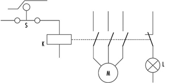
This channel uses switch S with positive action. The contactor K is supervised by the light L. The operator is advised that the normally open (NO) contacts stick by means of indication light L. The contactor K has forced guided contacts. (Note: Relays or contactors with forced guidance of contacts have, in comparison with usual relays or contactors, a special cage made from insulating material so that if normally closed (NC) contacts are closed, all NO contacts have to be opened, and vice versa. This means that by use of NC contacts a check may be made to determine that the working contacts are not sticking or welded together.)
Category 2
Category 2 provides for automatic detection of failures. Automatic failure detection has to be generated before each dangerous movement. Only if the test is positive may the movement be performed; otherwise the machine will be stopped. Automatic failure detection systems are used for light barriers to prove that they are still working. The principle is illustrated in figure 1.
Figure 11. Circuit including a failure detector
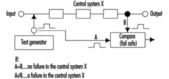
This control system is tested regularly (or occasionally) by injecting an impulse to the input. In a properly working system this impulse will then be transferred to the output and compared to an impulse from a test generator. When both impulses are present, the system obviously works. Otherwise, if there is no output impulse, the system has failed.
Category 3
Circuitry has been previously described under Example 3 in the Safety section of this article, figure 8.
The requirement—that is, automatic failure detection and the ability to perform the safety function even if one failure has occurred anywhere—can be fulfilled by two-channel control structures and by mutual supervising of the two channels.
For machine controls only, the dangerous failures have to be investigated. It should be noted that there are two kinds of failure:
- Non-dangerous failures are those that, after their occurrence, cause a “safe state” of the machine by providing for switching off the motor.
- Dangerous failures are those that, after their occurrence, cause an “unsafe state” of the machine, as the motor cannot be switched off or the motor starts to move unexpectedly.
Category 4
Category 4 typically provides for the application of a dynamic, continuously changing signal on the input. The presence of a dynamic signal on the output means running (“1”), and the absence of a dynamic signal means stop (“0”).
For such circuitry it is typical that after failure of any component the dynamic signal will no longer be available on the output. (Note: The static potential on the output is irrelevant.) Such circuits may be called “fail-safe”. All failures will be disclosed immediately, not after the first change (as in Category 3 circuits).
Further comments on control categories
Table 1 has been developed for usual machine controls and shows the basic circuit structures only; according to the machine directive it should be calculated on the assumption that only one failure will occur in one machine cycle. This is why the safety function does not have to be performed in the case of two coincident failures. It is assumed that a failure will be detected within one machine cycle. The machine will be stopped and then repaired. The control system then starts again, fully operable, without failures.
The first intent of the designer should be not to permit “standing” failures, which would not be detected during one cycle as they might later be combined with newly occurring failure(s) (failure cumulation). Such combinations (a standing failure and a new failure) can cause a malfunction of even Category 3 circuitry.
In spite of these tactics, it is possible that two independent failures will occur at the same time within the same machine cycle. It is only very improbable, especially if highly reliable components have been used. For very high-risk applications, three or more subchannels should be used. This philosophy is based on the fact that the mean time between failures is much longer than the machine cycle.
This does not mean, however, that the table cannot be further expanded. Table 1 is basically and structurally very similar to the Table 2 used in EN 954-1. However, it does not try to include too many sorting criteria. The requirements are defined according to the rigorous laws of logic, so that only clear answers (YES or NO) can be expected. This allows a more exact assessment, sorting and classification of submitted circuitry (safety-related channels) and, last but not least, significant improvement of assessment reproducibility.
It would be ideal if risks could be classified in various risk levels and then a definite link established between risk levels and categories, with this all independent of the technology in use. However, this is not fully possible. Early after creating categories it became clear that even given the same technology, various questions were not sufficiently answered. Which is better: a very reliable and well-designed component of Category 1, or a system fulfilling the requirements of Category 3 with poor reliability?
To explain this dilemma one must differentiate between two qualities: reliability and safety (against failures). They are not comparable, as both these qualities have different features:
- The component with highest reliability has the unpleasant feature that in the event of failure (even if highly improbable) the function will cease to perform.
- Category 3 systems, where even in case of one failure the function will be performed, are not safe against two failures at the same time (what may be important is whether sufficiently reliable components have been used).
Considering the above, it may be that the best solution (from the high-risk point of view) is to use highly reliable components and configure them so that the circuitry is safe against at least one failure (preferably more). It is clear that such a solution is not the most economical. In practice, the optimization process is mostly the consequence of all these influences and considerations.
Experience with practical use of the categories shows that it is rarely possible to design a control system that can utilize only one category throughout. Combination of two or even three parts, each of a different category, is typical, as illustrated in the following example:
Many safety light barriers are designed in Category 4, wherein one channel works with a dynamic signal. At the end of this system there usually are two mutually supervised subchannels which work with static signals. (This fulfils the requirements for Category 3.)
According to EN 50100, such light barriers are classified as Type 4 electro-sensitive protective devices, although they are composed of two parts. Unfortunately, there is no agreement how to denominate control systems consisting of two or more parts, each part of another category.
Programmable Electronic Systems (PESs)
The principles used to create table 1 can, with certain restrictions of course, be generally appled to PESs too.
PES-only system
In using PESs for control, the information is transferred from the sensor to the activator through a large number of components. Beyond that, it even passes “through” software. (See figure 12).
Figure 12. A PES system circuit
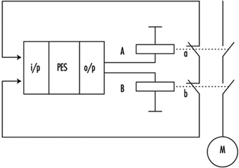
Although modern PESs are very reliable, the reliability is not as high as may be required for processing safety functions. Beyond that, the usual PES systems are not safe enough, since they will not perform the safety-related function in case of a failure. Therefore, using PESs for processing of safety functions without any additional measures is not permitted.
Very low-risk applications: Systems with one PES and additional measures
When using a single PES for control, the system consists of the following primary parts:
Input part
The reliability of a sensor and input of a PES can be improved by doubling them. Such a double-system input configuration can be further supervised by software to check if both subsystems are delivering the same information. Thus the failures in the input part can be detected. This is nearly the same philosophy as required for Category 3. However, because the supervising is done by software and only once, this may be denominated as 3- (or not as reliable as 3).
Middle part
Although this part cannot be well doubled, it can be tested. Upon switching on (or during operation), a check of the entire instruction set can be performed. At the same intervals, the memory can also be checked by suitable bit patterns. If such checks are conducted without failure, both parts, CPU and memory, are obviously working properly. The middle part has certain features typical of Category 4 (dynamic signal) and others typical of Category 2 (testing performed regularly at suitable intervals). The problem is that these tests, in spite of their extensiveness, cannot be really complete, as the one-PES system inherently does not allow them.
Output part
Similar to an input, the output (including activators) can also be doubled. Both subsystems can be supervised with respect to the same result. Failures will be detected and the safety function will be performed. However, there are the same weak points as in the input part. Consequently, Category 3 is chosen in this case.
In figure 13 the same function is brought to relays A and B. The control contacts a and b, then informs two input systems whether both relays are doing the same work (unless a failure in one of the channels has occurred). Supervising is done again by software.
Figure 13. A PES circuit with a failure-detection system
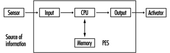
The whole system can be described as Category 3-/4/2/3- if properly and extensively done. Nevertheless, the weak points of such systems as above described cannot be fully eliminated. In fact, improved one PESs are actually used for safety-related functions only where the risks are rather low (Hölscher and Rader 1984).
Low- and medium-risk applications with one PES
Today almost every machine is equipped with a PES control unit. To solve the problem of insufficient reliability and usually insufficient safety against failure, the following design methods are commonly used:
- In relatively simple machines such as lifts, the functions are divided into two groups: (1) the functions that are not related to safety are processed by the PES; (2) the safety-related functions are combined in one chain (safety circuit) and processed outside of the PES (see figure 14).
Figure 14. State of the art for stop category 0
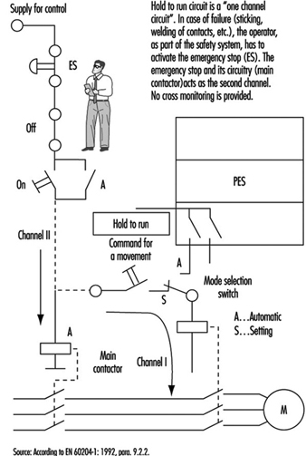
- The method given above is not suitable for more complex machines. One reason is that such solutions usually are not safe enough. For medium-risk applications, solutions should fulfil the requirements for category 3. General ideas of how such designs may look are presented in figure 15 and figure 16.
Figure 15. State of the art for stop category 1
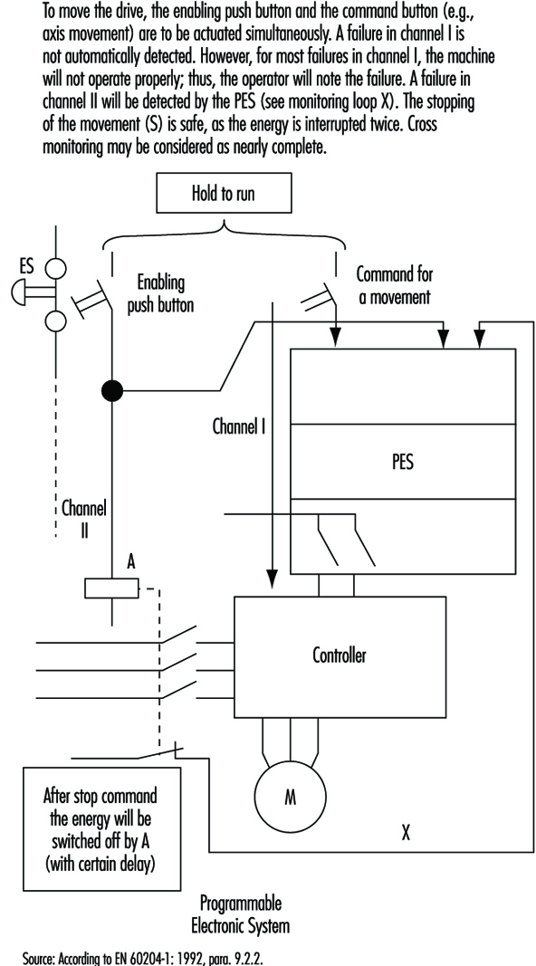
Figure 16. State of the art for stop category 2
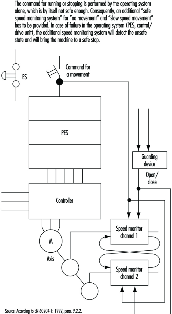
High-risk applications: systems with two (or more) PESs
Aside from complexity and expense, there are no other factors that would prevent designers from using fully doubled PES systems such as Siemens Simatic S5-115F, 3B6 Typ CAR-MIL and so on. These typically include two identical PESs with homogenous software, and assume the use of “well-tried” PESs and “well-tried” compilers (a well-tried PES or compiler can be considered one that in many practical applications over 3 or more years has shown that systematic failures have been obviously eliminated). Although these doubled PES systems do not have the weak points of single-PES systems, it does not mean that doubled PES systems solve all problems. (See figure 17).
Figure 17. Sophisticated system with two PESs
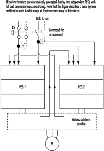
Systematic Failures
Systematic failures may result from errors in specifications, design and other causes, and may be present in hardware as well as in software. Double-PES systems are suitable for use in safety-related applications. Such configurations allow the detection of random hardware failures. By means of hardware diversity such as the use of two different types, or products of two different manufacturers, systematic hardware failures could be disclosed (it is highly unlikely that an identical hardware systematic failure would occur in both PES).
Software
Software is a new element in safety considerations. Software is either correct or incorrect (with respect to failures). Once correct, software cannot become instantly incorrect (as compared to hardware). The aims are to eradicate all errors in the software or to at least identify them.
There are various ways of achieving this goal. One is the verification of the program (a second person attempts to discover the errors in a subsequent test). Another possibility is diversity of the software, wherein two different programs, written by two programmers, address the same problem. If the results are identical (within certain limits), it can be assumed that both program sections are correct. If the results are different, it is presumed that errors are present. (N.B., The architecture of the hardware naturally must also be considered.)
Summary
When using PESs, generally the same following basic considerations are to be taken in account (as described in the previous sections).
- One control system without any redundancy may be allocated to Category B. One control system with additional measures may be Category 1 or even higher, but not higher than 2.
- A two-part control system with mutual comparison of results may be allocated to Category 3. A two-part control system with mutual comparison of results and more or less diversity may be allocated to Category 3 and is suitable for higher-risk applications.
A new factor is that for the system with a PES, even software should be evaluated from the correctness point of view. Software, if correct, is 100% reliable. At this stage of technological development, the best possible and known technical solutions will probably not be used, since the limiting factors are still economic. Furthermore, various groups of experts are continuing to develop the standards for safety applications of PESs (e.g., EC, EWICS). Although there are various standards already available (VDE0801, IEC65A and so on), this matter is so broad and complex that none of them may be considered as final.
Safety Principles for CNC Machine Tools
Whenever simple and conventional production equipment, such as machine tools, is automated, the result is complex technical systems as well as new hazards. This automation is achieved through the use of computer numeric control (CNC) systems on machine tools, called CNC machine tools (e.g., milling machines, machining centres, drills and grinders). In order to be able to identify the potential hazards inherent in automatic tools, the various operating modes of each system should be analysed. Previously conducted analyses indicate that a differentiation should be made between two types of operation: normal operation and special operation.
It is often impossible to prescribe the safety requirements for CNC machine tools in the shape of specific measures. This may be because there are too few regulations and standards specific to the equipment which provide concrete solutions. Safety requirements can be determined only if the possible hazards are identified systematically by conducting a hazard analysis, particularly if these complex technical systems are fitted with freely programmable control systems (as with CNC machine tools).
In the case of newly developed CNC machine tools, the manufacturer is obliged to carry out a hazard analysis on the equipment in order to identify whatever dangers may be present and to show by means of constructive solutions that all dangers to persons, in all of the different operating modes, are eliminated. All the hazards identified must be subjected to a risk assessment wherein each risk of an event is dependent on the scope of damage and the frequency with which it may occur. The hazard to be assessed is also given a risk category (minimized, normal, increased). Wherever the risk cannot be accepted on the basis of the risk assessment, solutions (safety measures) must be found. The purpose of these solutions is to reduce the frequency of occurrence and the scope of damage of an unplanned and potentially hazardous incident (an “event”).
The approaches to solutions for normal and increased risks are to be found in indirect and direct safety technology; for minimized risks, they are to be found in referral safety technology:
- Direct safety technology. Care is taken at the design stage to eliminate any hazards (e.g., the elimination of shearing and trapping points).
- Indirect safety technology. The hazard remains. However, the addition of technical arrangements prevents the hazard from turning into an event (e.g., such arrangements may include the prevention of access to dangerous moving parts by means of physical safety hoods, the provision of safety devices which turn power off, shielding from flying parts using safety guards, etc.).
- Referral safety technology. This applies only to residual hazards and minimized risks—that is, hazards which can lead to an event as a result of human factors. The occurrence of such an event can be prevented by appropriate behaviour on the part of the person concerned (e.g., instructions on behaviour in the operating and maintenance manuals, personnel training, etc.).
International Safety Requirements
The EC Machinery Directive (89/392/EEC) of 1989 lays down the principal safety and health requirements for machines. (According to the Machinery Directive, a machine is considered to be the sum total of interlinked parts or devices, of which at least one can move and correspondingly has a function.) In addition, individual standards are created by international standardization bodies to illustrate possible solutions (e.g., by attending to fundamental safety aspects, or by examining electrical equipment fitted to industrial machinery). The aim of these standards is to specify protection goals. These international safety requirements give manufacturers the necessary legal basis to specify these requirements in the above-mentioned hazard analyses and risk assessments.
Operating Modes
When using machine tools, a differentiation is made between normal operation and special operation. Statistics and investigations indicate that the majority of incidents and accidents do not take place in normal operation (i.e., during the automatic fulfilment of the assignment concerned). With these types of machines and installations, there is an emphasis on special modes of operations such as commissioning, setting up, programming, test runs, checks, troubleshooting or maintenance. In these operating modes, persons are usually in a danger zone. The safety concept must protect personnel from harmful events in these types of situations.
Normal operation
The following applies to automatic machines when carrying out normal operation: (1) the machine fulfils the assignment for which it was designed and constructed without any further intervention by the operator, and (2) applied to a simple turning machine, this means that a workpiece is turned to the correct shape and chips are produced. If the workpiece is changed manually, changing the workpiece is a special mode of operation.
Special modes of operation
Special modes of operation are working processes which allow normal operation. Under this heading, for example, one would include workpiece or tool changes, rectifying a fault in a production process, rectifying a machine fault, setting up, programming, test runs, cleaning and maintenance. In normal operation, automatic systems fulfil their assignments independently. From the viewpoint of working safety, however, automatic normal operation becomes critical when the operator has to intervene working processes. Under no circumstances may the persons intervening in such processes be exposed to hazards.
Personnel
Consideration must be given to the persons working in the various modes of operation as well as to third parties when safeguarding machine tools. Third parties also include those indirectly concerned with the machine, such as supervisors, inspectors, assistants for transporting material and dismantling work, visitors and others.
Demands and Safety Measures for Machine Accessories
Interventions for jobs in special operation modes mean that special accessories have to be used to assure work can be conducted safely. The first type of accessories include equipment and items used to intervene in the automatic process without the operator’s having to access a hazardous zone. This type of accessory includes (1) chip hooks and tongs which have been so designed that chips in the machining area can be removed or pulled away through the apertures provided in the safety guards, and (2) workpiece clamping devices with which the production material can be manually inserted into or removed from an automatic cycle
Various special modes of operation—for example, remedial work or maintenance work—make it necessary for personnel to intervene in a system. In these cases, too, there is a whole range of machine accessories designed to increase working safety—for example, devices to handle heavy grinding wheels when the latter are changed on grinders, as well as special crane slings for dismantling or erecting heavy components when machines are overhauled. These devices are the second type of machine accessory for increasing safety during work in special operations. Special operation control systems can also be considered to represent a second type of machine accessory. Particular activities can be carried out safely with such accessories—for example, a device can be set up in the machine axes when feed movements are necessary with the safety guards open.
These special operation control systems must satisfy particular safety requirements. For example, they must ensure that only the movement requested is carried out in the way requested and only for as long as requested. The special operation control system must therefore be designed in such a way as to prevent any faulty action from turning into hazardous movements or states.
Equipment which increases the degree of automation of an installation can be considered to be a third type of machine accessory for increasing working safety. Actions which were previously carried out manually are done automatically by the machine in normal operation, such as equipment including portal loaders, which change the workpieces on machine tools automatically. The safeguarding of automatic normal operation causes few problems because the intervention of an operator in the course of events is unnecessary and because possible interventions can be prevented by safety devices.
Requirements and Safety Measures for the Automation of Machine Tools
Unfortunately, automation has not led to the elimination of accidents in production plants. Investigations simply show a shift in the occurrence of accidents from normal to special operation, primarily due to the automation of normal operation so that interventions in the course of production are no longer necessary and personnel are thus no longer exposed to danger. On the other hand, highly automatic machines are complex systems which are difficult to assess when faults occur. Even the specialists employed to rectify faults are not always able to do so without incurring accidents. The amount of software needed to operate increasingly complex machines is growing in volume and complexity, with the result that an increasing number of electrical and commissioning engineers suffer accidents. There is no such thing as flawless software, and changes in software often lead to changes elsewhere which were neither expected nor wanted. In order to prevent safety from being affected, hazardous faulty behaviour caused by external influence and component failures must not be possible. This condition can be fulfilled only if the safety circuit is designed as simply as possible and is separate from the rest of the controls. The elements or sub-assemblies used in the safety circuit must also be fail-safe.
It is the task of the designer to develop designs that satisfy safety requirements. The designer cannot avoid having to consider the necessary working procedures, including the special modes of operation, with great care. Analyses must be made to determine which safe work procedures are necessary, and the operating personnel must become familiar with them. In the majority of cases, a control system for special operation will be necessary. The control system usually observes or regulates a movement, while at the same time, no other movement must be initiated (as no other movement is needed for this work, and thus none is expected by the operator). The control system does not necessarily have to carry out the same assignments in the various modes of special operation.
Requirements and Safety Measures in Normal and Special Modes of Operation
Normal operation
The specification of safety goals should not impede technical progress because adapted solutions can be selected. The use of CNC machine tools makes maximum demands on hazard analysis, risk assessment and safety concepts. The following describes several safety goals and possible solutions in greater detail.
Safety goal
- Manual or physical access to hazardous areas during automatic movements must be prevented.
Possible solutions
- Prevent manual or physical access into danger zones by means of mechanical barriers.
- Provide safety devices that respond when approached (light barriers, safety mats) and switch off machinery safely during interventions or entry.
- Allow manual or physical access to machinery (or its vicinity) only when the entire system is in a safe state (e.g., by using interlocking devices with closure mechanisms on the access doors).
Safety goal
- The possibility of any persons being injured as a result of the release of energy (flying parts or beams of energy) should be eliminated.
Possible solution
- Prevent the release of energy from the danger zone—for example, by a correspondingly dimensioned safety hood.
Special operation
The interfaces between normal operation and special operation (e.g., door interlocking devices, light barriers, safety mats) are necessary to enable the safety control system to recognize automatically the presence of personnel. The following describes certain special operation modes (e.g., setting up, programming) on CNC machine tools which require movements that must be assessed directly at the site of operation.
Safety goals
- Movements must take place only in such a way that they cannot be a hazard for the persons concerned. Such movements must be executed only in the scheduled style and speed and continued only as long as instructed.
- They are to be attempted only if it can be guaranteed that no parts of the human body are in the danger zone.
Possible solution
- Install special operating control systems which permit only controllable and manageable movements using finger-tip control via “acknowledge-type” push buttons. The speed of movements is thus safely reduced (provided that energy has been reduced by means of an isolation transformer or similar monitoring equipment).
Demands on Safety Control Systems
One of the features of a safety control system must be that the safety function is guaranteed to work whenever any faults arise so as to direct processes from a hazardous state to a safe state.
Safety goals
- A fault in the safety control system must not trigger off a dangerous state.
- A fault in the safety control system must be identified (immediately or at intervals).
Possible solutions
- Put in place a redundant and diverse layout of electro-mechanical control systems, including test circuits.
- Put in place a redundant and diverse set-up of microprocessor control systems developed by different teams. This approach is considered to be state of the art, for example, in the case of safety light barriers.
Conclusion
It is apparent that the increasing trend in accidents in normal and special modes of operation cannot be halted without a clear and unmistakable safety concept. This fact must be taken into account in the preparation of safety regulations and guidelines. New guidelines in the shape of safety goals are necessary in order to allow advanced solutions. This objective enables designers to choose the optimum solution for a specific case while at the same time demonstrating the safety features of their machines in a fairly simple way by describing a solution to each safety goal. This solution can then be compared with other existing and accepted solutions, and if it is better or at least of equal value, a new solution can then be chosen. In this way, progress is not hampered by narrowly formulated regulations.
Main Features of the EEC Machinery Directive
The Council Directive of 14 June 1989 on the approximation of the laws of the Member States relating machinery (89/392/EEC) applies to each individual state.
- Each individual state must integrate the directive in its legislation.
- Valid from 1 January 1993.
- Requires that all manufacturers adhere to the state of the art.
- The manufacturer must produce a technical construction file which contains full information on all fundamental aspects of safety and health care.
- The manufacturer must issue the declaration of conformity and the CE marking of the machines.
- Failure to place a complete technical documentation at the disposal of a state supervisory centre is considered to represent the non-fulfilment of the machine guidelines. A pan-EEC sales prohibition may be the consequence.
Safety Goals for the Construction and Use of CNC Machine Tools
1. Lathes
1.1 Normal mode of operation
1.1.1 The work area is to be safeguarded so that it is impossible to reach or step into the danger zones of automatic movements, either intentionally or unintentionally.
1.1.2 The tool magazine is to be safeguarded so that it is impossible to reach or step into the danger zones of automatic movements, either intentionally or unintentionally.
1.1.3 The workpiece magazine is to be safeguarded so that it is impossible to reach or step into the danger zones of automatic movements, either intentionally or unintentionally.
1.1.4 Chip removal must not result in personal injury due to the chips or moving parts of the machine.
1.1.5 Personal injuries resulting from reaching into drive systems must be prevented.
1.1.6 The possibility of reaching into the danger zones of moving chip conveyors must be prevented.
1.1.7 No personal injury to operators or third persons must result from flying workpieces or parts thereof.
For example, this can occur
- due to insufficient clamping
- due to inadmissible cutting force
- due to inadmissible rotation speed
- due to collision with the tool or machine parts
- due to workpiece breakage
- due to defective clamping fixtures
- due to power failure
1.1.8 No personal injury must result from flying workpiece clamping fixtures.
1.1.9 No personal injury must result from flying chips.
1.1.10 No personal injury must result from flying tools or parts thereof.
For example, this can occur
- due to material defects
- due to inadmissible cutting force
- due to a collision with the workpiece or a machine part
- due to inadequate clamping or tightening
1.2 Special modes of operation
1.2.1 Workpiece changing.
1.2.1.1 Workpiece clamping must be done in such a way that no parts of the body can become trapped between closing clamping fixtures and workpiece or between the advancing sleeve tip and workpiece.
1.2.1.2 The starting of a drive (spindles, axes, sleeves, turret heads or chip conveyors) as a consequence of a defective command or invalid command must be prevented.
1.2.1.3 It must be possible to manipulate the workpiece manually or with tools without danger.
1.2.2 Tool changing in tool holder or tool turret head.
1.2.2.1 Danger resulting from the defective behaviour of the system or due to entering an invalid command must be prevented.
1.2.3 Tool changing in the tool magazine.
1.2.3.1 Movements in the tool magazine resulting from a defective or invalid command must be prevented during tool changing.
1.2.3.2 It must not be possible to reach into other moving machine parts from the tool loading station.
1.2.3.3 It must not be possible to reach into danger zones on the further movement of the tool magazine or during the search. If taking place with the guards for normal operation mode removed, these movements may only be of the designated kind and only be carried out during the period of time ordered and only when it can be ensured that no parts of the body are in these danger zones.
1.2.4 Measurement check.
1.2.4.1 Reaching into the work area must only be possible after all movements have been brought to a standstill.
1.2.4.2 The starting of a drive resulting from a defective command or invalid command input must be prevented.
1.2.5 Set-up.
1.2.5.1 If movements are executed during set-up with the guards for normal mode of operation removed, then the operator must be safeguarded by another means.
1.2.5.2 No dangerous movements or changes of movements must be initiated as a result of a defective command or invalid command input.
1.2.6 Programming.
1.2.6.1 No movements may be initiated during programming which endanger a person in the work area.
1.2.7 Production fault.
1.2.7.1 The starting of a drive resulting from a defective command on invalid command input setpoint must be prevented.
1.2.7.2 No dangerous movements or situations are to be initiated by the movement or removal of the workpiece or waste.
1.2.7.3 Where movements have to take place with the guards for the normal mode of operation removed, these movements may only be of the kind designated and only executed for the period of time ordered and only when it can be ensured that no parts of the body are in these danger zones.
1.2.8 Troubleshooting.
1.2.8.1 Reaching into the danger zones of automatic movements must be prevented.
1.2.8.2 The starting of a drive as a result of a defective command or invalid command input must be prevented.
1.2.8.3 A movement of the machine on manipulation of the defective part must be prevented.
1.2.8.4 Personal injury resulting from a machine part splintering off or dropping must be prevented.
1.2.8.5 If, during troubleshooting, movements have to take place with the guards for the normal mode of operation removed, these movements may only be of the kind designated and only executed for the period of time ordered and only when it can be ensured that no parts of the body are in these danger zones.
1.2.9 Machine malfunction and repair.
1.2.9.1 The machine must be prevented from starting.
1.2.9.2 Manipulation of the different parts of the machine must be possible either manually or with tools without any danger.
1.2.9.3 It must not be possible to touch live parts of the machine.
1.2.9.4 Personal injury must not result from the issue of fluid or gaseous media.
2. Milling machines
2.1 Normal mode of operation
2.1.1 The work area is to be safeguarded so that it is impossible to reach or step into the danger zones of automatic movements, either intentionally or unintentionally.
2.1.2 Chip removal must not result in personal injury due to the chips or moving parts of the machine.
2.1.3 Personal injuries resulting from reaching into drive systems must be prevented.
No personal injury to operators or third persons must result from flying workpieces or parts thereof.
For example, this can occur
- due to insufficient clamping
- due to inadmissible cutting force
- due to collision with the tool or machine parts
- due to workpiece breakage
- due to defective clamping fixtures
- due to power failure
2.1.4 No personal injury must result from flying workpiece clamping fixtures.
2.1.5 No personal injury must result from flying chips.
2.1.6 No personal injury must result from flying tools or parts thereof.
For example, this can occur
- due to material defects
- due to inadmissible speed of rotation
- due to inadmissible cutting force
- due to collision with workpiece or machine part
- due to inadequate clamping or tightening
- due to power failure
Special modes of operation
2.2.1 Workpiece changing.
2.2.1.1 Where power-operated clamping fixtures are used, it must not be possible for parts of the body to become trapped between the closing parts of the clamping fixture and the workpiece.
2.2.1.2 The starting of a drive (spindle, axis) resulting from a defective command or invalid command input must be prevented.
2.2.1.3 The manipulation of the workpiece must be possible manually or with tools without any danger.
2.2.2 Tool changing.
2.2.2.1 The starting of a drive resulting from a defective command or invalid command input must be prevented.
2.2.2.2 It must not be possible for fingers to become trapped when putting in tools.
2.2.3 Measurement check.
2.2.3.1 Reaching into the work area must only be possible after all movements have been brought to a standstill.
2.2.3.2 The starting of a drive resulting from a defective command or invalid command input must be prevented.
2.2.4 Set-up.
2.2.4.1 If movements are executed during set-up with guards for normal mode of operation removed, the operator must be safeguarded by another means.
2.2.4.2 No dangerous movements or changes of movements must be initiated as a result of a defective command or invalid command input.
2.2.5 Programming.
2.2.5.1 No movements must be initiated during programming which endanger a person in the work area.
2.2.6 Production fault.
2.2.6.1 The starting of drive resulting from a defective command or invalid command input must be prevented.
2.2.6.2 No dangerous movements or situations must be initiated by the movement or removal of the workpiece or waste.
2.2.6.3 Where movements have to take place with the guards for the normal mode of operation removed, these movements may only be of the kind designated and only executed for the period of time ordered and only when it can be ensured that no parts of the body are in these danger zones.
2.2.7 Troubleshooting.
2.2.7.1 Reaching into the danger zones of automatic movements must be prevented.
2.2.7.2 The starting of a drive as a result of a defective command or invalid command input must be prevented.
2.2.7.3 Any movement of the machine on manipulation of the defective part must be prevented.
2.2.7.4 Personal injury resulting from a machine part splintering off or dropping must be prevented.
2.2.7.5 If, during troubleshooting, movements have to take place with the guards for the normal mode of operation removed, these movements may only be of the kind designated and only executed for the period of time ordered and only when it can be ensured that no parts of the body are in these danger zones.
2.2.8 Machine malfunction and repair.
2.2.8.1 Starting the machine must be prevented.
2.2.8.2 Manipulation of the different parts of the machine must be possible manually or with tools without any danger.
2.2.8.3 It must not be possible to touch live parts of the machine.
2.2.8.4 Personal injury must not result from the issue of fluid or gaseous media.
3. Machining centres
3.1 Normal mode of operation
3.1.1 The work area must be safeguarded so that is impossible to reach or step into the danger zones of automatic movements, either intentionally or unintentionally.
3.1.2 The tool magazine must be safeguarded so that it is impossible to reach or step into the danger zones of automatic movements.
3.1.3 The workpiece magazine must be safeguarded so that it is impossible to reach or step into the danger zones of automatic movements.
3.1.4 Chip removal must not result in personal injury due to the chips or moving parts of the machine.
3.1.5 Personal injuries resulting from reaching into drive systems must be prevented.
3.1.6 The possibility of reaching into danger zones of moving chip conveyors (screw conveyors, etc.) must be prevented.
3.1.7 No personal injury to operators or third persons must result from flying workpieces or parts thereof.
For example, this can occur
- due to insufficient clamping
- due to inadmissible cutting force
- due to collision with the tool or machine parts
- due to workpiece breakage
- due to defective clamping fixtures
- due to changing to the wrong workpiece
- due to power failure
3.1.8 No personal injury must result from flying workpiece clamping fixtures.
3.1.9 No personal injury must result from flying chips.
3.1.10 No personal injury must result from flying tools or parts thereof.
For example, this can occur
- due to material defects
- due to inadmissible speed of rotation
- due to inadmissible cutting force
- due to collision with workpiece or machine part
- due to inadequate clamping or tightening
- due to the tool flying out of the tool changer
- due to selecting the wrong tool
- due to power failure
3.2 Special modes of operation
3.2.1 Workpiece changing.
3.2.1.1 Where power-operated clamping fixtures are used, it must not be possible for parts of the body to become trapped between the closing parts of the clamping fixture and the workpiece.
3.2.1.2 The starting of a drive resulting from a defective command or invalid command input must be prevented.
3.2.1.3 It must be possible to manipulate the workpiece manually or with tools without any danger.
3.2.1.4 Where workpieces are changed in a clamping station, it must not be possible from this location to reach or step into automatic movement sequences of the machine or workpiece magazine. No movements must be initiated by the control while a person is present in the clamping zone. The automatic insertion of the clamped workpiece into the machine or workpiece magazine is only to take place when the clamping station is also safeguarded with a protective system corresponding to that for normal mode of operation.
3.2.2 Tool changing in the spindle.
3.2.2.1 The starting of a drive resulting from a defective command or invalid command input must be prevented.
3.2.2.2 It must not be possible for fingers to become trapped when putting in tools.
3.2.3 Tool changing in tool magazine.
3.2.3.1 Movements in the tool magazine resulting from defective commands or invalid command input must be prevented during tool changing.
3.2.3.2 It must not be possible to reach into other moving machine parts from the tool loading station.
3.2.3.3 It must not be possible to reach into danger zones on the further movement of the tool magazine or during the search. If taking place with the guards for the normal mode of operation removed, these movements may only be of the kind designated and only executed for the period of time ordered and only when it can be ensured that no parts of the body are in these danger zones.
3.2.4 Measurement check.
3.2.4.1 Reaching into the work area must only be possible after all movements have been brought to a standstill.
3.2.4.2 The starting of a drive resulting from a defective command or invalid command input must be prevented.
3.2.5 Set-up.
3.2.5.1 If movements are executed during set-up with the guards for normal mode of operation removed, then the operator must be safeguarded by another means.
3.2.5.2 No dangerous movements or changes of movement must be initiated as a result of a defective command or invalid command input.
3.2.6 Programming.
3.2.6.1 No movements must be initiated during programming which endanger a person in the work area.
3.2.7 Production fault.
3.2.7.1 The starting of a drive resulting from a defective command or invalid command input must be prevented.
3.2.7.2 No dangerous movements or situations must be initiated by the movement or removal of the workpiece or waste.
3.2.7.3 Where movements have to take place with the guards for the normal mode of operation removed, these movements may only be of the kind designated and only executed for the period of time ordered and only when it can be ensured that no parts of the body are in these danger zones.
3.2.8 Troubleshooting.
3.2.8.1 Reaching into the danger zones of automatic movements must be prevented.
3.2.8.2 The starting of a drive as a result of a defective command or invalid command input must be prevented.
3.2.8.3 Any movement of the machine on manipulation of the defective part must be prevented.
3.2.8.4 Personal injury resulting from a machine part splintering off or dropping must be prevented.
3.2.8.5 If, during troubleshooting, movements have to take place with the guards for the normal mode of operation removed, these movements may only be of the kind designated and only executed for the period of time ordered and only when it can be ensured that no parts of the body are in these danger zones.
3.2.9 Machine malfunction and repair.
3.2.9.1 Starting the machine must be prevented.
3.2.9.2 Manipulation of the different parts of the machine must be possible manually or with tools without any danger.
3.2.9.3 It must not be possible to touch live parts of the machine.
3.2.9.4 Personal injury must not result from the issue of fluid or gaseous media.
4. Grinding machines
4.1 Normal mode of operation
4.1.1 The work area is to be safeguarded so that it is impossible to reach or step into the danger zones of automatic movements, either intentionally or unintentionally.
4.1.2 Personal injuries resulting from reaching into drive systems must be prevented.
4.1.3 No personal injury to operators or third persons must result from flying workpieces or parts thereof.
For example, this can occur
- due to insufficient clamping
- due to inadmissible cutting force
- due to inadmissible rotation speed
- due to collision with the tool or machine parts
- due to workpiece breakage
- due to defective clamping fixtures
- due to power failure
4.1.4 No personal injury must result from flying workpiece clamping fixtures.
4.1.5 No personal injury or fires must result from sparking.
4.1.6 No personal injury must result from flying parts of grinding wheels.
For example, this can occur
- due to inadmissible rotation speed
- due to inadmissible cutting force
- due to material defects
- due to collision with workpiece or machine part
- due to inadequate clamping (flanges)
- due to using incorrect grinding wheel
Special modes of operation
4.2.1 Workpiece changing.
4.2.1.1 Where power-operated clamping fixtures are used, it must not be possible for parts of the body to become trapped between the closing parts of the clamping fixture and the workpiece.
4.2.1.2 The starting of a feed drive resulting from a defective command or invalid command input must be prevented.
4.2.1.3 Personal injury caused by the rotating grinding wheel must be prevented when manipulating the workpiece.
4.2.1.4 Personal injury resulting from a bursting grinding wheel must not be possible.
4.2.1.5 The manipulation of the workpiece must be possible manually or with tools without any danger.
4.2.2 Tool changing (grinding wheel changing)
4.2.2.1 The starting of a feed drive resulting from .a defective command or invalid command input must be prevented.
4.2.2.2 Personal injury caused by the rotating grinding wheel must not be possible during measuring procedures.
4.2.2.3 Personal injury resulting from a bursting grinding wheel must not be possible.
4.2.3 Measurement check.
4.2.3.1 The starting of a feed drive resulting from a defective command or invalid command input must be prevented.
4.2.3.2 Personal injury caused by the rotating grinding wheel must not be possible during measuring procedures.
4.2.3.3 Personal injury resulting from a bursting grinding wheel must not be possible.
4.2.4. Set-up.
4.2.4.1 If movements are executed during set-up with the guards for normal mode of operation removed, then the operator must be safeguarded by another means.
4.2.4.2 No dangerous movements or changes of movement must be initiated as a result of a defective command or invalid command input.
4.2.5 Programming.
4.2.5.1 No movements must be initiated during programming which endanger a person in the work area.
4.2.6 Production fault.
4.2.6.1 The starting of a feed drive resulting from a defective command or invalid command input must be prevented.
4.2.6.2 No dangerous movements or situations must be initiated by the movement or removal of the workpiece or waste.
4.2.6.3 Where movements have to take place with the guards for the normal mode of operation removed, these movements may only be of the kind designated and only executed for the period of time ordered and only when it can be ensured that no parts of the body are in these danger zones.
4.2.6.4 Personal injury caused by the rotating grinding wheel must be prevented.
4.2.6.5 Personal injury resulting from a bursting grinding wheel must not be possible.
4.2.7 Troubleshooting.
4.2.7.1 Reaching into the danger zones of automatic movements must be prevented.
4.2.7.2 The starting of a drive as a result of a defective command or invalid command input must be prevented.
4.2.7.3 Any movement of the machine on manipulation of the defective part must be prevented.
4.2.7.4 Personal injury resulting from a machine part splintering off or dropping must be prevented.
4.2.7.5 Personal injury caused the operator’s contacting or by the bursting of the rotating grinding wheel must be prevented.
4.2.7.6 If, during troubleshooting, movements have to take place with the guards for the normal mode of operation removed, these movements may only be of the kind designated and only executed for the period of time ordered and only when it can be ensured that no parts of the body are in these danger zones.
4.2.8 Machine malfunction and repair.
4.2.8.1 Starting the machine must be prevented.
4.2.8.2 Manipulation of the different parts of the machine must be possible manually or with tools without any danger.
4.2.8.3 It must not be possible to touch live parts of the machine.
4.2.8.4 Personal injury must not result from the issue of fluid or gaseous media.
More...
Safety Principles for Industrial Robots
Industrial robots are found throughout industry wherever high productivity demands must be met. The use of robots, however, requires design, application and implementation of the appropriate safety controls in order to avoid creating hazards to production personnel, programmers, maintenance specialists and system engineers.
Why Are Industrial Robots Dangerous?
One definition of robots is “moving automatic machines that are freely programmable and are able to operate with little or no human interface”. These types of machines are currently used in a wide variety of applications throughout industry and medicine, including training. Industrial robots are being increasingly used for key functions, such as new manufacturing strategies (CIM, JIT, lean production and so on) in complex installations. Their number and breadth of applications and the complexity of the equipment and installations result in hazards such as the following:
- movements and sequences of movements that are almost impossible to follow, as the robot’s high-speed movements within its radius of action often overlap with those of other machines and equipment
- release of energy caused by flying parts or beams of energy such as those emitted by lasers or by water jets
- free programmability in terms of direction and speed
- susceptibility to influence by external errors (e.g., electromagnetic compatibility)
- human factors.
Investigations in Japan indicate that more than 50% of working accidents with robots can be attributed to faults in the electronic circuits of the control system. In the same investigations, “human error” was responsible for less than 20%. The logical conclusion of this finding is that hazards which are caused by system faults cannot be avoided by behavioural measures taken by human beings. Designers and operators therefore need to provide and implement technical safety measures (see figure 1).
Figure 1. Special operating control system for the setting up of a mobile welding robot
Accidents and Operating Modes
Fatal accidents involving industrial robots began to occur in the early 1980s. Statistics and investigations indicate that the majority of incidents and accidents do not take place in normal operation (automatic fulfilment of the assignment concerned). When working with industrial robot machines and installations, there is an emphasis on special operation modes such as commissioning, setting up, programming, test runs, checks, troubleshooting or maintenance. In these operating modes, persons are usually in a danger zone. The safety concept must protect personnel from negative events in these types of situations.
International Safety Requirements
The 1989 EEC Machinery Directive (89/392/EEC (see the article “Safety principles for CNC machine tools” in this chapter and elsewhere in this Encyclopaedia)) establishes the principal safety and health requirements for machines. A machine is considered to be the sum total of interlinked parts or devices, of which at least one part or device can move and correspondingly has a function. Where industrial robots are concerned, it must be noted that the entire system, not just one single piece of equipment on the machine, must meet the safety requirements and be fitted with the appropriate safety devices. Hazard analysis and risk assessment are suitable methods of determining whether these requirements have been satisfied (see figure 2).
Figure 2. Block diagram for a personnel security system
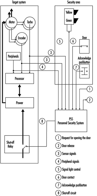
Requirements and Safety Measures in Normal Operation
The use of robot technology places maximum demands on hazard analysis, risk assessment and safety concepts. For this reason, the following examples and suggestions can serve only as guidelines:
1. Given the safety goal that manual or physical access to hazardous areas involving automatic movements must be prevented, suggested solutions include the following:
- Prevent manual or physical access into danger zones by means of mechanical barriers.
- Use safety devices of the sort which respond when approached (light barriers, safety mats), and take care to switch off machinery safely when accessed or entered.
- Permit manual or physical access only when the entire system is in a safe state. For example, this can be achieved by the use of interlocking devices with closure mechanisms on the access doors.
2. Given the safety goal that no person may be injured as a result of the release of energy (flying parts or beams of energy), suggested solutions include:
- Design should prevent any release of energy (e.g., correspondingly dimensioned connections, passive gripper interlocking devices for gripper change mechanisms, etc.).
- Prevent the release of energy from the danger zone, for example, by a correspondingly dimensioned safety hood.
3. The interfaces between normal operation and special operation (e.g., door interlocking devices, light barriers, safety mats) are necessary to enable the safety control system to automatically recognize the presence of personnel.
Demands and Safety Measures in Special Operation Modes
Certain special operation modes (e.g., setting up, programming) on an industrial robot require movements which must be assessed directly at the site of operation. The relevant safety goal is that no movements may endanger the persons involved. The movements should be
- only of the scheduled style and speed
- prolonged only as long as instructed
- those which may be performed only if it can be guaranteed that no parts of the human body are in the danger zone.
A suggested solution to this goal could involve the use of special operating control systems which permit only controllable and manageable movements using acknowledgeable controls. The speed of movements is thus safely reduced (energy reduction by the connection of an isolation transformer or the use of fail-safe state monitoring equipment) and the safe condition is acknowledged before the control is allowed to activate (see figure 3).
Figure 3. Six-axis industrial robot in a safety cage with material gates
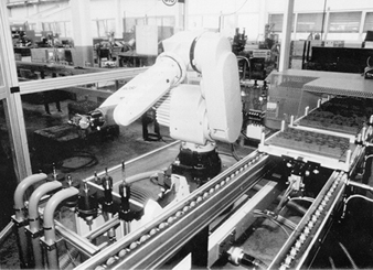
Demands on Safety Control Systems
One of the features of a safety control system must be that the required safety function is guaranteed to work whenever any faults arise. Industrial robot machines should be almost instantaneously directed from a hazardous state to a safe state. Safety control measures needed to achieve this include the following safety goals:
- A fault in the safety control system may not trigger off a hazardous state.
- A fault in the safety control system must be identified (immediately or at intervals).
Suggested solutions to providing reliable safety control systems would be:
- redundant and diverse layout of electro-mechanical control systems including test circuits
- redundant and diverse set-up of microprocessor control systems developed by different teams. This modern approach is considered to be state-of-the-art; for example, those complete with safety light barriers.
Safety Goals for the Construction and Use of Industrial Robots.
When industrial robots are built and used, both manufacturers as well as users are required to install state-of-the-art safety controls. Apart from the aspect of legal responsibility, there may also be a moral obligation to ensure that robot technology is also a safe technology.
Normal operation mode
The following safety conditions should be provided when robot machines are operating in the normal mode:
- The field of movement of the robot and the processing areas used by peripheral equipment must be secured in such a way as to prevent manual or physical access by persons to areas which are hazardous as a result of automatic movements.
- Protection should be provided so that flying workpieces or tools are not allowed to cause damage.
- No persons must be injured by parts, tools or workpieces ejected by the robot or by the release of energy, due to faulty gripper(s), gripper power failure, inadmissible speed, collision(s) or faulty workpiece(s).
- No persons may be injured by the release of energy or by parts ejected by peripheral equipment.
- Feed and removal apertures must be designed to prevent manual or physical access to areas which are hazardous as a result of automatic movements. This condition must also be fulfilled when production material is removed. If production material is fed to the robot automatically, no hazardous areas may be created by feed and removal apertures and the moving production material.
Special operation modes
The following safety conditions should be provided when robot machines are operating in special modes:
The following must be prevented during rectification of a breakdown in the production process:
- manual or physical access to areas which are hazardous due to automatic movements by the robot or by peripheral equipment
- hazards which arise from faulty behaviour on the part of the system or from inadmissible command input if persons or parts of the body are in the area exposed to hazardous movements
- hazardous movements or conditions initiated by the movement or removal of production material or waste products
- injuries caused by peripheral equipment
- movements that have to be carried out with the safety guard(s) for normal operation removed, to be carried out only within the operational scope and speed, and only as long as instructed. Additionally, no person(s) or parts of the body may be present in the area at risk.
The following safe conditions should be assured during set up:
No hazardous movements may be initiated as a result of a faulty command or incorrect command input.
- The replacement of robot machine or peripheral parts must not initiate any hazardous movements or conditions.
- If movements have to be carried out with the safety guard(s) for normal operation removed when conducting setting-up operations, such movements may be carried out only within the directed scope and speed and only as long as instructed. Additionally, no person(s) or parts of the body may be present in the area at risk.
- During setting-up operations, the peripheral equipment must not make any hazardous movements or initiate any hazardous conditions.
During programming, the following safety conditions are applicable:
- Manual or physical access to areas which are hazardous due to automatic movements must be prevented.
- If movements are carried out with the safety guard(s) for normal operation removed, the following conditions must be fulfilled:
- (a)Only the command to move may be carried out, and only for as long as it is issued.
- (b)Only controllable movements may be carried out (i.e., they must be clearly visible, low-speed movements).
- (c)Movements may be initiated only if they do not constitute a hazard to the programmer or other persons.
- Peripheral equipment must not represent a hazard to the programmer or other persons.
Safe test operations require the following precautions:
Prevent manual or physical access to areas which are hazardous due to automatic movements.
- Peripheral equipment must not be a source of danger.
When inspecting robot machines, safe procedures include the following:
- If it is necessary to enter the robot’s field of movement for inspection purposes, this is permissible only if the system is in a safe state.
- Hazards caused by faulty behaviour on the part of the system or by inadmissible command input must be prevented.
- Peripheral equipment must not be a source of danger to inspection personnel.
Troubleshooting often requires starting the robot machine while it is in a potentially hazardous condition, and special safe work procedures such as the following should be implemented:
- Access to areas which are hazardous as a result of automatic movements must be prevented.
- The starting up of a drive unit as a result of a faulty command or false command input must be prevented.
- In handling a defective part, all movements on the part of the robot must be prevented.
- Injuries caused by machine parts which are ejected or fall off must be prevented.
- If, during troubleshooting, movements have to be carried out with the safety guard(s) for normal operation removed, such movements may be carried out only within the scope and speed laid down and only as long as instructed. Additionally, no person(s) or parts of the body may be present in the area at risk.
- Injuries caused by peripheral equipment must be prevented.
Remedying a fault and maintenance work also may require start-up while the machine is in an unsafe condition, and therefore require the following precautions:
- The robot must not be able to start up.
- The handling of various machine parts, either manually or with ancillary equipment, must be possible without risk of exposure to hazards.
- It must not be possible to touch parts that are “live”.
- Injuries caused by the escape of liquid or gaseous media must be prevented.
- Injuries caused by peripheral equipment must be prevented.
Electrical, Electronic and Programmable Electronic Safety-Related Control Systems
This article discusses the design and implementation of safety- related control systems which deal with all types of electrical, electronic and programmable-electronic systems (including computer-based systems). The overall approach is in accordance with proposed International Electrotechnical Commission (IEC) Standard 1508 (Functional Safety: Safety-Related
Systems) (IEC 1993).
Background
During the 1980s, computer-based systems—generically referred to as programmable electronic systems (PESs)—were increasingly being used to carry out safety functions. The primary driving forces behind this trend were (1) improved functionality and economic benefits (particularly considering the total life cycle of the device or system) and (2) the particular benefit of certain designs, which could be realized only when computer technology was used. During the early introduction of computer-based systems a number of findings were made:
- The introduction of computer control was poorly thought out and planned.
- Inadequate safety requirements were specified.
- Inadequate procedures were developed with respect to the validation of software.
- Evidence of poor workmanship was disclosed with respect to the standard of plant installation.
- Inadequate documentation was generated and not adequately validated with respect to what was actually in the plant (as distinct from what was thought to be in the plant).
- Less than fully effective operation and maintenance procedures had been established.
- There was evidently justified concern about the competence of persons to perform the duties required of them.
In order to solve these problems, several bodies published or began developing guidelines to enable the safe exploitation of PES technology. In the United Kingdom, the Health and Safety Executive (HSE) developed guidelines for programmable electronic systems used for safety-related applications, and in Germany, a draft standard (DIN 1990) was published. Within the European Community, an important element in the work on harmonized European Standards concerned with safety-related control systems (including those employing PESs) was started in connection with the requirements of the Machinery Directive. In the United States, the Instrument Society of America (ISA) has produced a standard on PESs for use in the process industries, and the Center for Chemical Process Safety (CCPS), a directorate of the American Institute of Chemical Engineers, has produced guidelines for the chemical process sector.
A major standards initiative is currently taking place within the IEC to develop a generically based international standard for electrical, electronic and programmable electronic (E/E/PES) safety-related systems that could be used by the many applications sectors, including the process, medical, transport and machinery sectors. The proposed IEC international standard comprises seven Parts under the general title IEC 1508. Functional safety of electrical/electronic/programmable electronic safety-related systems. The various Parts are as follows:
- Part 1.General requirements
- Part 2.Requirements for electrical, electronic and programmable electronic systems
- Part 3.Software requirements
- Part 4.Definitions
- Part 5.Examples of methods for the determination of safety integrity levels
- Part 6.Guidelines on the application of Parts 2 and 3
- Part 7.Overview of techniques and measures.
When finalized, this generically based International Standard will constitute an IEC basic safety publication covering functional safety for electrical, electronic and programmable electronic safety-related systems and will have implications for all IEC standards, covering all application sectors as regards the future design and use of electrical/electronic/programmable electronic safety-related systems. A major objective of the proposed standard is to facilitate the development of standards for the various sectors (see figure 1).
Figure 1. Generic and application sector standards
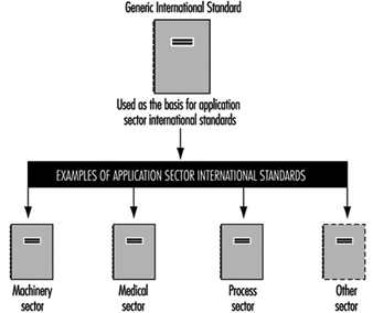
PES Benefits and Problems
The adoption of PESs for safety purposes had many potential advantages, but it was recognized that these would be achieved only if appropriate design and assessment methodologies were used, because: (1) many of the features of PESs do not enable the safety integrity (that is, the safety performance of the systems carrying out the required safety functions) to be predicted with the same degree of confidence that has traditionally been available for less complex hardware-based (“hardwired”) systems; (2) it was recognized that while testing was necessary for complex systems, it was not sufficient on its own. This meant that even if the PES was implementing relatively simple safety functions, the level of complexity of the programmable electronics was significantly greater than that of the hardwired systems they were replacing; and (3) this rise in complexity meant that the design and assessment methodologies had to be given much more consideration than previously, and that the level of personal competence required to achieve adequate levels of performance of the safety-related systems was subsequently greater.
The benefits of computer-based PESs include the following:
- the ability to perform on-line diagnostic proof checks on critical components at a frequency significantly higher than would otherwise be the case
- the potential to provide sophisticated safety interlocks
- the ability to provide diagnostic functions and condition monitoring which can be used to analyse and report on the performance of plant and machinery in real time
- the capability of comparing actual conditions of the plant with “ideal” model conditions
- the potential to provide better information to operators and hence to improve decision-making affecting safety
- the use of advanced control strategies to enable human operators to be located remotely from hazardous or hostile environments
- the ability to diagnose the control system from a remote location.
The use of computer-based systems in safety-related applications creates a number of problems which need to be adequately addressed, such as the following:
- The failure modes are complex and not always predictable.
- Testing the computer is necessary but is not sufficient in itself to establish that the safety functions will be performed with the degree of certainty required for the application.
- Microprocessors may have subtle variations between different batches, and therefore different batches may display different behaviour.
- Unprotected computer-based systems are particularly susceptible to electrical interference (radiated interference; electrical “spikes” in the mains supplies, electrostatic discharges, etc.).
- It is difficult and often impossible to quantify the probability of failure of complex safety-related systems incorporating software. Because no method of quantification has been widely accepted, software assurance has been based on procedures and standards which describe the methods to be used in the design, implementation and maintenance of the software.
Safety Systems under Consideration
The types of safety-related systems under consideration are electrical, electronic and programmable electronic systems (E/E/PESs). The system includes all elements, particularly signals extending from sensors or from other input devices on the equipment under control, and transmitted via data highways or other communication paths to the actuators or other output devices (see figure 2).
Figure 2. Electrical, electronic and programmable electronic system (E/E/PES)
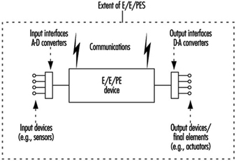
The term electrical, electronic and programmable electronic device has been used to encompass a wide variety of devices and covers the following three chief classes:
- electrical devices such as electro-mechanical relays
- electronic devices such as solid state electronic instruments and logic systems
- programmable electronic devices, which includes a wide variety of computer-based systems such as the following:
- microprocessors
- micro-controllers
- programmable controllers (PCs)
- application-specific integrated circuits (ASICs)
- programmable logic controllers (PLCs)
- other computer-based devices (e.g., “smart” sensors, transmitters and actuators).
By definition, a safety-related system serves two purposes:
- It implements the required safety functions necessary to achieve a safe state for the equipment under control or maintains a safe state for the equipment under control. The safety-related system must perform those safety functions that are specified in the safety functions requirements specification for the system. For example, the safety functions requirements specification may state that when the temperature reaches a certain value x, valve y shall open to allow water to enter the vessel.
- It achieves, on its own or with other safety-related systems, the necessary level of safety integrity for the implementation of the required safety functions. The safety functions must be performed by the safety-related systems with the degree of confidence appropriate to the application in order to achieve the required level of safety for the equipment under control.
This concept is illustrated in figure 3.
Figure 3. Key features of safety-related systems
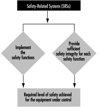
System Failures
In order to ensure safe operation of E/E/PES safety-related systems, it is necessary to recognize the various possible causes of safety-related system failure and to ensure that adequate precautions are taken against each. Failures are classified into two categories, as illustrated in figure 4.
Figure 4. Failure categories
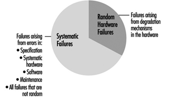
- Random hardware failures are those failures which result from a variety of normal degradation mechanisms in the hardware. There are many such mechanisms occurring at different rates in different components, and since manufacturing tolerances cause components to fail on account of these mechanisms after different times in operation, failures of a total item of equipment comprising many components occur at unpredictable (random) times. Measures of system reliability, such as the mean time between failures (MTBF), are valuable but are usually concerned only with random hardware failures and do not include systematic failures.
- Systematic failures arise from errors in the design, construction or use of a system which cause it to fail under some particular combination of inputs or under some particular environmental condition. If a system failure occurs when a particular set of circumstances arises, then whenever those circumstances arise in the future there will always be a system failure. Any failure of a safety-related system which does not arise from a random hardware failure is, by definition, a systematic failure. Systematic failures, in the context of E/E/PES safety-related systems, include:
- systematic failures due to errors or omissions in the safety functions requirements specification
- systematic failures due to errors in the design, manufacture, installation or operation of the hardware. These would include failures arising from environmental causes and human (e.g., operator) error
- systematic failures due to faults in the software
- systematic failures due to maintenance and modification errors.
Protection of Safety-Related Systems
The terms that are used to indicate the precautionary measures required by a safety-related system to protect against random hardware failures and systematic failures are hardware safety integrity measures and systematic safety integrity measures respectively. Precautionary measures that a safety-related system can bring to bear against both random hardware failures and systematic failures are termed safety integrity. These concepts are illustrated in figure 5.
Figure 5. Safety performance terms
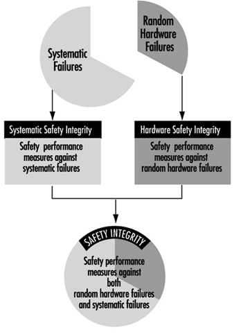
Within the proposed international standard IEC 1508 there are four levels of safety integrity, denoted Safety Integrity Levels 1, 2, 3 and 4. Safety Integrity Level 1 is the lowest safety integrity level and Safety Integrity Level 4 is the highest. The Safety Integrity Level (whether 1, 2, 3 or 4) for the safety-related system will depend upon the importance of the role the safety-related system is playing in achieving the required level of safety for the equipment under control. Several safety-related systems may be necessary—some of which may be based on pneumatic or hydraulic technology.
Design of Safety-Related Systems
A recent analysis of 34 incidents involving control systems (HSE) found that 60% of all cases of failure had been “built in” before the safety-related control system had been put into use (figure 7). Consideration of all the safety life cycle phases is necessary if adequate safety-related systems are to be produced.
Figure 7. Primary cause (by phase) of control system failure
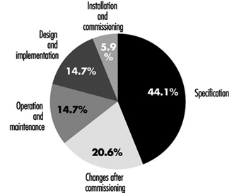
Functional safety of safety-related systems depends not only on ensuring that the technical requirements are properly specified but also in ensuring that the technical requirements are effectively implemented and that the initial design integrity is maintained throughout the life of the equipment. This can be realized only if an effective safety management system is in place and the people involved in any activity are competent with respect to the duties they have to perform. Particularly when complex safety-related systems are involved, it is essential that an adequate safety management system is in place. This leads to a strategy that ensures the following:
- An effective safety management system is in place.
- The technical requirements that are specified for the E/E/PES safety-related systems are sufficient to deal with both random hardware and systematic failure causes.
- The competence of the people involved is adequate for the duties they have to perform.
In order to address all the relevant technical requirements of functional safety in a systematic manner, the concept of the Safety Lifecycle has been developed. A simplified version of the Safety Lifecycle in the emerging international standard IEC 1508 is shown in figure 8. The key phases of the Safety Lifecycle are:
Figure 8. Role of the Safety Lifecycle in achieving functional safety
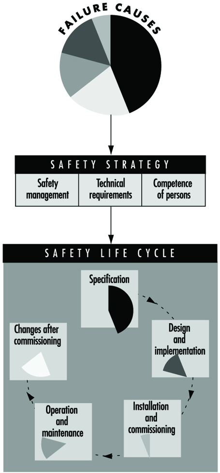
- specification
- design and implementation
- installation and commissioning
- operation and maintenance
- changes after commissioning.
Level of Safety
The design strategy for the achievement of adequate levels of safety integrity for the safety-related systems is illustrated in figure 9 and figure 10. A safety integrity level is based on the role the safety-related system is playing in the achievement of the overall level of safety for the equipment under control. The safety integrity level specifies the precautions that need to be taken into account in the design against both random hardware and systematic failures.
Figure 9. Role of safety integrity levels in the design process
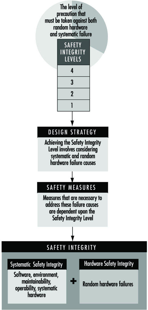
Figure 10. Role of the Safety Lifecycle in the specification and design process
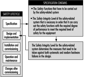
The concept of safety and level of safety applies to the equipment under control. The concept of functional safety applies to the safety-related systems. Functional safety for the safety-related systems has to be achieved if an adequate level of safety is to be achieved for the equipment that is giving rise to the hazard. The specified level of safety for a specific situation is a key factor in the safety integrity requirements specification for the safety-related systems.
The required level of safety will depend upon many factors—for example, the severity of injury, the number of people exposed to danger, the frequency with which people are exposed to danger and the duration of the exposure. Important factors will be the perception and views of those exposed to the hazardous event. In arriving at what constitutes an appropriate level of safety for a specific application, a number of inputs are considered, which include the following:
- legal requirements relevant to the specific application
- guidelines from the appropriate safety regulatory authority
- discussions and agreements with the different parties involved in the application
- industry standards
- national and international standards
- the best independent industrial, expert and scientific advice.
Summary
When designing and using safety-related systems, it must be remembered that it is the equipment under control that creates the potential hazard. The safety-related systems are designed to reduce the frequency (or probability) of the hazardous event and/or the consequences of the hazardous event. Once the level of safety has been set for the equipment, the safety integrity level for the safety-related system can be determined, and it is the safety integrity level that allows the designer to specify the precautions that need to be built into the design to be deployed against both random hardware and systematic failures.
Technical Requirements for Safety-Related Systems Based on Electrical, Electronic and Programmable Electronic Devices
Machinery, process plants and other equipment can, if they malfunction, present risks from hazardous events such as fires, explosions, radiation overdoses and moving parts. One of the ways such plants, equipment and machinery can malfunction is from failures of electro-mechanical, electronic and programmable electronic (E/E/PE) devices used in the design of their control or safety systems. These failures can arise either from physical faults in the device (e.g., from wear and tear occurring randomly in time (random hardware failures)); or from systematic faults (e.g., errors made in the specification and design of a system that cause it to fail due to (1) some particular combination of inputs, (2) some environmental condition (3) incorrect or incomplete inputs from sensors, (4) incomplete or erroneous data entry by operators, and (5) potential systematic faults due to poor interface design).
Safety-Related Systems Failures
This article covers the functional safety of safety-related control systems, and considers the hardware and software technical requirements necessary to achieve the required safety integrity. The overall approach is in accordance with the proposed International Electrotechnical Commission Standard IEC 1508, Parts 2 and 3 (IEC 1993). The overall goal of draft international standard IEC 1508, Functional Safety: Safety-Related Systems, is to ensure that plant and equipment can be safety automated. A key objective in the development of the proposed international standard is to prevent or minimize the frequency of:
- failures of control systems triggering other events which in turn could lead to danger (e.g., control system fails, control is lost, process goes out of control resulting in a fire, release of toxic materials, etc.)
- failures in alarm and monitoring systems so that operators are not given information in a form that can be quickly identified and understood in order to carry out the necessary emergency actions
- undetected failures in protection systems, making them unavailable when needed for a safety action (e.g., a failed input card in an emergency shut-down system).
The article “Electrical, electronic and programmable electronic safety-related systems” sets out the general safety management approach embodied within Part 1 of IEC 1508 for assuring the safety of control and protection systems that are important to safety. This article describes the overall conceptual engineering design that is needed to reduce the risk of an accident to an acceptable level, including the role of any control or protection systems based on E/E/PE technology.
In figure 1, the risk from the equipment, process plant or machine (generally referred to as equipment under control (EUC) without protective devices) is marked at one end of the EUC Risk Scale, and the target level of risk that is needed to meet the required level of safety is at the other end. In between is shown the combination of safety-related systems and external risk reduction facilities needed to make up the required risk reduction. These can be of various types—mechanical (e.g., pressure relief valves), hydraulic, pneumatic, physical, as well as E/E/PE systems. Figure 2 emphasizes the role of each safety layer in protecting the EUC as the accident progresses.
Figure 1. Risk reduction: General concepts
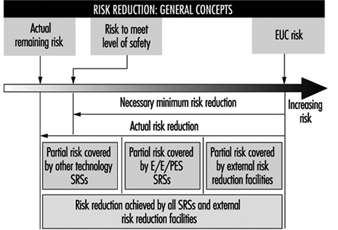
Figure 2. Overall model: Protection layers
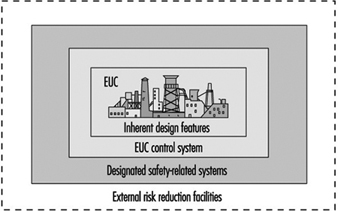
Provided that a hazard and risk analysis has been performed on the EUC as required in Part 1 of IEC 1508, the overall conceptual design for safety has been established and therefore the required functions and Safety Integrity Level (SIL) target for any E/E/PE control or protection system have been defined. The Safety Integrity Level target is defined with respect to a Target Failure Measure (see table 1).
Table 1. Safety Integrity Levels for protection systems: Target failure measures
Safety integrity Level Demand mode of operation (Probability of failure to perform its design function on demand)
4 10-5 ≤ × 10-4
3 10-4 ≤ × 10-3
2 10-3 ≤ × 10-2
1 10-2 ≤ × 10-1
Protection Systems
This paper outlines the technical requirements that the designer of an E/E/PE safety-related system should consider to satisfy the required Safety Integrity Level target. The focus is on a typical protection system utilizing programmable electronics in order to allow for a more in-depth discussion of the key issues with little loss in generality. A typical protection system is shown in figure 3, which depicts a single channel safety system with a secondary switch-off activated via a diagnostic device. In normal operation the unsafe condition of the EUC (e.g., overspeed in a machine, high temperature in a chemical plant) will be detected by the sensor and transmitted to the programmable electronics, which will command the actuators (via the output relays) to put the system into a safe state (e.g., removing power to electric motor of the machine, opening a valve to relieve pressure).
Figure 3. Typical protection system
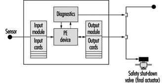
But what if there are failures in the protection system components? This is the function of the secondary switch-off, which is activated by the diagnostic (self-checking) feature of this design. However, the system is not completely fail-safe, as the design has only a certain probability of being available when being asked to carry out its safety function (it has a certain probability of failure on demand or a certain Safety Integrity Level). For example, the above design might be able to detect and tolerate certain types of output card failure, but it would not be able to withstand a failure of the input card. Therefore, its safety integrity will be much lower than that of a design with a higher-reliability input card, or improved diagnostics, or some combination of these.
There are other possible causes of card failures, including “traditional” physical faults in the hardware, systematic faults including errors in the requirements specification, implementation faults in the software and inadequate protection against environmental conditions (e.g., humidity). The diagnostics in this single-channel design may not cover all these types of faults, and therefore this will limit the Safety Integrity Level achieved in practice. (Coverage is a measure of the percentage of faults that a design can detect and handle safely.)
Technical Requirements
Parts 2 and 3 of draft IEC 1508 provide a framework for identifying the various potential causes of failure in hardware and software and for selecting design features that overcome those potential causes of failure appropriate to the required Safety Integrity Level of the safety-related system. For example, the overall technical approach for the protection system in figure 3 is shown in figure 4. The figure indicates the two basic strategies for overcoming faults and failures: (1) fault avoidance, where care is taken in to prevent faults being created; and (2) fault tolerance, where the design is created specifically to tolerate specified faults. The single-channel system mentioned above is an example of a (limited) fault tolerant design where diagnostics are used to detect certain faults and put the system into a safe state before a dangerous failure can occur.
Figure 4. Design specification: Design solution
Fault avoidance
Fault avoidance attempts to prevent faults being introduced into a system. The main approach is to use a systematic method of managing the project so that safety is treated as a definable and manageable quality of a system, during design and then subsequently during operation and maintenance. The approach, which is similar to quality assurance, is based on the concept of feedback and involves: (1) planning (defining safety objectives, identifying the ways and means to achieve the objectives); (2) measuring achievement against the plan during implementation and (3) applying feedback to correct for any deviations. Design reviews are a good example of a fault avoidance technique. In IEC 1508 this “quality” approach to fault avoidance is facilitated by the requirements to use a safety lifecycle and employ safety management procedures for both hardware and software. For the latter, these often manifest themselves as software quality assurance procedures such as those described in ISO 9000-3 (1990).
In addition, Parts 2 and 3 of IEC 1508 (concerning hardware and software, respectively) grade certain techniques or measures that are considered useful for fault avoidance during the various safety lifecycle phases. Table 2 gives an example from Part 3 for the design and development phase of software. The designer would use the table to assist in the selection of fault avoidance techniques, depending on the required Safety Integrity Level. With each technique or measure in the tables there is a recommendation for each Safety Integrity Level, 1 to 4. The range of recommendations covers Highly Recommended (HR), Recommended (R), Neutral—neither for or against (—) and Not Recommended (NR).
Table 2. Software design and development
|
Technique/measure |
SIL 1 |
SIL 2 |
SIL 3 |
SIL 4 |
|
1. Formal methods including, for example, CCS, CSP, HOL, LOTOS |
— |
R |
R |
HR |
|
2. Semi-formal methods |
HR |
HR |
HR |
HR |
|
3. Structured. Methodology including, for example, JSD, MASCOT, SADT, SSADM and YOURDON |
HR |
HR |
HR |
HR |
|
4. Modular approach |
HR |
HR |
HR |
HR |
|
5. Design and coding standards |
R |
HR |
HR |
HR |
HR = highly recommended; R = recommended; NR = not recommended;— = neutral: the technique/measure is neither for or against the SIL.
Note: a numbered technique/measure shall be selected according to the safety integrity level.
Fault tolerance
IEC 1508 requires increasing levels of fault tolerance as the safety integrity target increases. The standard recognizes, however, that fault tolerance is more important when systems (and the components that make up those systems) are complex (designated as Type B in IEC 1508). For less complex, “well proven” systems, the degree of fault tolerance can be relaxed.
Tolerance against random hardware faults
Table 3 shows the requirements for fault tolerance against random hardware failures in complex hardware components (e.g., microprocessors) when used in a protection system such as is shown in figure 3. The designer may need to consider an appropriate combination of diagnostics, fault tolerance and manual proof checks to overcome this class of fault, depending on the required Safety Integrity Level.
Table 3. Safety Integrity Level - Fault requirements for Type B components1
1 Safety-related undetected faults shall be detected by the proof check.
2 For components without on-line medium diagnostic coverage, the system shall be able to perform the safety function in the presence of a single fault. Safety-related undetected faults shall be detected by the proof check.
3 For components with on-line high diagnostic coverage, the system shall be able to perform the safety function in the presence of a single fault. For components without on-line high diagnostic coverage, the system shall be able to perform the safety function in the presence of two faults. Safety-related undetected faults shall be detected by the proof check.
4 The components shall be able to perform the safety function in the presence of two faults. Faults shall be detected with on-line high diagnostic coverage. Safety-related undetected faults shall be detected by the proof check. Quantitative hardware analysis shall be based on worst-case assumptions.
1Components whose failure modes are not well defined or testable, or for which there are poor failure data from field experience (e.g., programmable electronic components).
IEC 1508 aids the designer by providing design specification tables (see table 4) with design parameters indexed against the Safety Integrity Level for a number of commonly used protection system architectures.
Table 4. Requirements for Safety Integrity Level 2 - Programmable electronic system architectures for protection systems
|
PE system configuration |
Diagnostic coverage per channel |
Off-line proof test Interval (TI) |
Mean time to spurious trip |
|
Single PE, Single I/O, Ext. WD |
High |
6 months |
1.6 years |
|
Dual PE, Single I/O |
High |
6 months |
10 years |
|
Dual PE, Dual I/O, 2oo2 |
High |
3 months |
1,281 years |
|
Dual PE, Dual I/O, 1oo2 |
None |
2 months |
1.4 years |
|
Dual PE, Dual I/O, 1oo2 |
Low |
5 months |
1.0 years |
|
Dual PE, Dual I/O, 1oo2 |
Medium |
18 months |
0.8 years |
|
Dual PE, Dual I/O, 1oo2 |
High |
36 months |
0.8 years |
|
Dual PE, Dual I/O, 1oo2D |
None |
2 months |
1.9 years |
|
Dual PE, Dual I/O, 1oo2D |
Low |
4 months |
4.7 years |
|
Dual PE, Dual I/O, 1oo2D |
Medium |
18 months |
18 years |
|
Dual PE, Dual I/O, 1oo2D |
High |
48+ months |
168 years |
|
Triple PE, Triple I/O, IPC, 2oo3 |
None |
1 month |
20 years |
|
Triple PE, Triple I/O, IPC, 2oo3 |
Low |
3 months |
25 years |
|
Triple PE, Triple I/O, IPC, 2oo3 |
Medium |
12 months |
30 years |
|
Triple PE, Triple I/O, IPC, 2oo3 |
High |
48+ months |
168 years |
The first column of the table represents architectures with varying degrees of fault tolerance. In general, architectures placed near the bottom of the table have a higher degree of fault tolerance than those near the top. A 1oo2 (one out of two) system is able to withstand any one fault, as can 2oo3.
The second column describes the percentage coverage of any internal diagnostics. The higher the level of the diagnostics, the more faults will be trapped. In a protection system this is important because, provided the faulty component (e.g., an input card) is repaired within a reasonable time (often 8 hours), there is little loss in functional safety. (Note: this would not be the case for a continuous control system, because any fault is likely to cause an immediate unsafe condition and the potential for an incident.)
The third column shows the interval between proof tests. These are special tests that are required to be carried out to thoroughly exercise the protection system to ensure that there are no latent faults. Typically these are carried out by the equipment vendor during plant shutdown periods.
The fourth column shows the spurious trip rate. A spurious trip is one that causes the plant or equipment to shut down when there is no process deviation. The price for safety is often a higher spurious trip rate. A simple redundant protection system—1oo2—has, with all other design factors unchanged, a higher Safety Integrity Level but also a higher spurious trip rate than a single-channel (1oo1) system.
If one of the architectures in the table is not being used or if the designer wants to carry out a more fundamental analysis, then IEC 1508 allows this alternative. Reliability engineering techniques such as Markov modelling can then be used to calculate the hardware element of the Safety Integrity Level (Johnson 1989; Goble 1992).
Tolerance against systematic and common cause failures
This class of failure is very important in safety systems and is the limiting factor on the achievement of safety integrity. In a redundant system a component or subsystem, or even the whole system, is duplicated to achieve a high reliability from lower-reliability parts. Reliability improvement occurs because, statistically, the chance of two systems failing simultaneously by random faults will be the product of the reliabilities of the individual systems, and hence much lower. On the other hand, systematic and common cause faults cause redundant systems to fail coincidentally when, for example, a specification error in the software leads the duplicated parts to fail at the same time. Another example would be the failure of a common power supply to a redundant system.
IEC 1508 provides tables of engineering techniques ranked against the Safety Integrity Level considered effective in providing protection against systematic and common cause failures.
Examples of techniques providing defences against systematic failures are diversity and analytical redundancy. The basis of diversity is that if a designer implements a second channel in a redundant system using a different technology or software language, then faults in the redundant channels can be regarded as independent (i.e., a low probability of coincidental failure). However, particularly in the area of software-based systems, there is some suggestion that this technique may not be effective, as most mistakes are in the specification. Analytical redundancy attempts to exploit redundant information in the plant or machine to identify faults. For the other causes of systematic failure—for example, external stresses—the standard provides tables giving advice on good engineering practices (e.g., separation of signal and power cables) indexed against Safety Integrity Level.
Conclusions
Computer-based systems offer many advantages—not only economic, but also the potential for improving safety. However, the attention to detail required to realize this potential is significantly greater than is the case using conventional system components. This article has outlined the main technical requirements that a designer needs to take into account to successfully exploit this technology.
Rollover
Tractors and other mobile machinery in agricultural, forestry, construction and mining work, as well as materials handling, can give rise to serious hazards when the vehicles roll over sideways, tip over forwards or rear over backwards. The risks are heightened in the case of wheeled tractors with high centres of gravity. Other vehicles that present a hazard of rollover are crawler tractors, loaders, cranes, fruit-pickers, dozers, dumpers, scrapers and graders. These accidents usually happen too fast for drivers and passengers to get clear of the equipment, and they can become trapped under the vehicle. For example, tractors with high centres of gravity have considerable likelihood of rollover (and narrow tractors have even less stability than wide ones). A mercury engine cut-off switch to shut off power upon sensing lateral movement was introduced on tractors but was proven too slow to cope with the dynamic forces generated in the rollover movement (Springfeldt 1993). Therefore the safety device was abandoned.
The fact that such equipment often is used on sloping or uneven ground or on soft earth, and sometimes in close proximity to ditches, trenches or excavations, is an important contributing cause to rollover. If auxiliary equipment is attached high up on a tractor, the probability of rearing over backwards in climbing a slope (or tipping over forwards when descending) increases. Furthermore, a tractor can roll over because of the loss of control due to the pressure exerted by tractor-drawn equipment (e.g., when the carriage moves downwards on a slope and the attached equipment is not braked and over-runs the tractor). Special hazards arise when tractors are used as tow vehicles, particularly if the tow hook on the tractor is placed on a higher level than the wheel axle.
History
Notice of the rollover problem was taken on the national level in certain countries where many fatal rollovers occurred. In Sweden and New Zealand, development and testing of rollover protective structures (ROPS) on tractors (figure 1) already were in progress in the 1950s, but this work was followed up by regulations only on the part of the Swedish authorities; these regulations were effective from the year 1959 (Springfeldt 1993).
Figure 1. Usual types of ROPS on tractors
Proposed regulations prescribing ROPS for tractors were met by resistance in the agricultural sector in several countries. Strong opposition was mounted against plans requiring employers to install ROPS on existing tractors, and even against the proposal that only new tractors be equipped by the manufacturers with ROPS. Eventually many countries successfully mandated ROPS for new tractors, and later on some countries were able to require ROPS be retrofitted on old tractors as well. International standards concerning tractors and earth-moving machinery, including testing standards for ROPS, contributed to more reliable designs. Tractors were designed and manufactured with lower centres of gravity and lower-placed tow hooks. Four-wheel drive has reduced the risk of rollover. But the proportion of tractors with ROPS in countries with many old tractors and without mandates for retrofitting of ROPS is still rather low.
Investigations
Rollover accidents, particularly those involving tractors, have been studied by researchers in many countries. However, there are no centralized international statistics with respect to the number of accidents caused by the types of mobile machinery reviewed in this article. Available statistics at the national level nevertheless show that the number is high, especially in agriculture. According to a Scottish report of tractor rollover accidents in the period 1968–1976, 85% of the tractors involved had equipment attached at the time of the accident, and of these, half had trailed equipment and half had mounted equipment. Two-thirds of the tractor rollover accidents in the Scottish report occurred on slopes (Springfeldt 1993). It was later proved that the number of accidents would be reduced after the introduction of training for driving on slopes as well as the application of an instrument for measuring slope steepness combined with an indicator of safe slope limits.
In other investigations, New Zealand researchers observed that half of their fatal rollover accidents occurred on flat ground or on slight slopes, and only one-tenth occurred on steep slopes. On flat ground tractor drivers may be less attentive to rollover hazards, and they can misjudge the risk posed by ditches and uneven ground. Of the rollover fatalities in tractors in New Zealand in the period 1949–1980, 80% occurred in wheel tractors, and 20% with crawler tractors (Springfeldt 1993). Studies in Sweden and New Zealand showed that about 80% of the tractor rollover fatalities occurred when tractors rolled over sideways. Half of the tractors involved in the New Zealand fatalities had rolled 180°.
Studies of the correlation between rollover fatalities in West Germany and the model year of farm tractors (Springfeldt 1993) showed that 1 of 10,000 old, unprotected tractors manufactured before 1957 was involved in a rollover fatality. Of tractors with prescribed ROPS, manufactured in 1970 and later, 1 of 25,000 tractors was involved in a rollover fatality. Of fatal tractor rollovers in West Germany in the period 1980–1985, two-thirds of the victims were thrown from their protected area and then run over or hit by the tractor (Springfeldt 1993). Of nonfatal rollovers, one-quarter of the drivers were thrown from the driver’s seat but not run over. It is evident that the fatality risk increases if the driver is thrown out of the protected area (similar to automobile accidents). Most of the tractors involved had a two-pillar bow (figure 1 C) that does not prevent the driver from being thrown out. In a few cases the ROPS had been subject to breakage or strong deformation.
The relative frequencies of injuries per 100,000 tractors in different periods in some countries and the reduction of the fatality rate was calculated by Springfeldt (1993). The effectiveness of ROPS in diminishing injury in tractor rollover accidents has been proven in Sweden, where the number of fatalities per 100,000 tractors was reduced from approximately 17 to 0.3 over the period of three decades (1960–1990) (figure 2). At the end of the period it was estimated that about 98% of the tractors were fitted with ROPS, mainly in the form of a crushproof cab (figure 1 A). In Norway, fatalities were reduced from about 24 to 4 per 100,000 tractors during a similar period. However, worse results were achieved in Finland and New Zealand.
Figure 2. Injuries by rollovers per 100,000 tractors in Sweden between 1957 and 1990
Prevention of Injuries by Rollovers
The risk of rollover is greatest in the case of tractors; however, in agricultural and forest work there is little that can be done to prevent tractors from rolling over. By mounting ROPS on tractors and those types of earth-moving machinery with potential rollover hazards, the risk of personal injuries can be reduced, provided that the drivers remain on their seats during rollover events (Springfeldt 1993). The frequency of rollover fatalities depends largely on the proportion of protected machines in use and the types of ROPS used. A bow (figure 1 C) gives much less protection than a cab or a frame (Springfeldt 1993). The most effective structure is a crushproof cab, which allows the driver to stay inside, protected, during a rollover. (Another reason for choosing a cab is that it affords weather protection.) The most effective means of keeping the driver within the protection of the ROPS during a rollover is a seat-belt, provided that the driver uses the belt while operating the equipment. In some countries, there are information plates at the driver’s seat advising that the steering wheel be gripped in a rollover event. An additional safety measure is to design the driver’s cab or interior environment and the ROPS so as to prevent exposure to hazards such as sharp edges or protuberances.
In all countries, rollovers of mobile machinery, mainly tractors, are causing serious injures. There are, however, considerable differences among countries concerning technical specifications relating to machinery design, as well as administrative procedures for examinations, testing, inspections and marketing. The international diversity that characterizes safety efforts in this connection may be explained by considerations such as the following:
- whether there exist mandatory requirements for ROPS (in the form of regulations or legislation), or recommendations only, or no rules at all
- the need for rules for new machinery and rules applicable to older equipment
- the availability of inspection carried out by authorities and the existence of social pressure and cultural climate favourable to observance of safety rules; in many countries, the obedience to safety guidelines is not checked by inspection in agricultural work
- pressure from trade unions; however, it should be borne in mind that workers’ organizations have less influence on working conditions in agriculture than in other sectors, because there are many family farms in agriculture
- the type of ROPS used in the country
- information and understanding of the risks to which tractor drivers are exposed; practical problems often stand in the way of reaching farmers and forest workers for the purposes of information and education
- the geography of the country, especially where agricultural, forestry and road work is carried out.
Safety Regulations
The nature of rules governing requirements for ROPS and the degree of implementation of the rules in a country, has a strong influence on rollover accidents, especially fatal ones. With this in mind, the development of safer machinery has been abetted by directives, codes and standards issued by international and national organizations. Additionally, many countries have adopted rigorous prescriptions for ROPS which have resulted in a great reduction of rollover injuries.
European Economic Community
Beginning in 1974 the European Economic Community (EEC) issued directives concerning type-approval of wheeled agricultural and forestry tractors, and in 1977 issued further, special directives concerning ROPS, including their attachment to tractors (Springfeldt 1993; EEC 1974, 1977, 1979, 1982, 1987). The directives prescribe a procedure for type-approval and certification by manufacture of tractors, and ROPS must be reviewed by an EEC Type Approval Examination. The directives have won acceptance by all the member countries.
Some EEC directives concerning ROPS on tractors were repealed as of 31 December 1995 and replaced by the general machinery directive which applies to those sorts of machinery presenting hazards due to their mobility (EEC 1991). Wheeled tractors, as well as some earth-moving machinery with a capacity exceeding 15 kW (namely crawlers and wheel loaders, backhoe loaders, crawler tractors, scrapers, graders and articulated dumpers) must be fitted with a ROPS. In case of a rollover, the ROPS must offer the driver and operators an adequate deflection-limiting volume (i.e., space allowing movement of occupants’ bodies before contacting interior elements during an accident). It is the responsibility of the manufacturers or their authorized representatives to perform appropriate tests.
Organization for Economic Cooperation and Development
In 1973 and 1987 the Organization for Economic Cooperation and Development (OECD) approved standard codes for testing of tractors (Springfeldt 1993; OECD 1987). They give results of tests of tractors and describe the testing equipment and test conditions. The codes require testing of many machinery parts and functions, for instance the strength of ROPS. The OECD Tractor Codes describe a static and a dynamic method of testing ROPS on certain types of tractors. A ROPS may be designed solely to protect the driver in the event of tractor rollover. It must be retested for each model of tractor to which the ROPS is to be fitted. The Codes also require that it be possible to mount a weather protection for the driver onto the structure, of a more or less temporary nature. The Tractor Codes have been accepted by all OECD member bodies from 1988, but in practice the United States and Japan also accept ROPS that do not comply with the code requirements if safety belts are provided (Springfeldt 1993).
International Labour Organization
In 1965, the International Labour Organization (ILO) in its manual, Safety and Health in Agricultural Work, required that a cab or a frame of sufficient strength be adequately fixed to tractors in order to provide satisfactory protection for the driver and passengers inside the cab in case of tractor rollover (Springfeldt 1993; ILO 1965). According to ILO Codes of Practice, agricultural and forestry tractors should be provided with ROPS to protect the operator and any passenger in case of rollover, falling objects or displaced loads (ILO 1976).
The fitting of ROPS should not adversely affect
- access between the ground and driver’s position
- access to the tractor’s main controls
- the manoeuvrability of the tractor in cramped surroundings
- the attachment or use of any equipment that may be connected to the tractor
- the control and adjustment of associated equipment.
International and national standards
In 1981 the International Organization for Standardization (ISO) issued a standard for tractors and machinery for agriculture and forestry (ISO 1981). The standard describes a static test method for ROPS and sets forth acceptance conditions. The standard has been approved by the member bodies in 22 countries; however, Canada and the United States have expressed disapproval of the document on technical grounds. A Standard and Recommended Practice issued in 1974 by the Society of Automotive Engineers (SAE) in North America contains performance requirements for ROPS on wheeled agricultural tractors and industrial tractors used in construction, rubber-tired scrapers, front-end loaders, dozers, crawler loaders, and motor graders (SAE 1974 and 1975). The contents of the standard have been adopted as regulations in the United States and in the Canadian provinces of Alberta and British Columbia.
Rules and Compliance
OECD Codes and International Standards concern the design and construction of ROPS as well as the control of their strength, but lack the authority to require that this sort of protection be put into practice (OECD 1987; ISO 1981). The European Economic Community also proposed that tractors and earth-moving machinery be equipped with protection (EEC 1974-1987). The aim of the EEC directives is to achieve uniformity among national entities concerning the safety of new machinery at the manufacturing stage. The member countries are obliged to follow the directives and issue corresponding prescriptions. Starting in 1996, the member countries of the EEC intend to issue regulations requiring that new tractors and earth-moving machinery be fitted with ROPS.
In 1959, Sweden became the first country to require ROPS for new tractors (Springfeldt 1993). Corresponding requirements came into effect in Denmark and Finland ten years later. Later on, in the 1970s and 1980s, mandatory requirements for ROPS on new tractors became effective in Great Britain, West Germany, New Zealand, the United States, Spain, Norway, Switzerland and other countries. In all these countries except the United States, the rules were extended to old tractors some years later, but these rules were not always mandatory. In Sweden, all tractors must be equipped with a protective cab, a rule that in Great Britain applies only to all tractors used by agricultural workers (Springfeldt 1993). In Denmark, Norway and Finland, all tractors must be provided with at least a frame, while in the United States and the Australian states, bows are accepted. In the United States tractors must have seat-belts.
In the United States, materials-handling machinery that was manufactured before 1972 and is used in construction work must be equipped with ROPS which meet minimum performance standards (US Bureau of National Affairs 1975). The machines covered by the requirement include some scrapers, front-end loaders, dozers, crawler tractors, loaders, and motor graders. Retrofitting was carried out of ROPS on machines manufactured about three years earlier.
Summary
In countries with mandatory requirements for ROPS for new tractors and retrofitting of ROPS on old tractors, there has been a decrease of rollover injuries, especially fatal ones. It is evident that a crushproof cab is the most effective type of ROPS. A bow gives poor protection in case of rollover. Many countries have prescribed effective ROPS at least on new tractors and as of 1996 on earth-moving machines. In spite of this fact some authorities seem to accept types of ROPS that do not comply with such requirements as have been promulgated by the OECD and the ISO. It is expected that a more general harmonization of the rules governing ROPS will be accomplished gradually all over the world, including the developing countries.
" DISCLAIMER: The ILO does not take responsibility for content presented on this web portal that is presented in any language other than English, which is the language used for the initial production and peer-review of original content. Certain statistics have not been updated since the production of the 4th edition of the Encyclopaedia (1998)."