- You are here:
-
Home

-
Contents
-
Part XV. Transport Industries
- Aerospace Manufacture and Maintenance

90. Aerospace Manufacture and Maintenance
Chapter Editor: Buck Cameron
Table of Contents
Tables and Figures
The Aerospace Industry
Buck Cameron
Safety and Ergonomics in Airframe Manufacturing
Douglas F. Briggs
Fall Protection for Transport Category Aircraft Manufacture and Maintenance
Robert W. Hites
Aircraft Engine Manufacturing
John B. Feldman
Controls and Health Effects
Denis Bourcier
Environmental and Public Health Issues
Steve Mason
Tables
Click a link below to view table in article context.
1. Aircraft & aerospace industry hazards
2. Technological development requirements
3. Toxicological considerations
4. Hazards of chemicals in aerospace
5. Summary of the United States NESHAP
6. Typical chemical hazards
7. Typical emission-control practices
Figures
Point to a thumbnail to see figure caption, click to see figure in article context.


The Aerospace Industry
General Profile
History and future trends
When Wilbur and Orville Wright made their first successful flight in 1903, aircraft manufacturing was a craft practised in the small shops of experimenters and adventurers. The small but dramatic contributions made by military aircraft during the First World War helped to take manufacturing out of the workshop and into mass production. Second-generation aircraft helped post-war operators to make inroads into the commercial sphere, particularly as carriers of mail and express cargo. Airliners, however, remained unpressurized, poorly heated and unable to fly above the weather. Despite these drawbacks, passenger travel increased by 600% from 1936 to 1941, but was still a luxury that relatively few experienced. The dramatic advances in aeronautical technology and the concomitant use of air power during the Second World War fostered the explosive growth of aircraft manufacturing capacity that survived the war in the United States, the United Kingdom and the Soviet Union. Since the Second World War, tactical and strategic missiles, reconnaissance and navigational satellites and piloted aircraft have taken on ever greater military significance. Satellite communication, geo-monitoring and weather-tracking technology have become of increasing commercial importance. The introduction of turbojet-powered civilian aircraft in the late 1950s made air travel faster and more comfortable and began a dramatic growth in commercial air travel. By 1993 over 1.25 trillion passenger miles were flown worldwide annually. This figure is projected to nearly triple by 2013.
Employment patterns
Employment in aerospace industries is highly cyclical. Direct aerospace employment in the European Union, North America and Japan peaked at 1,770,000 in 1989 before decreasing to 1,300,000 in 1995, with much of the employment loss occurring in the United States and the United Kingdom. The large aerospace industry in the Confederation of Independent States has been significantly disrupted subsequent to the break-up of the Soviet Union. Small but rapidly growing manufacturing capability exists in India and China. Manufacture of intercontinental and space missiles and long-range bombers has been largely restricted to the United States and the former Soviet Union, with France having developed commercial space launch capabilities. Shorter-range strategic missiles, tactical missiles and bombers, commercial rockets and fighter aircraft are more widely manufactured. Large commercial aircraft (those with 100 or greater seat capacity) are built by, or in cooperation with, manufacturers based in the United States and Europe. The manufacture of regional aircraft (less than 100 seat capacity) and business jets is more dispersed. The manufacture of aircraft for private pilots, based primarily in the United States, decreased from nearly 18,000 aircraft in 1978 to fewer than 1,000 in 1992 before rebounding.
Employment is divided in roughly equal measures among the manufacture of military aircraft, commercial aircraft, missiles and space vehicles and related equipment. Within individual enterprises, engineering, manufacturing and administrative positions each account for approximately one-third of the employed population. Males account for about 80% of the aerospace engineering and production workforce, with the overwhelming majority of highly skilled craftspeople, engineers and production managers being male.
Industry divisions
The markedly different needs and practices of governmental and civilian customers typically result in the segmentation of aerospace manufacturers into defense and commercial companies, or divisions of larger corporations. Airframes, engines (also called powerplants) and avionics (electronic navigational, communication and flight control equipment) are generally supplied by separate manufacturers. Engines and avionics each may account for one-quarter of the final cost of an airliner. Aerospace manufacturing requires the design, fabrication and assembly, inspection and testing of a vast array of components. Manufacturers have formed interconnected arrays of subcontractors and external and internal suppliers of components to meet their needs. Economic, technological, marketing and political demands have led to an increasing globalization of the manufacture of aircraft components and sub-assemblies.
Manufacturing Materials, Facilities and Processes
Materials
Airframes were originally made from wood and fabric, and then evolved to metal structural components. Aluminium alloys have been widely used due to their strength and light weight. Alloys of beryllium, titanium and magnesium are also used, particularly in high-performance aircraft. Advanced composite materials (arrays of fibre embedded in plastic matrices) are a family of strong and durable replacements for metallic components. Composite materials offer equal or greater strength, lower weight and greater heat resistance than currently used metals and have the additional advantage in military aircraft of significantly reducing the radar profile of the airframe. Epoxy resin systems are the most commonly used composites in aerospace, representing about 65% of materials used. Polyimide resin systems are used where high temperature resistance is required. Other resin systems used include phenolics, polyesters and silicones. Aliphatic amines are often used as curing agents. Supporting fibres include graphite, Kevlar and fibreglass. Stabilizers, catalysts, accelerators, antioxidants and plasticizers act as accessories to produce a desired consistency. Additional resin systems include saturated and unsaturated polyesters, polyurethanes and vinyl, acrylic, urea and fluorine-containing polymers.
Primer, lacquer and enamel paints protect vulnerable surfaces from extreme temperatures and corrosive conditions. The most common primer paint is composed of synthetic resins pigmented with zinc chromate and extended pigment. It dries very rapidly, improves adhesion of top coats and prevents corrosion of aluminium, steel and their alloys. Enamels and lacquers are applied to primed surfaces as exterior protective coatings and finishes and for colour purposes. Aircraft enamels are made of drying oils, natural and synthetic resins, pigments and appropriate solvents. Depending on their application, lacquers may contain resins, plasticizers, cellulose esters, zinc chromate, pigments, extenders and appropriate solvents. Rubber mixtures find common use in paints, fuel cell lining materials, lubricants and preservatives, engine mountings, protective clothing, hoses, gaskets and seals. Natural and synthetic oils are used to cool, lubricate and reduce friction in engines, hydraulic systems and machine tools. Aviation gasoline and jet fuel are derived from petroleum-based hydrocarbons. High-energy liquid and solid fuels have space flight applications and contain materials with inherently hazardous physical and chemical properties; such materials include liquid oxygen, hydrazine, peroxides and fluorine.
Many materials are used in the manufacturing process which do not become part of the final airframe. Manufacturers may have tens of thousands of individual products approved for use, although far fewer are in use at any time. A large quantity and variety of solvents are used, with environmentally damaging variants such as methyl ethyl ketone and freon being replaced with more environmentally friendly solvents. Chromium- and nickel-containing steel alloys are used in tooling, and cobalt- and tungsten carbide-containing hard-metal bits are used in cutting tools. Lead, formerly used in metal-forming processes, is now rarely used, having been replaced with kirksite.
In total, the aerospace industry uses more than 5,000 chemicals and mixtures of chemical compounds, most with multiple suppliers, and with many compounds containing between five and ten ingredients. The exact composition of some products is proprietary, or a trade secret, adding to the complexity of this heterogeneous group.
Facilities and manufacturing processes
Airframe manufacturing typically is done in large, integrated plants. Newer plants often have high-volume exhaust ventilation systems with controlled make-up air. Local exhaust systems may be added for specific functions. Chemical milling and large component painting are now routinely performed in closed, automated ranks or booths that contain fugitive vapour or mist. Older manufacturing facilities may provide much poorer control of environmental hazards.
A large cadre of highly trained engineers develop and refine the structural characteristics of the aircraft or space vehicle. Additional engineers characterize the strength and durability of component materials and develop effective manufacturing processes. Computers have taken on much of the calculating and drafting work that was previously performed by engineers, drafters and technicians. Integrated computer systems can now be used to design aircraft without the aid of paper drawings or structural mock-ups.
Manufacturing begins with fabrication: the making of parts from stock materials. Fabrication includes tool and jig making, sheet-metal working, machining, plastic and composite working and support activities. Tools are built as templates and work surfaces on which to construct metal or composite parts. Jigs guide cutting, drilling and assembly. Fuselage sub-sections, door panels and wing and tail skins (outer surfaces) are typically formed from aluminium sheets that are precisely shaped, cut and chemically treated. Machine operations are often computer controlled. Huge rail-mounted mills machine wing spars from single aluminium forgings. Smaller parts are precisely cut and shaped on mills, lathes and grinders. Ducting is formed from sheet metal or composites. Interior components, including flooring, are typically formed from composites or laminates of thin but rigid outer layers over a honeycomb interior. Composite materials are laid up (put into carefully arranged and shaped overlapping layers) by hand or machine and then cured in an oven or autoclave.
Assembly begins with the build-up of component parts into sub-assemblies. Major sub-assemblies include wings, stabilizers, fuselage sections, landing gear, doors and interior components. Wing assembly is particularly intensive, requiring a large number of holes to be precisely drilled and counter-sunk in the skins, through which rivets are later driven. The finished wing is cleaned and sealed from the inside to ensure a leak-proof fuel compartment. Final assembly takes place in huge assembly halls, some of which are among the world’s largest manufacturing buildings. The assembly line comprises several sequential positions where the airframe remains for several days to more than a week while predetermined functions are performed. Numerous assembly operations take place simultaneously at each position, creating the potential for cross exposures to chemicals. Parts and sub-assemblies are moved on dollies, custom-built carriers and by overhead crane to the appropriate position. The airframe is moved between positions by overhead crane until the landing and nose gear are installed. Subsequent movements are made by towing.
During final assembly, the fuselage sections are riveted together around a supporting structure. Floor beams and stringers are installed and the interior coated with a corrosion-inhibiting compound. Fore and aft fuselage sections are joined to the wings and wing stub (a box-like structure that serves as a main fuel tank and the structural center of the aircraft). The fuselage interior is covered with blankets of fibreglass insulation, electrical wiring and air ducts are installed and interior surfaces are covered with decorative panelling. Storage bins, typically with integrated passenger lights and emergency oxygen supplies, are then installed. Pre-assembled seating, galleys and lavatories are moved by hand and secured to floor tracks, permitting the rapid reconfiguration of the passenger cabin to conform to air carrier needs. Powerplants and landing and nose gear are mounted, and avionic components are installed. The functioning of all components is thoroughly tested prior to towing the completed aircraft to a separate, well-ventilated paint hanger, where a protective primer coat (normally zinc-chromate based) is applied, followed by a decorative top-coat of urethane or epoxy paint. Prior to delivery the aircraft is put through a rigorous series of ground and flight tests.
In addition to workers engaged in the actual engineering and manufacturing processes, many employees are engaged in planning, tracking and inspecting work and expediting the movement of parts and tools. Craftspeople maintain power tools and reface cutting bits. Large staffs are needed for building maintenance, janitorial services and ground vehicle operation.
Safety and Ergonomics in Airframe Manufacturing
Safety Management
The airframe manufacturing industry’s safety management systems have reflected the evolutionary process of safety management within the traditional manufacturing setting. The health and safety programmes tended to be highly structured, with the company executives directing health and safety programmes and a hierarchical structure reflective of the traditional command and control management system. The large aircraft and aerospace companies have staffs of safety and health professionals (industrial hygienists, health physicists, safety engineers, nurses, physicians and technicians) that work with line management to address the various safety risks that are found within their manufacturing processes. This approach to line control safety programmes, with the operational supervisor responsible for the daily management of risks, supported by a core group of safety and health professionals, was the primary model since the establishment of the industry. The introduction of detailed regulations in the early 1970s in the United States caused a shift to a greater reliance on the safety and health professionals, not only for programme development, but also implementation and evaluation. This shift was a result of the technical nature of standards that were not readily understood and translated into the manufacturing processes. As a result, many of the safety management systems changed to compliance-based systems rather than injury/illness prevention. The previously integrated line control safety management programmes lost some of their effectiveness when the complexity of regulations forced a greater reliance on the core safety and health professionals for all aspects of the safety programmes and took some of the responsibility and accountability away from line management.
With the increasing emphasis on total quality management throughout the world, the emphasis is again being placed back on the manufacturing shop floor. Airframe manufacturers are moving to programmes that incorporate safety as an integral component of a reliable manufacturing process. Compliance takes on a secondary role, in that it is believed that while focusing on a reliable process, injury/illness prevention will be a primary objective and the regulations or their intent will be satisfied in establishing a reliable process. The industry as a whole currently has some traditional programmes, procedural/engineered-based programmes and emerging applications of behaviour-based programmes. Regardless of the specific model, those demonstrating the greatest success in injury/illness prevention require three critical components: (1) visible commitment by both management and the employees, (2) a clearly stated expectation of outstanding performance in injury/illness prevention and (3) accountability and reward systems, based on both endpoint measures (such as injury/illness data) and process indicators (such as per cent safety behaviour) or other proactive prevention activities that have equal weighting with other critical organization goals. All of the above systems are leading to a positive safety culture, which is leadership driven, with extensive employee involvement in both the process design and process improvement efforts.
Physical Safety
A substantial number of potentially serious hazards can be encountered in the airframe manufacturing industry largely because of the sheer physical size and complexity of the products produced and the diverse and changing array of manufacturing and assembly processes utilized. Inadvertent or inadequately controlled exposure to these hazards can produce immediate, serious injuries.
Table 1. Aircraft and aerospace industry safety hazards.
| Type of hazard | Common examples | Possible effects |
| Physical | ||
| Falling objects | Rivet guns, bucking bars, fasteners, hand tools | Contusions, head injuries |
| Moving equipment | Trucks, tractors, bicycles, fork-lift vehicles, cranes | Contusions, fractures, lacerations |
| Hazardous heights | Ladders, scaffolding, aerostands, assembly jigs | Multiple serious injuries, death |
| Sharp objects | Knives, drill bits, router and saw blades | Lacerations, puncture wounds |
| Moving machinery | Lathes, punch presses, milling machines, metal shears | Amputations, avulsions, crush injuries |
| Airborne fragments | Drilling, sanding, sawing, reaming, grinding | Ocular foreign bodies, corneal abrasions |
| Heated materials | Heat-treated metals, welded surfaces, boiling rinses | Burns, keloid formation, pigmentation changes |
| Hot metal, dross, slag | Welding, flame cutting, foundry operations | Serious skin, eye and ear burns |
| Electrical equipment | Hand tools, cords, portable lights, junction boxes | Contusions, strains, burns, death |
| Pressurized fluids | Hydraulic systems, airless grease and spray guns | Eye injuries, serious subcutaneous wounds |
| Altered air pressure | Aircraft pressure testing, autoclaves, test chambers | Ear, sinus and lung injuries, bends |
| Temperature extremes | Hot metal working, foundries, cold metal fabrication work | Heat exhaustion, frostbite |
| Loud noises | Riveting, engine testing, high-speed drilling, drop hammers | Temporary or permanent loss of hearing |
| Ionizing radiation | Industrial radiography, accelerators, radiation research | Sterility, cancer, radiation sickness, death |
| Non-ionizing radiation | Welding, lasers, radar, microwave ovens, research work | Corneal burns, cataracts, retinal burns, cancer |
| Walking/working surfaces | Spilled lubricants, disarranged tools, hoses and cords | Contusions, lacerations, strains, fractures |
| Ergonomic | ||
| Work in confined spaces | Aircraft fuel cells, wings | Oxygen deprivation, entrapment, narcosis, anxiety |
| Forceful exertions | Lifting, carrying, tub skids, hand tools, wire shop | Excess fatigue, musculoskeletal injuries, carpal tunnel syndrome |
| Vibration | Riveting, sanding | Musculoskeletal injuries, carpal tunnel syndrome |
| Human/machine interface | Tooling, awkward posture assembly | Musculoskeletal injuries |
| Repetitive motion | Data entry, engineering design work, plastic lay up | Carpal tunnel syndrome, musculoskeletal injuries |
Adapted from Dunphy and George 1983.
Immediate, direct trauma can result from dropped rivet bucking bars or other falling objects; tripping on irregular, slippery or littered work surfaces; falling from overhead crane catwalks, ladders, aerostands and major assembly jigs; touching ungrounded electrical equipment, heated metal objects and concentrated chemical solutions; contact with knives, drill bits and router blades; hair, hand or clothes entanglement or entrapment in milling machines, lathes and punch presses; flying chips, particles and slag from drilling, grinding and welding; and contusions and cuts from bumping against parts and components of the airframe during the manufacturing process.
The frequency and severity of injuries related to the physical safety hazards have been reduced as the industry’s safety processes have matured. The injuries and illnesses related to ergonomically related risks have mirrored the growing concern shared by all manufacturing and service-based industries.
Ergonomics
The airframe manufacturers have a long history in the use of human factors in developing critical systems on their product. The pilots’ flight deck has been one of the most extensively studied areas in product design history, as human factors engineers worked to optimize flight safety. Today, the fast-growing area of ergonomics as it pertains to injury/illness prevention is an extension of the original work done in human factors. The industry has processes that involve forceful exertions, awkward postures, repetitiveness, mechanical contact stress and vibration. These exposures can be exacerbated by work in confined areas such as wing interiors and fuel cells. To address these concerns, the industry is using ergonomists in product and process design, as well as “participatory ergonomics”, where cross-functional teams of manufacturing employees, supervision and tooling and facility designers are working together to reduce ergonomic risks in their processes.
In the airframe industry some of the key ergonomic concerns are the wire shops, which require many hand tools to strip or crimp and require strong grip forces. Most are being replaced by pneumatic tools that are suspended by balancers if they are heavy. Height-adjustable workstations to accommodate males and females provide options to sit or stand. Work has been organized into cells in which each worker performs a variety of tasks to reduce fatigue of any particular muscle group. In the winglines, another key area, padding of tooling, parts or workers is necessary to reduce mechanical contact stress in confined areas. Also in the wingline, height-adjustable work platforms are utilized instead of stepladders to minimize falls and place workers in neutral posture to drill or rivet. Riveters are still a major area of challenge, as they represent both a vibration and forceful exertion risk. To address this, low-recoil riveters and electromagnetic riveting are being introduced, but due both to some of the performance criteria of the products and also the practical limitations of these techniques in some aspects of the manufacturing process, they are not universal solutions.
With the introduction of composite materials both for weight and performance considerations, hand lay-up of composite material has also introduced potential ergonomic risks due to the extensive use of hands for forming, cutting and working the material. Additional tools with varying grip size, and some automated processes, are being introduced to reduce the risks. Also, adjustable tooling is being used to place the work in neutral posture positions. The assembly processes bring about an extensive number of awkward postures and manual handling challenges that are often addressed by the participatory ergonomics processes. Risk reductions are achieved by increased use of mechanical lifting devices where feasible, re-sequencing of work, as well as establishing other process improvements that typically not only address the ergonomic risks, but also improve productivity and product quality.
Fall Protection for Transport Category Aircraft Manufacture and Maintenance
Transport category aircraft are used for transporting passengers and freight in the commercial airline/airfreight industry. Both the manufacturing and maintenance process involve operations that remove, fabricate, alter and/or install components all over the aircraft itself. These aircraft vary in size but some (e.g., Boeing 747, Airbus A340) are among the largest aircraft in the world. Due to the size of the aircraft, certain operations require personnel to work while elevated above the floor or ground surface.
There are many potential fall situations within both aircraft manufacturing and maintenance operations throughout the air transport industry. While each situation is unique and may require a different solution for protection, the preferred method of fall protection is by preventing falls through an aggressive plan for hazard identification and control.
Effective fall protection involves an institutional commitment addressing every aspect of hazard identification and control. Each operator must continually evaluate its operation for specific fall exposures and develop a protection plan comprehensive enough to address each exposure throughout their operation.
Fall Hazards
Any time an individual is elevated they have the potential to fall to a lower level. Falls from elevations often result in serious injuries or fatalities. For this reason, regulations, standards and policies have been developed to assist companies in addressing the fall hazards throughout their operations.
A fall hazard exposure consists of any situation in which an individual is working from an elevated surface where that surface is several feet above the next level down. Assessing the operation for these exposures involves identifying all areas or tasks where it is possible that individuals are exposed to elevated work surfaces. A good source of information is injury and illness records (labour statistics, insurance logs, safety records, medical records and so on); however, it is important to look further than historical events. Each work area or process must be evaluated to determine whether there are any instances where the process or task requires the individual to work from a surface or area that is elevated several feet above the next lower surface.
Fall Situation Categorization
Virtually any manufacturing or maintenance task performed on one of these aircraft has the potential to expose personnel to fall hazards because of the size of the aircraft. These aircraft are so large that virtually every area of the entire aircraft is several feet above ground level. Although this provides many specific situations where personnel could be exposed to fall hazards, all the situations may be categorized as either work from platforms or work from aircraft surfaces. The division between these two categories originates with the factors involved in addressing the exposures themselves.
The work-from-platforms category involves personnel using a platform or stand to access the aircraft. It includes any work performed from a non-aircraft surface that is specifically used to access the aircraft. Tasks performed from aircraft docking systems, wing platforms, engine stands, lift trucks and so on would all be in this category. Potential fall exposures from surfaces in this category may be addressed with traditional fall-protection systems or a variety of guidelines that are currently in existence.
The work from aircraft surfaces category involves personnel using the aircraft surface itself as the platform for access. It includes any work performed from an actual aircraft surface such as wings, horizontal stabilizers, fuselages, engines and engine pylons. Potential fall exposures from surfaces in this category are very diverse depending on the specific maintenance task and sometimes require non-conventional approaches for protection.
The reason for the distinction between these two categories becomes clear when attempting to implement protective measures. Protective measures are those steps that are taken to eliminate or control each fall exposure. The methods for controlling fall hazards may be engineering controls, personal protective equipment (PPE) or procedural controls.
Engineering Controls
Engineering controls are those measures which consist of altering the facility in such a way that the individual’s exposure is minimized. Some examples of engineering controls are railings, walls or similar area reconstruction. Engineering controls are the preferred method for protecting personnel from fall exposures.
Engineering controls are the most common measure employed for platforms in both manufacturing and maintenance. They usually consist of standard railings; however, any barrier on all open sides of a platform effectively protects personnel from the fall exposure. If the platform were positioned right next to the aircraft, as is common, the side next to the aircraft would not need rails, as protection is provided by the aircraft itself. The exposures to be managed are then limited to gaps between the platform and the aircraft.
Engineering controls are usually not found in maintenance from aircraft surfaces, because any engineering controls designed into the aircraft add weight and decrease the aircraft’s efficiency during flight. The controls themselves prove inefficient when designed to protect the perimeter of an aircraft surface, as they have to be specific to the aircraft type, area and location and must be positioned without causing damage to the aircraft.
Figure 1 shows a portable rail system for an aircraft wing. Engineering controls are used extensively during manufacturing processes from aircraft surfaces. They are effective during manufacturing because the processes occur in the same location with the aircraft surface in the same position every time, so the controls may be customized to that location and position.
An alternative to railings for engineering controls involves netting positioned around the platform or aircraft surface to catch individuals when they fall. These are effective in stopping someone’s fall but are not preferred, as individuals may be injured during the impact with the net itself. These systems also require a formal procedure for rescue/retrieval of personnel once they have fallen into the nets.
Figure 1. Boeing 747 portable rail system; a two-sided guardrail system attaches to side of aircraft body, providing fallprotection during work on over-wing door and wing roof area.

Courtesy of The Boeing Company
Personal Protective Equipment
PPE for falls consists of a full body harness with a lanyard attached to either a lifeline or other suitable anchorage. These systems are typically used for fall arrest; however, they may also be used in a fall restraint system.
Used in a personal fall arrest system (PFAS), PPE may be an effective means for preventing an individual from impacting the next lower level during a fall. To be effective, the anticipated fall distance must not exceed the distance to the lower level. It is important to note that with such a system the individual may still experience injuries as a result of the fall arrest itself. These systems also require a formal procedure for rescue/retrieval of personnel once they have fallen and been arrested.
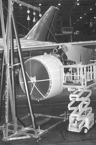
PFASs are used with work from platforms most often when engineering controls are not functional—usually due to restriction of the work process. They are also used with work from aircraft surfaces because of the logistical difficulties associated with engineering controls. The most challenging aspects of PFASs and aircraft surface work are the fall distance with respect to personnel mobility and the added weight to the aircraft structure to support the system. The weight issue may be eliminated by designing the system to attach to the facility around the aircraft surface, rather than the aircraft structure; however, this also limits fall protection capability to that one facility location. Figure 2 shows a portable gantry used for providing a PFAS. PFASs are used more extensively in maintenance operations than manufacturing, but are used during certain manufacturing situations.
Figure 2. Engine gantry providing fall protection for aircraft engine worker.
Courtesy of The Boeing Company
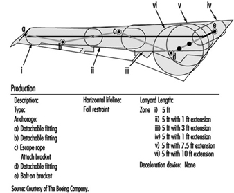
A fall restraint system (FRS) is a system designed so that the individual is prevented from falling over the edge. FRSs are very similar to PFASs in that all the components are the same; however, the FRSs restrict the individual’s range of movement such that the individual cannot reach close enough to the edge of the surface to fall over. FRSs are the preferred evolution of PPE systems for both manufacturing and maintenance operations, because they prevent any fall-related injury and they eliminate the need for a rescue process. They are not extensively used in either work from platforms or aircraft surfaces, because of the challenges of designing the system so that personnel have the mobility needed to perform the work process, but are restricted from reaching the edge of the surface. These systems decrease the weight/efficiency issue with work from aircraft surfaces, because FRSs do not require the strength that a PFAS requires. At the time of printing, only one aircraft type (the Boeing 747) had an airframe-based FRS available. See figure 3 and figure 4.
Figure 3. Boeing 747 wing lanyard system.

Courtesy of The Boeing Company
Figure 4. Boeing 747 wing lanyard system fall protection zones.
Courtesy of The Boeing Company
A horizontal lifeline attaches to permanent fittings on the wing surface, creating six fall protection zones. Employees connect a 1.5 m lanyard to D-rings or strap extensions that slide along the horizontal lifeline in zones i through iv, and are fixed in zones v and vi. The system allows access only to the edge of the wing, preventing the possibility of falling from the wing surface.
Procedural Controls
Procedural controls are used when both engineering controls and PPE are either ineffective or impractical. This is the least preferred method of protection, but is effective if managed properly. Procedural controls consist of designating the work surface as a restricted area for only those individuals that are required to enter during that specific maintenance process. Fall protection is achieved through very aggressive written procedures covering hazard exposure identification, communication and individual actions. These procedures mitigate the exposure as best as possible under the circumstances of the situation. They must be site specific and must address the specific hazards of that situation. These are very seldom used for work from platforms in either manufacturing or maintenance, but they are used for maintenance work from aircraft surfaces.
Aircraft Engine Manufacturing
The manufacture of aircraft engines, whether piston or jet, involves the conversion of raw materials into extremely reliable precision machines. The highly stressed operating environments associated with air transport require the use of a broad range of high-strength materials. Both conventional and unique manufacturing methods are utilized.
Construction Materials
Aircraft engines are primarily constructed of metallic components, although recent years have seen the introduction of plastic composites for certain parts. Various aluminium and titanium alloys are used where strength and light weight are of primary importance (structural components, compressor sections, engine frames). Chromium, nickel and cobalt alloys are used where resistance to high temperature and corrosion are required (combustor and turbine sections). Numerous steel alloys are used in intermediate locations.
Since weight minimization on aircraft is a critical factor in reducing life-cycle costs (maximizing payload, minimizing fuel consumption), advanced composite materials have recently been introduced as light-weight replacements for aluminium, titanium and some steel alloys in structural parts and ductwork where high temperatures are not experienced. These composites consist primarily of polyimide, epoxy and other resin systems, reinforced with woven fibreglass or graphite fibres.
Manufacturing Operations
Virtually every common metalworking and machining operation is used in aircraft engine manufacture. This includes hot forging (airfoils, compressor disks), casting (structural components, engine frames), grinding, broaching, turning, drilling, milling, shearing, sawing, threading, welding, brazing and others. Associated processes involve metal finishing (anodizing, chromating and so on), electroplating, heat treating and thermal (plasma, flame) spraying. The high strength and hardness of the alloys used, combined with their complex shapes and precision tolerances, necessitate more challenging and rigorous machining requirements than other industries.
Some of the more unique metalworking processes include chemical and electrochemical milling, electro-discharge machining, laser drilling and electron-beam welding. Chemical and electrochemical milling involve the removal of metal from large surfaces in a manner which retains or creates a contour. The parts, depending upon their specific alloy, are placed in a highly concentrated controlled acid, caustic or electrolyte bath. Metal is removed by the chemical or electrochemical action. Chemical milling is often used after forging of airfoils to bring wall thicknesses into specification while maintaining the contour.
Electro-discharge machining and laser drilling are typically used for making small-diameter holes and intricate contours in hard metals. Many such holes are required in combustor and turbine components for cooling purposes. Metal removal is accomplished by high-frequency thermo-mechanical action of electro-spark discharges. The process is carried out in a dielectric mineral oil bath. The electrode serves as the reverse image of the desired cut.
Electron-beam welding is used to join parts where deep weld penetration is required in hard-to-reach geometries. The weld is generated by a focused, accelerated beam of electrons within a vacuum chamber. The kinetic energy of the electrons striking the work-piece is transformed into heat for welding.
Composite plastic fabrication involves either “wet” lay-up techniques or the use of pre-impregnated cloths. With wet lay-up, the viscous uncured resin mixture is spread over a tooling form or mould by either spraying or brushing. The fibre reinforcement material is manually laid into the resin. Additional resin is applied to obtain uniformity and contour with the tooling form. The completed lay-up is then cured in an autoclave under heat and pressure. Pre-impregnated materials consist of semi-rigid, ready-to-use, partially-cured sheets of resin-fibre composites. The material is cut to size, manually moulded to the contours of the tooling form and cured in an autoclave. Cured parts are conventionally machined and assembled into the engine.
Inspection and Testing
In order to assure the reliability of aircraft engines, a number of inspection, testing and quality-control procedures are performed during the fabrication and on the final product. Common non-destructive inspection methods include radiographic, ultrasonic, magnetic particle and fluorescent penetrant. They are used to detect any cracks or internal flaws within the parts. Assembled engines are usually tested in instrumented test cells prior to customer delivery.
Health and Safety Hazards and Their Control Methods
Health hazards associated with aircraft engine manufacture are primarily related to the toxicity of the materials used and their potential for exposure. Aluminium, titanium and iron are not considered significantly toxic, while chromium, nickel and cobalt are more problematic. Certain compounds and valence states of the latter three metals have indicated carcinogenic properties in humans and animals. Their metallic forms are generally not considered as toxic as their ionic forms, typically found in metal finishing baths and paint pigments.
In conventional machining, most operations are performed using coolants or cutting fluids which minimize the generation of airborne dust and fumes. With the exception of dry grinding, the metals usually do not present inhalation hazards, although there is concern about the inhalation of coolant mists. A fair amount of grinding is performed, particularly on jet engine parts, to blend contours and bring airfoils into their final dimensions. Small, hand-held grinders are typically used. Where such grinding is performed on chromium-, nickel- or cobalt-based alloys, local ventilation is required. This includes down-draft tables and self-ventilating grinders. Dermatitis and noise are additional health hazards associated with conventional machining. Employees will have varying degrees of skin contact with coolants and cutting fluids in the course of fixing, inspecting and removing parts. Repeated skin contact may manifest itself in various forms of dermatitis in some employees. Generally, protective gloves, barrier creams and proper hygiene will minimize such cases. High noise levels are often present when machining thin-walled, high-strength alloys, due to tool chatter and part vibration. This can be controlled to an extent through more rigid tooling, dampening materials, modifying machining parameters and maintaining sharp tools. Otherwise, PPE (e.g., ear muffs, plugs) is required.
Safety hazards associated with conventional machining operations mainly involve potential for physical injuries due to the point-of-operation, fixing and power transmission drive movements. Control is accomplished through such methods as fixed guards, interlocked access doors, light curtains, pressure-sensitive mats and employee training and awareness. Eye protection should always be used around machining operations for protection from flying chips, particles and splashes of coolants and cleaning solvents.
Metal-finishing operations, chemical milling, electrochemical milling and electroplating involve open surface tank exposures to concentrated acids, bases and electrolytes. Most of the baths contain high concentrations of dissolved metals. Depending upon bath operating conditions and composition (concentration, temperature, agitation, size), most will require some form of local ventilation to control airborne levels of gases, vapours and mists. Various lateral, slot-type hood designs are commonly used for control. Ventilation designs and operating guidelines for different types of baths are available through technical organizations such as the American Conference of Governmental Industrial Hygienists (ACGIH) and the American National Standards Institute (ANSI). The corrosive nature of these baths dictates the use of eye and skin protection (splash goggles, face shields, gloves, aprons and so on) when working around these tanks. Emergency eyewashes and showers must also be available for immediate use.
Electron-beam welding and laser drilling present radiation hazards to workers. Electron-beam welding generates secondary x-ray radiation (bremsstrahlung effect). In a sense, the welding chamber constitutes an inefficient x-ray tube. It is critical that the chamber be constructed of material or contain shielding which will attenuate the radiation to the lowest practical levels. Lead shielding is often used. Radiation surveys should be periodically performed. Lasers present ocular and skin (thermal) hazards. Also, there is potential for exposure to the metal fumes produced by the evaporation of the base metal. Beam hazards associated with laser operations should be isolated and contained, where possible, within interlocked chambers. A comprehensive programme should be rigorously followed. Local ventilation should be provided where metal fumes are generated.
The major hazards related to the fabrication of composite plastic parts involve chemical exposure to unreacted resin components and solvents during wet lay-up operations. Of particular concern are aromatic amines used as reactants in polyimide resins and hardeners in epoxy resin systems. A number of these compounds are confirmed or suspected human carcinogens. They also exhibit other toxic effects. The highly reactive nature of these resin systems, particularly epoxies, gives rise to skin and respiratory sensitization. Control of hazards during wet lay-up operations should include local ventilation and extensive use of personal protective equipment to prevent skin contact. Lay-up operations using pre-impregnated sheets usually do not present airborne exposures, but skin protection should be used. Upon curing, these parts are relatively inert. They no longer present the hazards of their constituent reactants. Conventional machining of the parts, though, can produce nuisance dusts of an irritant nature, associated with the composite reinforcement materials (fibreglass, graphite). Local ventilation of the machining operation is often required.
Health hazards associated with test operations usually involve radiation (x or gamma rays) from radiographic inspection and noise from final product tests. Radiographic operations should include a comprehensive radiation safety programme, complete with training, badge monitoring and periodic surveys. Radiographic inspection chambers should be designed with interlocked doors, operating lights, emergency shut-offs and proper shielding. Test areas or cells where assembled products are tested should be acoustically treated, particularly for jet engines. Noise levels at the control consoles should be controlled to below 85 dBA. Provisions should also be made to prevent any build-up of exhaust gases, fuel vapours or solvents in the test area.
In addition to the aforementioned hazards related to specific operations, there are several others worthy of note. They include exposure to cleaning solvents, paints, lead and welding operations. Cleaning solvents are used throughout manufacturing operations. There has been a recent trend away from the use of chlorinated and fluorinated solvents to aqueous, terpine, alcohol and mineral spirit types due to toxicity and ozone depletion effects. Although the latter group may tend to be more environmentally acceptable, they often present fire hazards. Quantities of any flammable or combustible solvents should be limited in the workplace, used only from approved containers and with adequate fire protection in place. Lead is sometimes used in airfoil forging operations as a die lubricant. If so, a comprehensive lead control and monitoring programme should be in effect due to lead’s toxicity. Many types of conventional welding are used in manufacturing operations. Metal fumes, ultraviolet radiation and ozone exposures need to be evaluated for such operations. The need for controls will depend upon the specific operating parameters and metals involved.
Controls and Health Effects
There is a growing market demand for the aerospace industry to decrease product development flow time while at the same time utilizing materials that meet increasingly stringent, and sometimes contradictory, performance criteria. Accelerated product testing and production may cause material and process development to outpace the parallel development of environmental health technologies. The result may be products which have been performance tested and approved but for which there exist insufficient data on health and environmental impact. Regulations such as the Toxic Substance Control Act (TSCA) in the United States require (1) testing of new materials; (2) the development of prudent lab practices for research and development testing; (3) restrictions on the import and export of certain chemicals; and
(4) monitoring of health, safety and environmental studies as well as company records for significant health effects from chemical exposures.
The increased use of material safety data sheets (MSDSs) has helped provide health professionals with the information required to control chemical exposures. However, complete toxicological data exist for only a few hundred of the thousands of materials in use, providing a challenge to industrial hygienists and toxicologists. To the extent feasible, local exhaust ventilation and other engineering controls should be used to control exposure, particularly when poorly understood chemicals or inadequately characterized contaminant generation rates are involved. Respirators can play a secondary role when supported by a well-planned and rigorously enforced respiratory protection management programme. Respirators and other personal protective equipment must be selected to offer fully adequate protection without producing undue discomfort to workers.
Hazard and control information must be effectively communicated to employees prior to a product’s introduction into the work area. Oral presentation, bulletins, videos or other means of communication may be used. The method of communication is important to the success of any workplace chemical introduction. In aerospace manufacturing areas, employees, materials and work processes change frequently. Hazard communication must therefore be a continuous process. Written communications are not likely to be effective in this environment without the support of more active methods such as crew meetings or video presentations. Provisions should always be made for responding to worker questions.
Extremely complex chemical environments are characteristic of airframe manufacturing facilities, particularly assembly areas. Intensive, responsive and well-planned industrial hygiene efforts are required to recognize and characterize hazards associated with the simultaneous or sequential presence of large numbers of chemicals, many of which may not have been adequately tested for health effects. The hygienist must be wary of contaminants released in physical forms not anticipated by the suppliers, and therefore not listed on MSDSs. For example, the repeated application and removal of strips of partially cured composite materials may release solvent-resin mixtures as an aerosol that will not be effectively measured using vapour-monitoring methods.
The concentration and combinations of chemicals may also be complex and highly variable. Delayed work performed out of normal sequence may result in hazardous materials being used without proper engineering controls or adequate personal protective measures. The variations in work practices between individuals and the size and configuration of different airframes may have a significant impact on exposures. Variations in solvent exposures among individuals performing wing tank cleaning have exceeded two orders of magnitude, due in part to the effects of body size on the flow of dilution air in extremely confined areas.
Potential hazards should be identified and characterized, and necessary controls implemented, before materials or processes enter the workplace. Safe usage standards must also be developed, established and documented with mandatory compliance before work begins. Where information is incomplete, it is appropriate to assume the highest reasonably expected risk and to provide appropriate protective measures. Industrial hygiene surveys should be performed at regular and frequent intervals to ensure that controls are adequate and working reliably.
The difficulty of characterizing aerospace workplace exposures necessitates close cooperation between hygienists, clinicians, toxicologists and epidemiologists (see table 1). The presence of a very well informed workforce and management cadre is also essential. Worker reporting of symptoms should be encouraged, and supervisors should be trained to be alert to signs and symptoms of exposure. Biological exposure monitoring may serve as an important supplement to air monitoring where exposures are highly variable or where dermal exposure may be significant. Biological monitoring can also be used to determine whether controls are effective in reducing employee uptake of contaminants. Analysis of medical data for patterns of signs, symptoms and complaints should be performed routinely.
Table 1. Technological development requirements for health, safety and environmental control for new processes and materials.
| Parameter |
Technological requirement |
| Airborne levels of contaminants |
Analytical methods for chemical quantification Air monitoring techniques |
| Potential health impact | Acute and chronic toxicology studies |
| Environmental fate | Bioaccumulation and biodegradation studies |
| Waste characterization | Chemical compatibility test Bioassays |
Paint hangars, aircraft fuselages and fuel tanks may be served by very high volume exhaust systems during intensive painting, sealing and cleaning operations. Residual exposures and the inability of these systems to direct air flow away from workers usually require the supplemental use of respirators. Local exhaust ventilation is required for smaller painting, metal treating and solvent cleaning operations, for laboratory chemical work and for some plastics lay-up work. Dilution ventilation is usually adequate only in areas with minimal chemical usage or as a supplement to local exhaust ventilation. Significant air exchanges during winter can result in excessively dry interior air. Poorly designed exhaust systems which direct excessive cool air flow over workers’ hands or backs in small parts assembly areas may worsen hand, arm and neck problems. In large, complex manufacturing areas, attention must be paid to properly locating ventilation exhaust and intake points to avoid re-entraining contaminants.
Precision manufacturing of aerospace products requires clear, organized and well controlled work environments. Containers, barrels and tanks containing chemicals must be labelled as to the potential hazards of the materials. First aid information must be readily available. Emergency response and spill control information also must be available on the MSDS or similar data sheet. Hazardous work areas must be placarded and access controlled and verified.
Health Effects of Composite Materials
Airframe manufacturers, in both the civilian and defence sectors, have come to rely increasingly on composite materials in the construction of both interior and structural components. Generations of composite materials have been increasingly integrated into production throughout the industry, particularly in the defence sector, where they are valued for their low radar reflectivity. This rapidly developing manufacturing medium typifies the problem of design technology outpacing public health efforts. Specific hazards of the resin or fabric component of the composite prior to combination and resin cure differs from the hazards of cured materials. Additionally, partially cured materials (pre-pregs) may continue to preserve the hazard characteristics of the resin components during the various steps leading to producing a composite part (AIA 1995). Toxicological considerations of major resin categories are provided in table 2.
Table 2. Toxicological considerations of major components of resins utilized in aerospace composite materials.1
| Resin type | Components 2 | Toxicological consideration |
| Epoxy | Amine curing agents, epichlorohydrin | Sensitizer, suspect carcinogen |
| Polyimide | Aldehyde monomer, phenol | Sensitizer, suspect carcinogen, systemic* |
| Phenolic | Aldehyde monomer, phenol | Sensitizer, suspect carcinogen, systemic* |
| Polyester | Styrene, dimethylaniline | Narcosis, central nervous system depression, cyanosis |
| Silicone | Organic siloxane, peroxides | Sensitizer, irritant |
| Thermoplastics** | Polystyrene, polyphenylene sulphide | Systemic*, irritant |
1 Examples of typical components of the uncured resins are provided. Other chemicals of diverse toxicological nature may be present as curing agents, diluents and additives.
2 Applies primarily to components of wet resin prior to reaction. Varying amounts of these materials are present in the partially cured resin, and trace quantities in the cured materials.
* Systemic toxicity, indicating effects produced in several tissues.
** Thermoplastics included as separate category, in that breakdown products listed are created during moulding operations when the polymerized starting material is heated.
The degree and type of hazard posed by composite materials depends primarily on the specific work activity and degree of resin cure as the material moves from a wet resin/fabric to the cured part. Release of volatile resin components may be significant prior to and during initial reaction of resin and curing agent, but may also occur during the processing of materials which go through more than one level of cure. The release of these components tends to be greater in elevated temperature conditions or in poorly ventilated work areas and may range from trace to moderate levels. Dermal exposure to the resin components in the pre-cure state is often an important part of total exposure and therefore should not be neglected.
Off-gassing of resin degradation products may occur during various machining operations which create heat at the surface of the cured material. These degradation products have yet to be fully characterized, but tend to vary in chemical structure as a function of both temperature and resin type. Particles may be generated by machining of cured materials or by cutting pre-pregs which contain residues of resin materials which are released when the material is disturbed. Exposure to gases produced by oven cure has been noted where, through improper design or faulty operation, autoclave exhaust ventilation fails to remove these gases from the work environment.
It should be noted that dusts created by new fabric materials containing fibreglass, kevlar, graphite or boron/metal oxide coatings are generally considered to be capable of producing mild to moderate fibrogenic reaction; so far we have been unable to characterize their relative potency. Additionally, information on the relative contribution of fibrogenic dusts from various machining operations is still under investigation. The various composite operations and hazards have been characterized (AIA 1995) and are listed in table 3.
Table 3. Hazards of chemicals in the aerospace industry.
| Chemical agent | Sources | Potential disease |
| Metals | ||
| Beryllium dust | Machining beryllium alloys | Skin lesions, acute or chronic lung disease |
| Cadmium dust, mist | Welding, burning, spray painting | Delayed acute pulmonary oedema, kidney damage |
| Chromium dust/mist/fumes | Spraying/sanding primer, welding | Cancer of the respiratory tract |
| Nickel | Welding, grinding | Cancer of the respiratory tract |
| Mercury | Laboratories, engineering tests | Central nervous system damage |
| Gases | ||
| Hydrogen cyanide | Electroplating | Chemical asphyxiation, chronic effects |
| Carbon monoxide | Heat treating, engine work | Chemical asphyxiation, chronic effects |
| Oxides of nitrogen | Welding, electroplating, pickling | Delayed acute pulmonary oedema, permanent lung damage (possible) |
| Phosgene | Welding decomposition of solvent vapour | Delayed acute pulmonary oedema, permanent lung damage (possible) |
| Ozone | Welding, high-altitude flight | Acute and chronic lung damage, cancer of the respiratory tract |
| Organic compounds | ||
| Aliphatic | Machine lubricants, fuels, cutting fluids | Follicular dermatitis |
| Aromatic, nitro and amino | Rubber, plastics, paints, dyes | Anaemia, cancer, skin sensitization |
| Aromatic,other | Solvents | Narcosis, liver damage, dermatitis |
| Halogenated | Depainting, degreasing | Narcosis, anaemia, liver damage |
| Plastics | ||
| Phenolics | Interior components, ducting | Allergic sensitization, cancer (possible) |
| Epoxy (amine hardeners) | Lay-up operations | Dermatitis, allergic sensitization, cancer |
| Polyurethane | Paints, internal components | Allergic sensitization, cancer (possible) |
| Polyimide | Structural components | Allergic sensitization, cancer (possible) |
| Fibrogenic dusts | ||
| Asbestos | Military and older aircraft | Cancer, asbestosis |
| Silica | Abrasive blasting, fillers | Silicosis |
| Tungsten carbide | Precision tool grinding | Pneumoconiosis |
| Graphite, kevlar | Composite machining | Pneumoconiosis |
| Benign dusts (possible) | ||
| Fibreglass | Insulating blankets, interior components | Skin and respiratory irritation, chronic disease (possible) |
| Wood | Mock-up and model making | Allergic sensitization, respiratory cancer |
Environmental and Public Health Issues
Aerospace industries have been significantly affected by the enormous growth in environmental and community noise regulations passed primarily in the United States and Europe since the 1970s. Legislation such as the Clean Water Act, the Clean Air Act and the Resource Conservation and Recovery Act in the United States and companion Directives in the European Union have resulted in voluminous local regulations to meet environmental quality objectives. These regulations typically enforce the use of best available technology, whether new materials or processes or end of stack control equipment. Additionally, universal issues such as ozone depletion and global warming are forcing changes to traditional operations by banning chemicals such as chlorofluorocarbons entirely unless exceptional conditions exist.
Early legislation had little impact on aerospace operations until the 1980s. The continued growth of the industry and the concentration of operations around airports and industrialized areas made regulation attractive. The industry underwent a revolution in terms of programmes required to track and manage toxic emissions to the environment with the intent to ensure safety. Wastewater treatment from metal finishing and aircraft maintenance became standard at all large facilities. Hazardous waste segregation, classification, manifesting and, later, treatment prior to disposal were instituted where rudimentary programmes had previously existed. Clean-up programmes at disposal sites became major economic issues for many companies as costs rose to many millions at each site. In the later 1980s and early 1990s, air emissions, which constitute as much as 80% or more of the total emissions from aircraft manufacturing and operation, became the focus of regulation. The International Civil Aviation Organization (ICAO) adopted engine emission standards as early as 1981 (ICAO 1981).
Chemical emissions regulations affect essentially all chemical processing, engine and auxiliary power unit, fuelling and ground service vehicle operations. In Los Angeles, for example, ground-level ozone and carbon monoxide reductions to achieve Clean Air Act standards could require a reduction of 50% of flight operations at Los Angeles International Airport by the year 2005 (Donoghue 1994). Emissions there will be tracked daily to ensure limits on total emissions of volatile organic compounds and carbon monoxide are below the overall total permitted. In Sweden, a tax has been levied on aircraft carbon dioxide emissions due to their global warming potential. Similar regulations in some regions have resulted in a near total elimination of vapour degreasing using chlorinated solvents such as trichloroethane due to the historically high levels of emissions from open-topped degreasers and the ozone depleting potential and toxicity of 1,1,1 trichloroethane.
Perhaps the most broad-based regulation yet imposed is the Aerospace National Emission Standard for Hazardous Air Pollutants (NESHAP) of 1995, promulgated by the United States Environmental Protection Agency under the Clean Air Act Amendments of 1990. This regulation requires all aerospace operations to comply with the average of the best 12% of the current United States control practices to reduce the emission of pollutants from the processes of greatest emissions. The standard requires compliance by September 1998. The processes and materials most affected are manual wipe and flush cleaning, primers and topcoats, paint removal and chemical milling maskants. The regulation allows process change or control and charges local authorities with enforcement of material, equipment, work practice and record-keeping requirements. The significance of these rules is the imposition of the best practices with little regard to cost on every aerospace manufacturer. They force a comprehensive change to low vapour pressure solvent cleaning materials and to coatings low in solvent content, as well as application equipment technology as shown in table 1. Some exceptions were made where product safety or personnel safety (due to fire hazard and so on) would be compromised.
Table 1. Summary of the United States NESHAP in manufacturing and reworking facilities.
| Process | Requirements1 |
| Manual wipe cleaning of aerospace components |
Maximum composite pressure of 45 mmHg at 20 °C or use of specific preferred cleaners Exemptions for confined spaces, work near energized systems, etc. Immediate enclosure of wipers to contain further evaporation |
| Flush cleaning with VOCs2 or HAPs3 containing materials | Collection and containment of fluids |
| Application of primers and topcoats | Use of high transfer efficiencyequipment4 |
| Primer HAP content less water | 350 g/l of primer as applied on average5 |
| Top coat HAP content water | 420 g/l of topcoat as applied on average5 |
| Exterior surface paint removal |
Zero HAP chemicals, mechanical blast, high-intensity light6. Allowance for 6 assembled aircraft to be depainted per site/year with HAP-containing chemicals |
| Coatings containing inorganic HAPs | High efficiency control of particulate emissions |
| Chemical milling mask HAP content less water | 160 g/l of material as applied or a high-efficiency vapour collection and control system |
| Overspray from coating operations with HAP | Multistage particulate filter |
| Air pollution control equipment | Minimum acceptable efficiencies plus monitoring |
| Spray gun cleaning | No atomization of cleaning solvent, provisions to capture waste |
1 Considerable record keeping, inspection and other requirements apply, not listed here.
2 Volatile organic compounds. These have been shown to be photochemical reactive and precursors to ground-level ozone formation.
3 Hazardous air pollutants. These are 189 compounds listed by the US Environmental Protection Agency as toxic.
4 Listed equipment includes electrostatic or high-volume, low-pressure (HVLP) spray guns.
5 Specialty coatings and other low-emission processes excluded.
6 Touch-up allowed using 26 gallons per aircraft per year of HAP-containing remover (commercial), or 50 gallons per year (military).
Source: US EPA Regulation: 40 CFR Part 63.
Summaries of typical chemical hazards and emission-control practices due to the impact of environmental regulations on manufacturing and maintenance operations in the United States are provided in table 2 and table 3 respectively. European regulations have for the most part not kept pace in the area of toxic air emissions, but have placed greater emphasis on the elimination of toxins, such as cadmium, from the products and the accelerated phase-out of ozone depleter compounds. The Netherlands require operators to justify the use of cadmium as essential for flight safety, for example.
Table 2. Typical chemical hazards of manufacturing processes.
| Common processes | Type of emission | Chemicals or hazards |
| Coatings, including temporary protective coatings, mask and paints |
Overspray of solids and evaporation of solvents
Solid waste, (e.g., wipers)
|
Volatile organic compouds (VOCs) including methyl ethyl ketone, toluene, xylenes Ozone-depleting compounds (ODCs) (chlorofluorocarbons, trichloroethane and others) Organic toxins including tricholorethane, xylene, toluene Inorganic toxins including cadmium, chromates, lead VOCs or toxins as above |
| Solvent cleaning |
Evaporation of solvents Solid waste (wipers) Liquid waste |
VOCs, ozone depletersor toxins VOCs or toxins Waste solvent (VOCs) and/or contaminated water |
| Paint removal |
Evaporation or entrainment of solvents
Corrosive liquid waste Dust, heat, light |
VOCs such as xylene, toluene, methyl ethyl ketone Organic toxins (methylene chloride, phenolics) Heavy metals (chromates) Caustics and acids including formic acid Toxic dust (blasting), heat (thermal stripping) and light |
| Anodizing aluminium |
Ventilation exhaust Liquid waste |
Acid mist Concentrated acid usually chromic, nitric and hydrofluoric |
| Plating hard metals |
Ventilation exhaust Rinsewaters |
Heavy metals, acids, complexed cyanides Heavy metals, acids, complexed cyanides |
| Chemical milling | Liquid waste | Caustics and heavy metals, other metals |
| Sealing |
Evaporated solvent Solid waste |
VOCs Heavy metals, trace amounts of toxic organics |
| Alodining (conversion coating) |
Liquid waste Solid waste |
Chromates, possibly complexed cyanide Chromates, oxidizers |
| Corrosion-inhibiting ompounds | Particulates, solid waste | Waxes, heavy metals and toxic organics |
| Composite fabrication | Solid waste | Uncured volatiles |
| Vapour degreasing | Escaped vapour | Tricholorethane, trichoroethylene, perchloroethylene |
| Aqueous degreasing | Liquid waste | VOCs, silicates, trace metals |
Table 3. Typical emission-control practices.
| Processes | Air emissions | Water emissions | Land emissions |
| Coating: overspray | Emission control equipment1 for overspray (VOCs and solid particulate) | Onsite pretreatment and monitoring | Treat and landfill3 paint-booth waste. Incinerate flammables and landfill ash. Recycle solvents where possible. |
| Solvent cleaning with VOCs | Emission controls2 and/or material substitution | Onsite pretreatment and monitoring | Incinerate and landfill used wipers |
| Solvent cleaning with ODCs | Substitution due to ban on ODCs production | None | None |
| Solvent cleaning with toxins | Substitution | Onsite pretreatment and monitoring | Treat to reduce toxicity4 and landfill |
| Paint removal | Emission controls or substitution with non-HAP or mechanical methods | Onsite pretreatment and monitoring | Treatment sludge stabilized and landfilled |
| Anodizing aluminium, plating hard metals, chemical milling and immersion conversion coating (Alodine) | Emission control (scrubbers) and/or substitution in some cases | Onsite pretreatment of rinsewaters. Acid and caustic concentrates treated on or off site | Treatment sludge stabilized and landfilled. Other solid waste treated and landfilled |
| Sealing | Usually none required | Usually none required | Incinerate and landfill used wipers |
| Corrosion-inhibiting compounds | Ventilation filtered | Usually none required | Wipers, residual compound and paint-booth filters5 treated and landfilled |
| Vapour degreasing | Chillers to recondense vapours Enclosed systems, or Activated carbon collection | Degreasing solvent separation from wastewater | Toxic degreasing solvent recycled, residual treated and landfilled |
| Aqueous degreasing | Usually none required | Onsite pretreatment and monitoring | Pretreatment sludge managed as hazardous waste |
1 Most aerospace facilities are required to own an industrial wastewater pretreatment facility. Some may have full treatment.
2 Control efficiency usually must be greater than 95% removal/destruction of incoming concentrations. Commonly 98% or greater is achieved by activated carbon or thermal oxidation units.
3 Strict regulations on landfilling specify treatment and landfill construction and monitoring.
4 Toxicity is measured by bioassay and/or leaching tests designed to predict results in solid waste landfills.
5 Usually filtered paint booths. Work done out of sequence or touch up, etc. is usually exempt due to practical considerations.
Noise regulations have followed a similar course. The United States Federal Aviation Administration and the International Civil Aviation Organization have set aggressive targets for the improvement of jet engine noise reduction (e.g., the United States Airport Noise and Capacity Act of 1990). Airlines are faced with the option of replacing older aircraft such as the Boeing 727 or McDonnell Douglas DC-9 (Stage 2 aircraft as defined by the ICAO) with new generation airplanes, re-engining or retrofitting these aircraft with “hush” kits. Elimination of noisy Stage 2 aircraft is mandated by 31 December 1999 in the United States, when Stage 3 rules take effect.
Another hazard posed by aerospace operation is the threat of falling debris. Items such as waste, aircraft parts and satellites descend with varying degrees of frequency. The most common in terms of frequency is the so-called blue ice which results when leaking toilet system drains allow waste to freeze outside the aircraft and then separate and fall. Aviation authorities are considering rules to require additional inspection and correction of leaking drains. Other hazards such as satellite debris may occasionally be hazardous (e.g., radioactive instruments or power sources), but present extremely low risk to the public.
Most companies have formed organizations to address emission reduction. Goals for environmental performance are established and policies are in place. Management of the permits, safe material handling and transportation, disposal and treatment require engineers, technicians and administrators.
Environmental engineers, chemical engineers and others are employed as researchers and administrators. In addition, programmes exist to help remove the source of chemical and noise emissions within the design or the process.
" DISCLAIMER: The ILO does not take responsibility for content presented on this web portal that is presented in any language other than English, which is the language used for the initial production and peer-review of original content. Certain statistics have not been updated since the production of the 4th edition of the Encyclopaedia (1998)."