There seem to be as many potential hazards created by moving machine parts as there are different types of machines. Safeguards are essential to protect workers from needless and preventable machinery-related injuries. Therefore, any machine part, function or process which may cause injury should be safeguarded. Where the operation of a machine or accidental contact with it can injure the operator or others in the vicinity, the hazard must be either controlled or eliminated.
Mechanical Motions and Actions
Mechanical hazards typically involve dangerous moving parts in the following three basic areas:
- the point of operation, that point where work is performed on the material, such as cutting, shaping, punching, stamping, boring or forming of stock
- power transmission apparatus, any components of the mechanical system which transmit energy to the parts of the machine performing the work. These components include flywheels, pulleys, belts, connecting rods, couplings, cams, spindles, chains, cranks and gears
- other moving parts, all parts of the machine which move while the machine is working, such as reciprocating, rotating and transversely moving parts, as well as feed mechanisms and auxiliary parts of the machine.
A wide variety of mechanical motions and actions which may present hazards to workers include the movement of rotating members, reciprocating arms, moving belts, meshing gears, cutting teeth and any parts that impact or shear. These different types of mechanical motions and actions are basic to nearly all machines, and recognizing them is the first step toward protecting workers from the hazards they may present.
Motions
There are three basic types of motion: rotating, reciprocating and transverse.
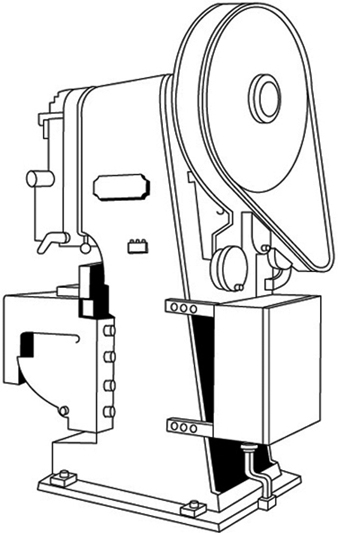
Rotating motion can be dangerous; even smooth, slowly rotating shafts can grip clothing and force an arm or hand into a dangerous position. Injuries due to contact with rotating parts can be severe (see figure 1).
Figure 1. Mechanical punch press
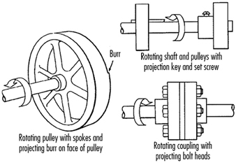
Collars, couplings, cams, clutches, flywheels, shaft ends, spindles and horizontal or vertical shafting are some examples of common rotating mechanisms which may be hazardous. There is added danger when bolts, nicks, abrasions and projecting keys or set screws are exposed on rotating parts on machinery, as shown in figure 2.
Figure 2. Examples of hazardous projections on rotating parts
In-running nip points are created by rotating parts on machinery. There are three main types of in-running nip points:
- Parts with parallel axes can rotate in opposite directions. These parts may be in contact (thereby producing a nip point) or in close proximity to each other, in which case the stock fed between the rolls produces the nip points. This danger is common on machinery with intermeshing gears, rolling mills and calenders, as shown in figure 3.
- Another type of nip point is created between rotating and tangentially moving parts, such as the point of contact between a power transmission belt and its pulley, a chain and a sprocket, or a rack and pinion, as shown in figure 4.
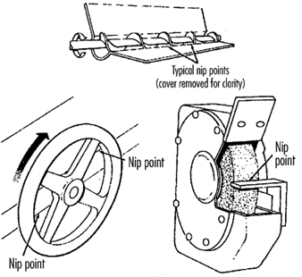
- Nip points can also occur between rotating and fixed parts which create a shearing, crushing or abrading action. Examples include handwheels or flywheels with spokes, screw conveyors or the periphery of an abrasive wheel and an incorrectly adjusted work rest, as shown in figure 5.
Figure 3. Common nip points on rotating parts
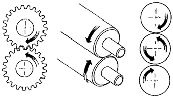
Figure 4. Nip points between rotating elements and parts with longitudinal motions
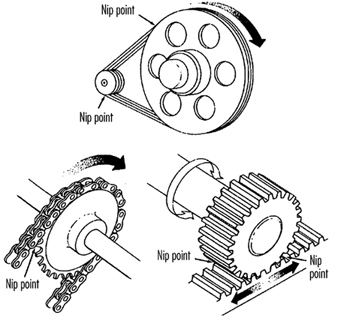
Figure 5. Nip points between rotating machine components
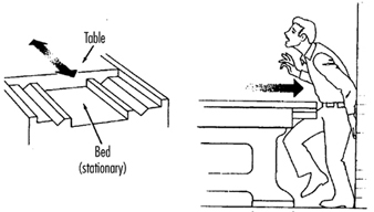
Reciprocating motions may be hazardous because during the back-and-forth or up-and-down motion, a worker may be struck by or caught between a moving part and a stationary part. An example is shown in figure 6.
Figure 6. Hazardous reciprocating motion
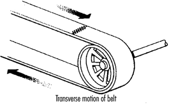
Transverse motion (movement in a straight, continuous line) creates a hazard because a worker may be struck or caught in a pinch or shear point by a moving part. An example of transverse motion is shown in figure 7.
Figure 7. Example of transverse motion
Actions
There are four basic types of action: cutting, punching, shearing and bending.
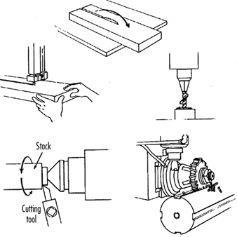
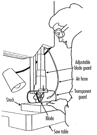
Cutting action involves rotating, reciprocating or transverse motion. Cutting action creates hazards at the point of operation where finger, head and arm injuries can occur and where flying chips or scrap material can strike the eyes or face. Typical examples of machines with cutting hazards include band saws, circular saws, boring or drilling machines, turning machines (lathes) and milling machines. (See figure 8.)
Figure 8. Examples of cutting hazards
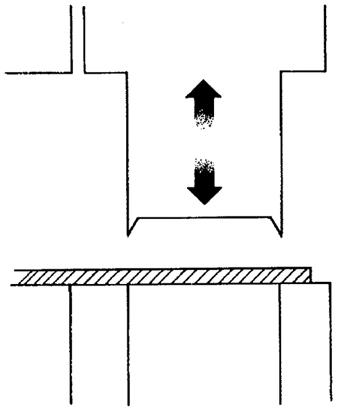
Punching action results when power is applied to a slide (ram) for the purpose of blanking, drawing or stamping metal or other materials. The danger of this type of action occurs at the point of operation where stock is inserted, held and withdrawn by hand. Typical machines which use punching action are power presses and iron workers. (See figure 9.)
Figure 9. Typical punching operation
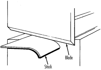
Shearing action involves applying power to a slide or knife in order to trim or shear metal or other materials. A hazard occurs at the point of operation where stock is actually inserted, held and withdrawn. Typical examples of machinery used for shearing operations are mechanically, hydraulically or pneumatically powered shears. (See figure 10.)
Figure 10. Shearing operation
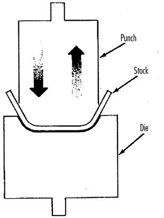
Bending action results when power is applied to a slide in order to shape, draw or stamp metal or other materials. The hazard occurs at the point of operation where stock is inserted, held and withdrawn. Equipment that uses bending action includes power presses, press brakes and tubing benders. (See figure 11.)
Figure 11. Bending operation
Requirements for Safeguards
Safeguards must meet the following minimum general requirements to protect workers against mechanical hazards:
Prevent contact. The safeguard must prevent hands, arms or any part of a worker’s body or clothing from making contact with dangerous moving parts by eliminating the possibility of the operators or other workers placing parts of their bodies near hazardous moving parts.
Provide security. Workers should not be able to easily remove or tamper with the safeguard. Guards and safety devices should be made of durable material that will withstand the conditions of normal use and that are firmly secured to the machine.
Protect from falling objects. The safeguard should ensure that no objects can fall into moving parts and damage the equipment or become a projectile that could strike and injure someone.
Not create new hazards. A safeguard defeats its purpose if it creates a hazard of its own, such as a shear point, a jagged edge or an unfinished surface. The edges of guards, for example, should be rolled or bolted in such a way that they eliminate sharp edges.
Not create interference. Safeguards which impede workers from performing their jobs might soon be overridden or disregarded. If possible, workers should be able to lubricate machines without disengaging or removing safeguards. For example, locating oil reservoirs outside the guard, with a line leading to the lubrication point, will reduce the need to enter the hazardous area.
Safeguard Training
Even the most elaborate safeguarding system cannot offer effective protection unless workers know how to use it and why. Specific and detailed training is an important part of any effort to implement safeguarding against machine-related hazards. Proper safeguarding may improve productivity and enhance efficiency since it may relieve workers’ apprehensions about injury. Safeguard training is necessary for new operators and maintenance or set-up personnel, when any new or altered safeguards are put in service, or when workers are assigned to a new machine or operation; it should involve instruction or hands-on training in the following:
- a description and identification of the hazards associated with particular machines and the specific safeguards against each hazard
- how the safeguards provide protection; how to use the safeguards and why
- how and under what circumstances safeguards can be removed, and by whom (in most cases, repair or maintenance personnel only)
- what to do (e.g., contact the supervisor) if a safeguard is damaged, missing or unable to provide adequate protection.
Methods of Machine Safeguarding
There are many ways to safeguard machinery. The type of operation, the size or shape of stock, the method of handling, the physical layout of the work area, the type of material and production requirements or limitations will help to determine the appropriate safeguarding method for the individual machine. The machine designer or safety professional must choose the most effective and practical safeguard available.
Safeguards may be categorized under five general classifications: (1) guards, (2) devices, (3) separation, (4) operations and (5) other.
Safeguarding with guards
There are four general types of guards (barriers which prevent access to danger areas), as follows:
Fixed guards. A fixed guard is a permanent part of the machine and is not dependent upon moving parts to perform its intended function. It may be constructed of sheet metal, screen, wire cloth, bars, plastic or any other material that is substantial enough to withstand whatever impact it may receive and to endure prolonged use. Fixed guards are usually preferable to all other types because of their relative simplicity and permanence (see table 1).
Table 1. Machine guards
|
Method |
Safeguarding action |
Advantages |
Limitations |
|
Fixed |
· Provides a barrier |
· Suits many specific applications |
· May interfere with visibility |
|
Interlocked |
· Shuts off or disengages power and prevents starting of machine when guard is open; should require the machine to be stopped before the worker can reach into the danger area |
· Provides maximum protection |
· Requires careful adjustment and maintenance |
|
Adjustable |
· Provides a barrier which may be adjusted to facilitate a variety of production operations |
· Can be constructed to suit many specific applications |
· Operator may enter danger area: protection may not be complete at all times |
|
Self-adjusting |
· Provides a barrier which moves according to the size of the stock entering danger area |
· Off-the-shelf guards are commercially available |
· Does not always provide maximum protection |
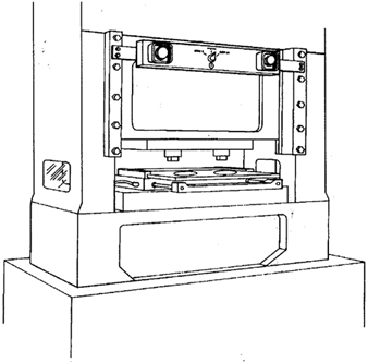
In figure 12, a fixed guard on a power press completely encloses the point of operation. The stock is fed through the side of the guard into the die area, with the scrap stock exiting on the opposite side.
Figure 12. Fixed guard on power press
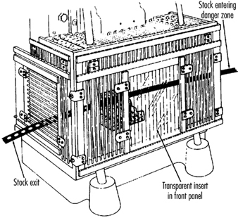
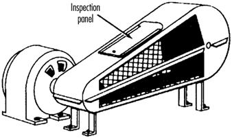
Figure 13 depicts a fixed enclosure guard which shields the belt and pulley of a power transmission unit. An inspection panel is provided on top to minimize the need for removing the guard.
Figure 13. Fixed guard enclosing belts and pulleys
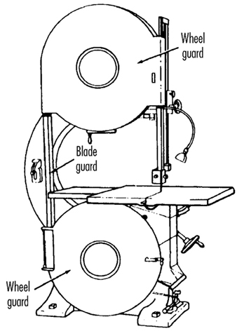
In figure 14, fixed enclosure guards are shown on a bandsaw. These guards protect operators from the turning wheels and moving saw blade. Normally, the only time the guards would be opened or removed would be for a blade change or for maintenance. It is very important that they be securely fastened while the saw is in use.
Figure 14. Fixed guards on band-saw
Interlocked guards. When interlocked guards are opened or removed, the tripping mechanism and/or power automatically shuts off or disengages, and the machine cannot cycle or be started until the interlock guard is back in place. However, replacing the interlock guard should not automatically restart the machine. Interlocked guards may use electrical, mechanical, hydraulic or pneumatic power, or any combination of these. Interlocks should not prevent “inching” (i.e., gradual progressive movements) by remote control, if required.
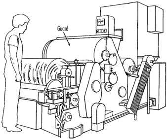
An example of an interlocking guard is shown in figure 15. In this figure, the beater mechanism of a picker machine (used in the textile industry) is covered by an interlocked barrier guard. This guard cannot be raised while the machine is running, nor can the machine be restarted with the guard in the raised position.
Figure 15. Interlocked guard on picker machine
Adjustable guards. Adjustable guards allow flexibility in accommodating various sizes of stock. Figure 16 shows an adjustable enclosure guard on a band-saw.
Figure 16. Adjustable guard on band-saw
Self-adjusting guards. The openings of self-adjusting guards are determined by the movement of the stock. As the operator moves the stock into the danger area, the guard is pushed away, providing an opening which is large enough to admit only the stock. After the stock is removed, the guard returns to the rest position. This guard protects the operator by placing a barrier between the danger area and the operator. The guards may be constructed of plastic, metal or other substantial material. Self-adjusting guards offer different degrees of protection.
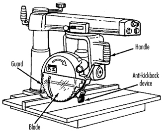
Figure 17 shows a radial-arm saw with a self-adjusting guard. As the blade is pulled across the stock, the guard moves up, staying in contact with the stock.
Figure 17. Self-adjusting guard on radial-arm saw
Safeguarding with devices
Safety devices may stop the machine if a hand or any part of the body is inadvertently placed in the danger area, may restrain or withdraw the operator’s hands from the danger area during operation, may require the operator to use both hands on machine controls simultaneously (thus keeping both hands and body out of danger) or may provide a barrier which is synchronized with the operating cycle of the machine in order to prevent entry to the danger area during the hazardous part of the cycle. There are five basic types of safety devices, as follows:
Presence-sensing devices
Three types of sensing devices which stop the machine or interrupt the work cycle or operation if a worker is within the danger zone are described below:
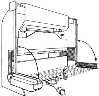
The photoelectric (optical) presence-sensing device uses a system of light sources and controls which can interrupt the machine’s operating cycle. If the light field is broken, the machine stops and will not cycle. This device should be used only on machines which can be stopped before the worker reaches the danger area. Figure 18 shows a photoelectric presence-sensing device used with a press brake. The device may be swung up or down to accommodate different production requirements.
Figure 18. Photoelectric presence-sensing device on press brake
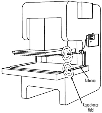
The radio-frequency (capacitance) presence-sensing device uses a radio beam that is part of the control circuit. When the capacitance field is broken, the machine will stop or will not activate. This device should be used only on machines which can be stopped before the worker can reach the danger area. This requires the machine to have a friction clutch or other reliable means for stopping. Figure 19 shows a radio-frequency presence-sensing device mounted on a part-revolution power press.
Figure 19. Radio-frequency presence-sensing device on power saw
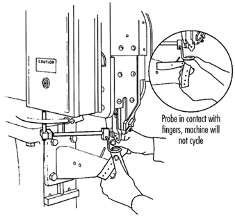
The electro-mechanical sensing device has a probe or contact bar which descends to a predetermined distance when the operator initiates the machine cycle. If there is an obstruction preventing it from descending its full predetermined distance, the control circuit does not actuate the machine cycle. Figure 20 shows an electro-mechanical sensing device on an eyeletter. The sensing probe in contact with the operator’s finger is also shown.
Figure 20. Electromechanical sensing device on eye-letter machine
Pullback devices
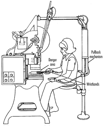
Pullback devices utilize a series of cables attached to the operator’s hands, wrists and/or arms and are primarily used on machines with stroking action. When the slide/ram is up, the operator is allowed access to the point of operation. When the slide/ram begins to descend, a mechanical linkage automatically assures withdrawal of the hands from the point of operation. Figure 21 shows a pullback device on a small press.
Figure 21. Pullback device on power press
Restraint devices
Restraint devices, which utilize cables or straps that are attached between a fixed point and the operator’s hands, have been used in some countries. These devices are not generally considered to be acceptable safeguards because they are easily bypassed by the operator, thus allowing hands to be placed into the danger zone. (See table 2.)
Table 2. Devices
|
Method |
Safeguarding action |
Advantages |
Limitations |
|
Photoelectric |
· Machine will not start cycling when the light field is interrupted |
· Can allow freer movement for operator |
· Does not protect against mechanical failure |
|
Radio frequency |
· Machine cycling will not start when the capacitance field is interrupted |
· Can allow freer movement for operator |
· Does not protect against mechanical failure |
|
Electro-mechanical |
· Contact bar or probe travels a predetermined distance between the operator and the danger area |
· Can allow access at the point of operation |
· Contact bar or probe must be properly adjusted for each application; this adjustment must be maintained properly |
|
Pullback |
· As the machine begins to cycle, the operator’s hands are pulled out of the danger area |
· Eliminates the need for auxiliary barriers or other interference at the danger area |
· Limits movement of operator |
|
Safety trip controls: |
· Stops machine when tripped |
· Simplicity of use |
· All controls must be manually activated |
|
Two-hand control |
· Concurrent use of both hands is required, preventing the operator from entering the danger area |
· Operator’s hands are at a predetermined location away from danger area |
· Requires a partial cycle machine with a brake |
|
Two-hand trip |
· Concurrent use of two hands on separate controls prevent hands from being in danger area when machine cycle starts |
· Operator’s hands are away from danger area |
· Operator may try to reach into danger area after tripping machine |
|
Gate |
· Provides a barrier between danger area and operator or other personnel |
· Can prevent reaching into or walking into the danger area |
· May require frequent inspection and regular maintenance |
Safety control devices
All of these safety control devices are activated manually and must be manually reset to restart the machine:
- Safety trip controls such as pressure bars, trip rods and tripwires are manual controls which provide a quick means for deactivating the machine in an emergency situation.
- Pressure-sensitive body bars, when depressed, will deactivate the machine if the operator or anyone trips, loses balance or is drawn toward the machine. The positioning of the bar is critical, as it must stop the machine before a part of the body reaches the danger area. Figure 22 shows a pressure-sensitive body bar located on the front of a rubber mill.
Figure 22. Pressure-sensitive body bar on rubber mill

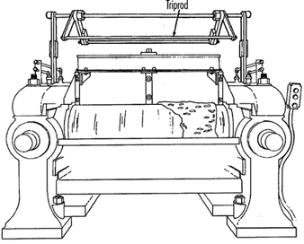
- Safety trip-rod devices deactivate the machine when pressed by hand. Because they have to be actuated by the operator during an emergency situation, their proper position is critical. Figure 23 shows a trip-rod located above the rubber mill.
Figure 23. Safety trip-rod on rubber mill
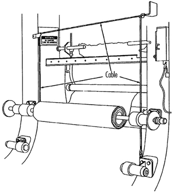
- Safety tripwire cables are located around the perimeter of, or near the danger area. The operator must be able to reach the cable with either hand to stop the machine. Figure 24 shows a calender equipped with this type of control.
Figure 24. Safety tripwire cable on calender
- Two-hand controls require constant, concurrent pressure for the operator to activate the machine. When installed on power presses, these controls use a part-revolution clutch and a brake monitor, as shown in figure 25. With this type of device, the operator’s hands are required to be at a safe location (on control buttons) and at a safe distance from the danger area while the machine completes its closing cycle.
Figure 25. Two-hand control buttons on part-revolution clutch power press

- Two-hand trip. The two-hand trip shown in figure 26 is usually used with machines equipped with full-revolution clutches. It requires concurrent application of both of the operator’s control buttons to activate the machine cycle, after which the hands are free. The trips must be placed far enough from the point of operation to make it impossible for operators to move their hands from the trip buttons or handles into the point of operation before the first half of the cycle is completed. The operator’s hands are kept far enough away to prevent them from being accidentally placed in the danger area before the slide/ram or blade reaches the full down position.
Figure 26. Two-hand control buttons on full-revolution clutch power press
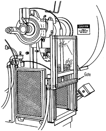
- Gates are safety control devices which provide a movable barrier that protects the operator at the point of operation before the machine cycle can be started. Gates are often designed to be operated with each machine cycle. Figure 27 shows a gate on a power press. If the gate is not permitted to descend to the fully closed position, the press will not function. Another application of gates is their use as a component of a perimeter safeguarding system, where the gates provide protection to the operators and to pedestrian traffic.
Figure 27. Power press with gate
Safeguarding by location or distance
To safeguard a machine by location, the machine or its dangerous moving parts must be so positioned that hazardous areas are not accessible or do not present a hazard to a worker during the normal operation of the machine. This may be accomplished with enclosure walls or fences that restrict access to machines, or by locating a machine so that a plant design feature, such as a wall, protects the worker and other personnel. Another possibility is to have dangerous parts located high enough to be out of the normal reach of any worker. A thorough hazard analysis of each machine and particular situation is essential before attempting this safeguarding technique. The examples mentioned below are a few of the numerous applications of the principle of safeguarding by location/distance.
Feeding process. The feeding process can be safeguarded by location if a safe distance can be maintained to protect the worker’s hands. The dimensions of the stock being worked on may provide adequate safety. For example, when operating a single-end punching machine, if the stock is several feet long and only one end of the stock is being worked on, the operator may be able to hold the opposite end while the work is being performed. However, depending upon the machine, protection might still be required for other personnel.
Positioning controls. The positioning of the operator’s control station provides a potential approach to safeguarding by location. Operator controls may be located at a safe distance from the machine if there is no reason for the operator to be in attendance at the machine.
Feeding and ejection safeguarding methods
Many feeding and ejection methods do not require the operators to place their hands in the danger area. In some cases, no operator involvement is necessary after the machine is set up, whereas in other situations, operators can manually feed the stock with the assistance of a feeding mechanism. Furthermore, ejection methods may be designed which do not require any operator involvement after the machine starts to function. Some feeding and ejection methods may even create hazards themselves, such as a robot which may eliminate the need for an operator to be near the machine but may create a new hazard by the movement of its arm. (See table 3.)
Table 3. Feeding and ejection methods
|
Method |
Safeguarding action |
Advantages |
Limitations |
|
Automatic feed |
· Stock is fed from rolls, indexed by machine mechanism, etc. |
· Eliminates the need for operator involvement in the danger area |
· Other guards are also required for operator protection—usually fixed barrier guards |
|
Semi-automatic |
· Stock is fed by chutes, movable dies, dial |
· Eliminates the need for operator involvement in the danger area |
· Other guards are also required for operator protection—usually fixed barrier guards |
|
Automatic |
· Work pieces are ejected by air or mechanical means |
· Eliminates the need for operator involvement in the danger area |
· May create a hazard of blowing chips or debris |
|
Semi-automatic |
· Work pieces are ejected by mechanical |
· Operater does not have to enter danger area to remove finished work |
· Other guards are required for operator |
|
Robots |
· They perform work usually done by operator |
· Operator does not have to enter danger area |
· Can create hazards themselves |
Using one of the following five feeding and ejection methods to safeguard machines does not eliminate the need for guards and other devices, which must be used as necessary to provide protection from exposure to hazards.
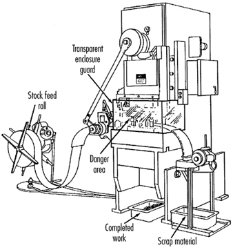
Automatic feed. Automatic feeds reduce the operator exposure during the work process, and often do not require any effort by the operator after the machine is set up and running. The power press in figure 28 has an automatic feeding mechanism with a transparent fixed enclosure guard at the danger area.
Figure 28. Power press with automatic feed
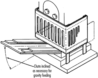
Semi-automatic feed. With semi-automatic feeding, as in the case of a power press, the operator uses a mechanism to place the piece being processed under the ram at each stroke. The operator does not need to reach into the danger area, and the danger area is completely enclosed. Figure 29 shows a chute feed into which each piece is placed by hand. Using a chute feed on an inclined press not only helps centre the piece as it slides into the die, but may also simplify the problem of ejection.
Figure 29. Power press with chute feed
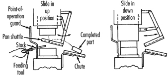
Automatic ejection. Automatic ejection may employ either air pressure or a mechanical apparatus to remove the completed part from a press, and may be interlocked with the operating controls to prevent operation until part ejection is completed. The pan shuttle mechanism shown in figure 30 moves under the finished part as the slide moves toward the up position. The shuttle then catches the part stripped from the slide by the knockout pins and deflects it into a chute. When the ram moves down toward the next blank, the pan shuttle moves away from the die area.
Figure 30. Shuttle ejection system
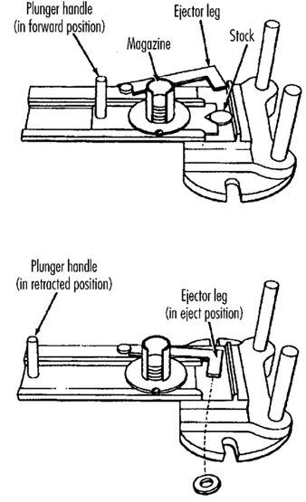
Semi-automatic ejection. Figure 31 shows a semi-automatic ejection mechanism used on a power press. When the plunger is withdrawn from the die area, the ejector leg, which is mechanically coupled to the plunger, kicks the completed work out.
Figure 31. Semi-automatic ejection mechanism
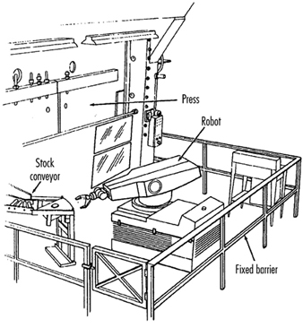
Robots. Robots are complex devices that load and unload stock, assemble parts, transfer objects or perform work otherwise done by an operator, thereby eliminating operator exposure to hazards. They are best used in high-production processes requiring repeated routines, where they can guard against other hazards to employees. Robots may create hazards, and appropriate guards must be used. Figure 32 shows an example of a robot feeding a press.
Figure 32. Using barrier guards to protect robot envelope
Miscellaneous safeguarding aids
Although miscellaneous safeguarding aids do not give complete protection from machine hazards, they may provide operators with an extra margin of safety. Sound judgement is needed in their application and use.
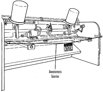
Awareness barriers. Awareness barriers do not provide physical protection, but serve only to remind operators that they are approaching the danger area. Generally, awareness barriers are not considered adequate when continual exposure to the hazard exists. Figure 33 shows a rope used as an awareness barrier on the rear of a power squaring shear. Barriers do not physically prevent persons from entering danger areas, but only provide awareness of the hazard.
Figure 33. Rear view of power shearing square
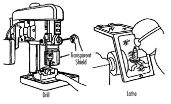
Shields. Shields may be used to provide protection from flying particles, splashing metal-working fluids or coolants. Figure 34 shows two potential applications.
Figure 34. Applications of shields
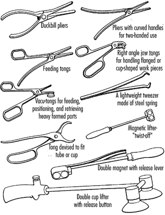
Holding tools. Holding tools place and remove stock. A typical use would be for reaching into the danger area of a press or press brake. Figure 35 shows an assortment of tools for this purpose. Holding tools should not be used instead of other machine safeguards; they are merely a supplement to the protection that other guards provide.
Figure 35. Holding tools
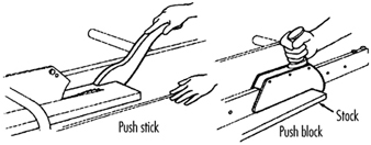
Push sticks or blocks, such as shown in figure 36, may be used when feeding stock into a machine, such as a saw blade. When it becomes necessary for hands to be in close proximity to the blade, the push stick or block may provide a margin of safety and prevent injury.
Figure 36. Use of push stick or push block