- You are here:
-
Home

-
Part X. Industries Based on Biological Resources
-
Paper and Pulp Industry
- Major Sectors and Processes
Chlorine and Caustic Production
The Chlorine Institute, Inc.
Electrolysis of salt brines produces chlorine and caustic. Sodium chloride (NaCl) is the primary salt used; it yields caustic soda (NaOH). However, the use of potassium chloride (KCl) produces caustic potash (KOH).
2 NaCl + 2 H2O → Cl2↑+ 2 NaOH + H2↑
salt + water → chlorine (gas) + caustic + hydrogen (gas)
Currently the diaphragm cell process is in greatest use for the commercial production of chlorine followed by the mercury cell process and then the membrane cell process. Due to economic, environmental and product quality issues, manufacturers now prefer the membrane cell process for new production facilities.
The Diaphragm Cell Process
A diaphragm cell (see figure 1) is fed saturated salt brine into a compartment containing a titanium anode coated with salts of ruthenium and other metals. A plastic cell head collects the hot, wet chlorine gas produced at this anode. Suction by a compressor then draws the chlorine into a collection header for further processing consisting of cooling, drying and compression. Water and unreacted brine percolate through a porous diaphragm separator into the cathode compartment where water reacts at a steel cathode to produce sodium hydroxide (caustic soda) and hydrogen. The diaphragm keeps the chlorine produced at the anode from the sodium hydroxide and hydrogen produced at the cathode. If these products combine, the result is sodium hypochlorite (bleach) or sodium chlorate. Commercial producers of sodium chlorate use cells that do not have separators. The most common diaphragm is a composite of asbestos and a fluorocarbon polymer. Modern diaphragm cell plants do not have the health or environmental problems historically associated with the use of asbestos diaphragms. Some plants do employ non-asbestos diaphragms, which are now commercially available. The diaphragm cell process produces a weak sodium hydroxide solution containing unreacted salt. An additional evaporation process concentrates the caustic and removes most of the salt to make a caustic of commercial quality.
Figure 1. Types of chloralkali cell processes
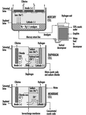
The Mercury Cell Process
A mercury cell actually consists of two electrochemical cells. The reaction in the first cell at the anode is:
2 Cl– → C12 + 2 e–
chloride → chlorine + electrons
The reaction in the first cell at the cathode is:
Na+ + Hg + e– → Na · Hg
sodium ion + mercury + electrons → sodium amalgam
Salt brine flows in an inclined steel trough with rubber-lined sides (see figure 4) Mercury, the cathode, flows under the brine. Anodes of coated titanium are suspended in the brine for the production of chlorine, which exits the cell to a collection and processing system. Sodium is electrolyzed in the cell and leaves the first cell amalgamated with the mercury. This amalgam flows into a second electrochemical cell called the decomposer. The decomposer is a cell with graphite as a cathode and the amalgam as the anode.
The reaction in the decomposer is:
2 Na•Hg + 2 H2O → 2 NaOH + 2 Hg + H2 ↑
The mercury cell process produces commercial (50%) NaOH directly from the cell.
The Membrane Cell Process
The electrochemical reactions in a membrane cell are the same as in the diaphragm cell. A cation-exchange membrane is used in place of the porous diaphragm (see figure 1). This membrane prevents the migration of chloride ions into the catholyte, thereby producing essentially salt free 30 to 35% caustic directly from the cell. The elimination of the need to remove salt makes the evaporation of the caustic to commercial 50% strength simpler, and it requires less investment and energy. Expensive nickel is used as the cathode in the membrane cell due to the stronger caustic.
Safety and Health Hazards
At ordinary temperatures, dry chlorine, either liquid or gas, does not corrode steel. Wet chlorine is highly corrosive because it forms hydrochloric and hypochlorous acids. Precautions should be taken to keep chlorine and chlorine equipment dry. Piping, valves and containers should be closed or capped when not in use to keep out atmospheric moisture. If water is used on a chlorine leak the resulting corrosive conditions will make the leak worse.
The volume of liquid chlorine increases with temperature. Precautions should be taken to avoid hydrostatic rupture of piping, vessels, containers or other equipment filled with liquid chlorine.
Hydrogen is a co-product of all chlorine manufactured by the electrolysis of aqueous brine solutions. Within a known concentration range, mixtures of chlorine and hydrogen are flammable and potentially explosive. The reaction of chlorine and hydrogen can be initiated by direct sunlight, other sources of ultraviolet light, static electricity or sharp impact.
Small quantities of nitrogen trichloride, an unstable and highly explosive compound, can be produced in the manufacturing of chlorine. When liquid chlorine containing nitrogen trichloride is evaporated, the nitrogen trichloride may reach hazardous concentrations in the remaining liquid chlorine.
Chlorine can react, at times explosively, with a number of organic materials such as oil and grease from sources such as air compressors, valves, pumps and oil-diaphragm instrumentation, as well as wood and rags from maintenance work.
As soon as there is any indication of a chlorine release, immediate steps must be taken to correct the condition. Chlorine leaks always get worse if they are not promptly corrected. When a chlorine leak occurs, authorized, trained personnel equipped with respiratory and other appropriate personal protective equipment (PPE) should investigate and take proper action. Personnel should not enter into atmospheres containing concentrations of chlorine in excess of the immediately dangerous to life and health (IDLH) concentration (10 ppm) without appropriate PPE and back-up personnel. Unnecessary personnel should be kept away and the hazard area should be isolated. Persons potentially affected by a chlorine release should be evacuated or sheltered in place as circumstances warrant.
Area chlorine monitors and wind direction indicators can supply timely information (e.g., escape routes) to help determine whether personnel are to be evacuated or sheltered in place.
When evacuation is utilized, potentially exposed persons should move to a point upwind of the leak. Because chlorine is heavier than air, higher elevations are preferable. To escape in the shortest time, persons already in a contaminated area should move crosswind.
When inside a building and sheltering in place is selected, shelter can be achieved by closing all windows, doors and other openings, and turning off air conditioners and air intake systems. Personnel should move to the side of the building furthest from the release.
Care must be taken not to position personnel without an escape route. A safe position may be made hazardous by a change in wind direction. New leaks may occur or the existing leak may get larger.
If fire is present or imminent, chlorine containers and equipment should be moved away from the fire, if possible. If a non-leaking container or equipment cannot be moved, it should be kept cool by applying water. Water should not be used directly on a chlorine leak. Chlorine and water react forming acids and the leak quickly will get worse. However, where several containers are involved and some are leaking, it may be prudent to use a water spray to help prevent overpressure of the non-leaking containers.
Whenever containers have been exposed to flames, cooling water should be applied until well after the fire is out and the containers are cooled. Containers exposed to fire should be isolated and the supplier should be contacted as soon as possible.
Sodium hydroxide solutions are corrosive, especially when concentrated. Workers at risk for exposure to spills and leaks should wear gloves, face shield and goggles and other protective clothing.
Acknowledgements: Dr. R.G. Smerko is acknowledged for making available the resources of the Chlorine Institute, Inc.
Major Unit Operations and Processes: An Overview
This article presents information on basic process equipment, storage, plant layout and operations considerations in chemical process industries, including major items and concepts that are broadly applicable throughout the chemical industry. However, much of the equipment required in chemical processing is highly specialized and cannot be broadly generalized. More detailed information on toxicity and hazardous materials and process safety are reviewed elsewhere in this Encyclopaedia.
There are two basic categories of layout in chemical processing industries: plant layout, which covers all process units, utilities, storage areas, loading/unloading areas, buildings, shops and warehousing, and unit or process layout, which covers only equipment placement for a specific process, also termed a process block.
Plant Layout
Siting
Locating or siting an overall plant is based upon a number of general factors, as shown in table 1 (CCPS 1993). These factors vary considerably with locations, governments and economic policies. Of these various factors, safety considerations are an extremely important concern, and in some locations they can be the major factor that governs plant siting.
Table 1. Some general site selection factors
- Population density around the site
- Natural disaster occurrence (earthquake, flood, etc.)
- Prevailing winds and meteorological data
- Availability of power, steam and water
- Safety considerations
- Air, water and waste regulations and their complexity
- Accessibility to raw materials and markets
- Transportation
- Siting permits and complexity of obtaining them
- Interaction requirements in industrial developments
- Labour availability and costs
- Investment incentives
One important aspect of plant safety in siting is defining a buffer zone between a plant with hazardous processes and nearby plants, dwellings, schools, hospitals, highways, waterways and airplane corridors. Some overall safety considerations are presented in table 2. The buffer zone is important because distance tends to reduce or mitigate potential exposures from various accidents. The distance necessary to reduce toxic concentrations to acceptable levels through atmospheric interaction and the dispersion of toxic materials from an accidental release can be defined. Moreover, the time lag between a toxic release and public exposure created by a buffer zone can be used to warn the population through pre-planned emergency response programmes. Since plants have various types of facilities containing toxic materials, dispersion analyses should be conducted on the potentially hazardous systems to ensure the buffer zone is adequate in each area surrounding the plant perimeter.
Table 2. Plant siting safety considerations
- Buffer zone
- Location of other hazardous installations in vicinity
- Inventory of toxic and hazardous materials
- Adequacy of firefighting water supply
- Emergency equipment access
- Availability of emergency response support from adjacent industries and the community
- Weather extremes and prevailing winds
- Location of highways, waterways, railroad and airplane corridors
- Environmental and waste disposal restrictions during emergencies
- Draining and grade slope
- Maintenance and inspection
Fire is a potential hazard in process plants and facilities. Large fires can be a source of thermal radiation which can also be mitigated by distance. Elevated flares can also be a source of thermal radiation during an emergency or startup/shutdown operation. A flare is a device that automatically burns exhaust gases or emergency vapour releases at elevated positions or special ground locations. These should be sited away from the plant perimeter (for community protection) and an area at the flare base should be prohibited to workers. If not operated properly, liquid carryover into the flare can result in burning liquid droplets. In addition to fire, there can be explosions within equipment or a vapour cloud that produces blast waves. Although distance will reduce the blast intensity somewhat over the buffer zone, the blast will still have an effect on the nearby community.
The potential of accidental releases or fires from existing facilities that may be near the proposed site should also be considered. Potential incidents should be modelled and evaluated to determine the possible effect on the proposed plant layout. Emergency responses to an external event should be evaluated and responses coordinated with other plants and affected communities.
Other considerations
Dow Chemical Company has developed another approach to plant layout based on an acceptable level of Maximum Probable Property Damage (MPPD) and Business Interruption Risk (B1) (Dow Chemical Company 1994a). These considerations are important for both new and existing plants. The Dow Fire and Explosion Index is useful in new plant layouts or in the addition of equipment to existing plants. If risks calculated from the Index are found to be unacceptable, the separation distances should be increased. Alternatively, layout changes may also reduce the risk potential.
Overall layout
In an overall plant layout, the prevailing winds are an important consideration. Ignition sources should be located upwind of potential leak sources. Fired heaters, boilers, incinerators and flares are in this category (CCPS 1993). The location of storage tanks downwind of process units and utilities is another recommendation (CCPS 1993). Environmental regulations have led to significantly reduced leakage from tankage (Lipton and Lynch 1994).
Minimum separation distances have been outlined in various publications for process units, equipment and different plant functions (CCPS 1993; Dow Chemical Company 1994a; IRI 1991). General facilities that normally have recommended distance separations in overall plant layouts are shown in table 3. Actual distance recommendations should be carefully defined. While fired heaters and process furnaces are not shown in table 3, they are an important item and recommended distance separations must be included in a unit process layout.
Table 3. Facilities generally separated in overall plant layouts
- Process units
- Tank farms
- Loading and unloading facilities
- Flares
- Power, boilers and incinerators
- Cooling towers
- Substations, large electrical switch yards
- Central control houses
- Warehouses
- Analytical laboratories
- Incoming utility metering and block systems
- Fire hoses, fixed monitors, reservoirs and emergency fire pumps
- Waste treatment areas
- Maintenance buildings and areas
- Administrative buildings
In addition, roads are necessary for emergency and maintenance vehicle or equipment access and require careful placement between process units and throughout the various sections of the plant. Acceptable clearances for overhead pipe racks and other overhead equipment should be established along with lateral clearances at cross-roads and entrances to all facilities.
The layout requirements can be based on recommended minimum separation distances (CCPS 1993; NFPA 1990; IRI 1991; Mecklenburgh 1985) or determined through a hazard analysis (Dow Chemical Company 1994a).
Process Unit Layout
Table 3 presents an overall plant separations layout summary. The process units are contained within the specific block shown in the general layout. The chemical process is generally shown in detail in process and implementation diagrams (P&IDs). A process layout requires considerations beyond specific equipment separation distances, some of which are shown in table 4.
Table 4. General considerations in a process unit layout
- Area definition for future expansion and unit accessibility
- Repair equipment accessibility for frequent maintenance
- Space requirements for individual equipment repair (e.g., area needed for pulling heat exchanger bundle or accessibility for control valve)
- Barriers for high pressure equipment or reactors with explosion potential
- Mechanical and space requirements for loading/unloading solids-filled reactors or towers
- Space for venting dust explosions
- Separation of frequently opened or maintained equipment from high temperature piping, vessels, etc.
- Special buildings or structures and necessary clearance (e.g., a compressor house with an internal bridge crane or external crane)
The assemblage of equipment in any particular process unit will vary considerably, depending on the process. The toxicity and hazardous characteristics of the streams and materials within the units also vary widely. Despite these differences, minimum distance standards have been developed for many equipment items (CCPS 1993; NFPA 1990; IRI 1991; Mecklenburgh 1985). Procedures for calculating potential leakage and toxic exposures from process equipment that can also affect separation distance are available (Dow Chemical Company 1994b). In addition, dispersion analysis can be applied when leakage estimates have been calculated.
Equipment and separation distance
A matrix technique can be used to calculate the space needed for separating equipment (CCPS 1993; IRI 1991). Calculations based upon specific processing conditions and an equipment hazard evaluation may result in separation distances that differ from a standard matrix guide.
Extensive lists for a matrix can be developed by refinement of individual categories and by the addition of equipment. For example, compressors may be split into several types, such as those handling inert gas, air and hazardous gases. Separation distances for engine-driven compressors may differ from motor- or steam-driven machines. Separation distances in storage facilities that house liquefied gases should be analysed on the basis of whether the gas is inert.
The process battery limits should be carefully defined. They are the boundary lines or plot limits for a process unit (the name derives from the early use of a battery of ovens in processing). Other units, roads, utilities, pipeways, runoff ditches and so on are plotted based upon battery limits. While unit equipment location does not extend to the battery limits, separation distances of equipment from battery limits should be defined.
Control rooms or control houses
In the past each process unit was designed with a control room that provided operational control of the process. With the advent of electronic instrumentation and computer-controlled processing, individual control rooms have been replaced by a central control room that controls a number of process units in many operations. The centralized control room is economically advantageous because of process optimization and increases in efficiency of personnel. Individual process units still exist and, in some specialized units, older control houses which have been supplanted by centralized control rooms may still be used for local process monitoring and for emergency control. Although control room functions and locations are generally determined by process economics, the design of the control room or control house is very important for maintaining emergency control and for worker protection. Some considerations for both central and local control houses include:
- pressurizing the control house to prevent the entrance of toxic and hazardous vapours
- designing the control house for blast and explosion resistance
- establishing a location that is at minimal risk (based upon separation distance and probability of gas releases)
- purifying all inlet air and installing an inlet stack location that minimizes the intake of toxic or hazardous vapours
- sealing all sewer outlets from the control house
- installing a fire suppression system.
Inventory reduction
An important consideration in process and plant layouts is the quantity of toxic and hazardous material in the overall inventory, including the equipment. The consequences of a leak are more severe as the volume of material increases. Consequently, the inventory should be minimized wherever possible. Improved processing that reduces the number and size of pieces of equipment reduces the inventory, lowers the risk and also results in lower investment and improved operating efficiencies.
Some potential inventory reduction considerations are shown in table 6. Where a new process facility will be installed, processing should be optimized by taking into consideration some of the objectives shown in table 5.
Table 5. Steps for limiting inventory
- Reducing storage tank inventory reduction through improved process control, operation and just-in-time inventory control
- Eliminating or minimizing onsite tank inventory through process integration
- Using reaction variable analysis and development for reactor volume reduction
- Replacing batch reactors with continuous reactors, which also reduces downstream holdup
- Lowering distillation column holdup through bottoms-volume reductions and tray holdup with either more advanced trays or packings
- Replacing kettle reboilers with thermosyphon reboilers
- Minimizing overhead drum and bottoms surge drum volumes
- Improving pipe layout and sizing to minimize holdup
- Where toxic materials are produced, minimizing the toxic section holdup
Storage Facilities
The storage facilities in a chemical processing plant can house liquid and solid feed, intermediate chemicals, by-products and process products. Products stored in many facilities serve as intermediates or precursors for other processes. Storage may also be required for diluents, solvents or other process materials. All of these materials are generally stored in above-ground storage tankage (AST). Underground tankage is still used in some locations, but use is generally limited due to access problems and limited capacity. In addition, potential leakage of such underground storage tanks (USTs) presents environmental problems when leaks contaminate ground water. General earth contamination can lead to potential atmospheric exposures with higher vapour-pressure materials leaks. Leaked materials can be a potential exposure problem during ground remediation efforts. UST leakage has resulted in stringent environmental regulations in many countries, such as the requirements for double-walled tanks and underground monitoring.
Typical above-ground storage tanks are shown in figure 1. Vertical ASTs are cone or domed roof tanks, floating roof tanks that are covered or non-covered floating roof or external floating roof tanks (EFRTs). Converted or closed roof tanks are EFRTs with covers installed on the tanks that are frequently geodesic type domes. Since EFRTs over time do not maintain a perfectly circular shape, sealing the floating roof is difficult and a covering is installed on the tank. A geodesic dome design eliminates roof trusses needed for cone roof tanks (FRTs). The geodesic dome is more economical than a cone roof and, in addition, the dome reduces losses of materials to the environment.
Figure 1. Typical above-ground storage tanks
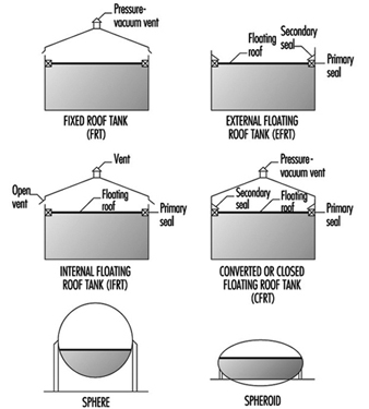
Normally, the tanks are limited to liquid storage where the liquid vapour pressure does not exceed 77 kPa. Where the pressure exceeds this value, spheroids or spheres are used since both are designed for pressure operation. Spheroids can be quite large but are not installed where the pressure may exceed certain limits defined by the mechanical design. For most higher vapour-pressure storage applications, spheres are normally the storage container and are equipped with pressure relief valves to prevent over pressuring. A safety concern that has developed with spheres is rollover, which generates excessive vapour and results in relief valve discharges or in more extreme situations such as sphere wall rupture (CCPS 1993). In general, the liquid contents stratify and if warm (less dense) material is loaded into the sphere bottom, the warm material rises to the surface with the cooler, higher density surface material rolled over to the bottom. The warm surface material vaporizes, raising the pressure, which may result in relief valve discharge or sphere overpressuring.
Tank layout
Tankage layout requires careful planning. There are recommendations for tank separation distances and other considerations (CCPS 1988; 1993). In many locations, separation distances are not specified by code, but minimum distances (OSHA 1994) can be a result of various decisions applicable to separation distances and locations. Some of these considerations are presented in table 6. In addition, tank service is a factor in tank separation for pressurized, refrigerated and atmospheric tanks (CCPS 1993).
Table 6. Tank separation and location considerations
- Separation based on shell to shell distances can be based on references and subject to calculating the thermal radiation distance in the event of fire in an adjacent tank.
- Tanks should be separated from process units.
- A tank location, preferably downwind from other areas, minimizes ignition problems in the event of a tank releasing a significant vapour quantity.
- Storage tanks should have dykes, which are also required by law in most regions.
- Tanks can be grouped for utilization of common dykes and firefighting equipment.
- Dykes should have isolation capability in an emergency.
Dykes are required and are nominally sized volumetrically to hold the contents of a tank. Where multiple tanks are within a dyke, the minimum volumetric dyke capacity is equivalent to the capacity of the largest tank (OSHA 1994). The dyke walls can be constructed of earth, steel, concrete or solid masonry. However, the earth dykes should be impenetrable and have a flat top with a minimum width of 0.61 m. In addition, the soil within the dyked area should also have an impenetrable layer to prevent any chemical or oil leakage into the soil.
Tank leakage
A problem that has been developing through the years is tank leakage as a result of corrosion in the tank bottom. Frequently, tanks have water layers in the tank bottom that can contribute to corrosion, and electrolytic corrosion may occur due to contact with the earth. As a result, regulatory requirements have been instituted in various regions to control tank bottom leakage and underground soil and water contamination from contaminants in the water. A variety of design procedures have been developed to control and monitor leakage (Hagen and Rials 1994). In addition, double bottoms have also been installed. In some installations, cathodic protection has been installed to further control metal deterioration (Barletta, Bayle and Kennelley 1995).
Water draw off
Manually discharging water periodically from the tank bottom can result in exposure. Visual observation to determine the interface through open manual draining can result in worker exposure. A closed discharge can be installed with an interface sensor and control valve minimizing potential worker exposures (Lipton and Lynch 1994). A variety of sensors are commercially available for this service.
Overfilling tanks
Frequently, tanks are overfilled, creating potential safety and worker exposure hazards. This can be prevented with redundant or dual-level instruments controlling inlet block valves or feed pumps (Bahner 1996). For many years, overflow lines were installed on chemical tanks, but they terminated a short distance above a drain opening to permit visual observation of the overflow discharge. Moreover, the drain had to be sized for greater than the maximum fill rate to ensure proper drainage. However, such a system is a potential exposure source. This can be eliminated by connecting the overflow line directly to the drain with a flow indicator in the line to show the overflow. Although this will function satisfactorily, this results in overloading the drain system with a very large contaminant volume and potential health and safety problems.
Tank inspection and cleaning
Periodically, tanks are removed from service for inspection and/ or cleaning. These procedures must be carefully controlled to prevent worker exposure and minimize potential safety hazards. Following draining, tanks are frequently flushed with water to remove process liquid traces. Historically, the tanks have then been cleaned manually or mechanically where necessary. When tanks are drained, they are filled with vapour that may be toxic and can be within a combustible range. Water flushing may not significantly affect vapour toxicity, but it may reduce potential combustion problems. With floating roofs, the material below the floating roof can be flushed and drained, but some tanks may still have material in the sump. This bottom material must be removed manually and may present potential exposure concerns. Personnel may be required to wear personal protective equipment (PPE).
Normally, enclosed tanks and any volume below the floating roofs are purged with air until a specified oxygen concentration level is achieved before entry is permitted. However, concentration measurements should be continually obtained to ensure toxic concentration levels are satisfactory and do not change.
Vapour venting and emission control
For fixed roof or converted floating roof tanks (CFRTs), venting to the atmosphere may not be acceptable in many locations. The pressure-vacuum (PV) vent (shown in figure 2 these tanks are removed and the vapours flow through a closed duct to a control device where the contaminants are destroyed or recovered. For both tanks, an inert purge (e.g., nitrogen) can be injected to eliminate the diurnal vacuum effect and maintain a positive pressure for the recovery device. In the CFRT tank, the nitrogen eliminates the diurnal effect and reduces any vapours to the atmosphere through a PV vent. However, vapour emissions are not eliminated. A large number of control devices and techniques are available including combustion, absorbers, condensers and absorption (Moretti and Mukhopadhyay 1993; Carroll and Ruddy 1993; Basta 1994; Pennington 1996; Siegall 1996). Selection of a control system is a function of final emission targets and operating and investment costs.
In floating roof tanks, both external and internal, seals and auxiliary fitting controls effectively minimize vapour losses.
Safety hazards
Flammability is a major concern in tankage and fire-fighting systems are required to aid in control and prevention of expanded fire zones. Firewater systems and installation recommendations are available (CCPS 1993; Dow Chemical Company 1994a; NFPA 1990). Water can be sprayed directly on a fire under certain conditions and is essential in cooling adjacent tankage or equipment to prevent overheating. In addition, foam is an effective fire-fighting agent and permanent foam equipment can be installed on tanks. The installation of foam equipment on mobile fire-fighting equipment should be reviewed with a manufacturer. Environmentally acceptable and low toxicity foams are now available that are effective and comparable to other foams in quickly extinguishing fires.
Processing Equipment
A wide variety of process equipment is required in chemicals processing as a result of the numerous processes, specialized process requirements and variations in products. Consequently, all of the chemical equipment in use today cannot be reviewed; this section will concentrate on the more widely applied equipment found in processing sequences.
Reactors
There are a large number of reactor types in the chemical industry. The basis for reactor selection is a function of a number of variables, beginning with classifying whether the reaction is a batch or continuous reaction. Frequently, batch reactions are converted to continuous operations as experience with the reaction increases and some modifications, such as improved catalysts, become available. Continuous reaction processing is generally more efficient and produces a more consistent product, which is desirable in meeting product quality targets. However, there are still a large number of batch operations.
Reaction
In all reactions, the classifications of a reaction as exothermic or endothermic (producing heat or requiring heat) is necessary in order to define the heating or cooling requirements necessary to control the reaction. In addition, runaway reaction criteria must be established to install instrument sensors and controls that can prevent a reaction from becoming out of control. Prior to full-scale operation of a reactor, emergency procedures must be investigated and developed to ensure the runaway reaction is safely contained. Some of the various potential solutions are emergency control equipment that is automatically activated, injection of a chemical that stops the reaction and vent facilities that can accommodate and contain the reactor contents. Safety valve and vent operation are extremely important requiring well-maintained and functioning equipment at all times. Consequently, multiple interlocked safety valves are frequently installed to ensure that maintenance on one valve will not reduce the required relief capacity.
Should a safety valve or vent discharge due to malfunction, the discharge effluent must be contained in practically all circumstances to minimize potential safety and health hazards. As a result, the method of containing the emergency discharge through piping along with final disposition of the reactor discharge should be carefully analysed. In general, liquid and vapour should be separated with the vapour sent to a flare or recovery and liquid recycled where possible. Solids removal may require some study.
Batch
In reactors involving exothermic reactions, an important consideration is fouling on the walls or internal tubing by the cooling media used to maintain the temperature. Removal of fouled material varies considerably and the method of removal is a function of the fouled material characteristics. Fouled material can be removed with a solvent, a high-pressure jet nozzle stream or, in some cases, manually. In all these procedures, safety and exposure must be carefully controlled. Movement of material in and out of the reactor must not permit the entrance of air, which may result in a flammable vapour mixture. Vacuums should be broken with an inert gas (e.g., nitrogen). Vessel entry for inspection or work can be classified as entry into a confined space and the rules for this procedure should be observed. Vapour and dermal toxicity should be understood and technicians must be knowledgeable about health hazards.
Continuous
Flow-through reactors can be filled with liquid or a vapour and liquid. Some reactions produce slurries in the reactors. Also, there are reactors that contain solid catalysts. The reaction fluid may be liquid, vapour or a combination of vapour and liquid. Solid catalysts, which promote a reaction without participating in it, are normally contained within grids and are termed fixed beds. The fixed-bed reactors may have single or multiple beds and can have exotherinic or endothermic reactions, with most reactions requiring a constant temperature (isothermal) through each bed. This frequently requires the injection of feed streams or a diluent at various locations between beds to control the temperature. With these reaction systems, temperature indication and sensor location through the beds are extremely important to prevent a reaction runaway and product yield or quality changes.
Fixed beds generally lose their activity and must be regenerated or replaced. For regeneration, deposits on the bed may be burned off, dissolved in a solvent or, in some cases, regenerated through the injection of a chemical in an inert fluid into the bed, thereby restoring catalyst activity. Depending on the catalyst, one of these techniques may be applied. Where beds are burned, the reactor is emptied and purged of all process fluids then filled with an inert gas (usually nitrogen), which is heated and recirculated, raising the bed to a specified temperature level. At this point, a very small volume of oxygen is added to the inert stream to initiate a flame front that gradually moves through the bed and controls the temperature rise. Excessive oxygen quantities have a deleterious effect on the catalyst.
Fixed-bed catalyst removal
Removal of fixed-bed catalysts must be carefully controlled. The reactors are drained of process fluid and then the remaining fluid is displaced with a flushing fluid or purged with a vapour until all of the process fluid has been removed. Final purging may require other techniques before the vessel can be purged with an inert gas or air prior to opening the vessel or discharging the catalyst from the vessel under an inert blanket. Should water be used in this process, the water is drained through closed piping to a process sewer. Some catalysts are sensitive to air or oxygen, becoming pyrophoric or toxic. These require special procedures to eliminate air during filling or emptying the vessels. Personal protection along with handling procedures must be carefully defined to minimize potential exposures and protect personnel.
Spent catalyst disposal may require further treating before it is sent to a catalyst manufacturer for recycling or into an environmentally acceptable disposal procedure.
Other catalyst systems
Gas flowing through a loose solid catalyst bed expands the bed and forms a suspension that is similar to a liquid and termed a fluid bed. This type of reaction is used in various processes. Spent catalysts are removed as a gas-solids side stream for regeneration and then returned to the process through an enclosed system. In other reactions, catalyst activity may be very high and, although catalyst is discharged in the product, the concentration is extremely low and does not pose a problem. Where a high concentration of catalyst solids in the product vapour is undesirable, solids carryover must be removed before purification. However, traces of solids will remain. These are removed for disposal in one of the by-product streams, which in turn must be clarified.
In situations where spent catalyst is regenerated through burning, extensive solids recovery facilities are required in fluid-bed systems to meet environmental restrictions. Recovery may consist of various combinations of cyclones, electric precipitators, bag filters) and/ or scrubbers. Where burning occurs in fixed beds, the basic concern is temperature control.
Since fluid-bed catalysts are frequently within the respiratory range, care must be exercised during solids handling to ensure worker protection with either fresh or recovered catalysts.
In some instances a vacuum may be used to remove various components from a fixed bed. In these situations, a steam-driven vacuum jet is frequently the vacuum producer. This produces a steam discharge that frequently contains toxic materials although in very low concentration in the jet stream. However, the discharge of a steam jet should be carefully reviewed to determine contaminant quantities, toxicity and potential dispersion if it is discharged directly to the atmosphere. Should this be unsatisfactory, the jet discharge may require condensing in a sump where all vapours are controlled and the water is sent to the closed sewer system. A rotary vacuum pump will perform in this service. The discharge from a reciprocating vacuum pump may not be permitted to discharge directly to the atmosphere, but can in some instances discharge into a flare line, incinerator or process heater.
Safety
In all reactors, pressure increases are a major concern since the vessel pressure rating must not be exceeded. These pressure increases may be a result of poor process control, malfunction or a runaway reaction. Consequently, pressure relief systems are required to maintain vessel integrity by preventing reactor overpressuring. Relief valve discharges must be carefully designed to maintain adequate relief under all conditions, including relief-valve maintenance. Multiple valves may be required. Should a relief valve be designed to discharge into the atmosphere, the discharge point should be elevated above all nearby structures and a dispersion analysis should be conducted to ensure adequate protection for workers and nearby communities.
If a rupture disk is installed with a safety valve, the discharge should also be enclosed and the final discharge location designated as described above. Since a disk rupture will not reseat, a disk without a safety valve will probably release most of the reactor contents and air may enter the reactor at the end of the release. This requires a careful analysis to ensure that a flammable situation is not created and that highly undesirable reactions do not occur. Moreover, the discharge from a disk may release liquid and the vent system must be designed to contain all liquids with vapour discharged, as described above. Atmospheric emergency releases must be approved by regulatory authorities before installation.
Mixer agitators installed in reactors are sealed. Leaks may be hazardous and if they occur the seal must be repaired which requires a reactor shutdown. The reactor contents may require special handling or precautions and an emergency shutdown procedure should include reaction termination and disposition of the reactor contents. Flammability and exposure control must be carefully reviewed for each step including final disposition of the reactor mix. Since a shutdown can be expensive and involve production loss, magnetic driven mixers and newer seal systems have been introduced to reduce maintenance and reactor shutdowns.
Entrance to all reactors requires compliance with safe confined-space entry procedures.
Fractionation or distillation towers
Distillation is a process whereby chemical substances are separated through methods which take advantage of differences in boiling points. The familiar towers in chemical plants and refineries are distillation towers.
Distillation in various forms is a processing step found in the great majority of chemical processes. Fractionation or distillation can be found in purification, separation, stripping, azeotropic and extractive process steps. These applications now include reactive distillation, where a reaction occurs in a separate section of the distillation tower.
Distillation is conducted with a series of trays in a tower, or it can be conducted in a tower filled with packing. The packings have special configurations that readily permit the passage of vapour and liquid, but provide sufficient surface area for vapour-liquid contact and efficient fractionation.
Operation
Heat is normally supplied to a tower with a reboiler, although the heat content of specific streams may be sufficient to eliminate the reboiler. With reboiler heat, multiple step vapour-liquid separation occurs on the trays and lighter materials ascend through the tower. Vapours from the top tray are fully or partially condensed in the overhead condenser. The condensed liquid is collected in the distillate recovery drum, where part of the liquid is recycled to the tower and the other portion is withdrawn and sent to a specific location. Non-condensed vapours may be recovered elsewhere or sent to a control device which can be a combustor or recovery system.
Pressure
Towers typically operate at pressures higher than atmospheric pressure. However, towers are frequently operated under vacuum to minimize liquid temperatures that may affect product quality or in situations where tower materials become a mechanical and economic concern due to the temperature level that may be difficult to achieve. Also, high temperatures may affect the fluid. In heavy petroleum fractions, very high tower bottoms temperatures frequently result in coking problems.
Vacuums are typically obtained with ejectors or vacuum pumps. In process units, vacuum loadings consist of some light vapour materials, inerts that may have been in the tower feed stream and air from leakage. Normally the vacuum system is installed after a condenser to reduce the organic loading to the vacuum system. The vacuum system is sized based upon the estimated vapour loading, with ejectors handling larger vapour loadings. In certain systems a vacuum machine may be directly connected to a condenser outlet. A typical ejector system operation is a combination of ejectors and direct barometric condensers where the ejector vapours have direct contact with the cooling water. Barometric condensers are very large consumers of water and the steam-water mixture results in high water outlet temperatures that tend to vaporize any organic compound traces in the atmospheric barometric sump, potentially increasing workplace exposures. In addition, a large effluent load is added to the waste-water system.
A large water reduction is achieved along with a substantial reduction in steam consumption in modified vacuum systems. Since the vacuum pump will not handle a large vapour load, a steam ejector is used in the first stage in combination with a surface condenser to reduce the vacuum pump load. In addition, a sump drum is installed for above-ground operation. The simpler system reduces waste-water loading and maintains a closed system that eliminates potential vapour exposures.
Safety
All towers and drums must be protected from overpressure that may result from malfunction, fire (Mowrer 1995) or utility failure. A hazard review is necessary and is required by law in some countries. A general process safety management approach that is applicable to process and plant operation improves safety, minimizes losses and protects worker health (Auger 1995; Murphy 1994; Sutton 1995). Protection is provided by pressure relief valves (PRVs) that discharge to the atmosphere or to a closed system. The PRV is generally mounted at the tower top to relieve the large vapour load, although some installations locate the PRV in other tower locations. The PRV can also be located on the distillate overhead recovery drum as long as valves are not placed between the PRV and the tower top. If block valves are installed in the process lines to the condenser then the PRV must be installed on the tower.
When distillation tower overpressure is relieved, under certain emergency scenarios, the PRV discharge may be exceedingly large. Very high loading in a closed system discharge vent line may be the largest load in the system. Since a PRV discharge can be sudden and the overall relieving time may be quite short (less than 15 minutes), this extremely large vapour load must be carefully analysed (Bewanger and Krecter 1995; Boicourt 1995). Since this short, large peak load is difficult to process in control devices such as absorbers, adsorbers, furnaces and so on, the preferable control device in most situations is a flare for vapour destruction. Normally, a number of PRVs are connected to a flare line header that in turn is connected to a single flare. However, the flare and overall system must be carefully designed to cover a large group of potential contingencies (Boicourt 1995).
Health hazards
For direct relief to the atmosphere, a detailed dispersion analysis of the relief valve discharge vapours should be conducted to ensure that workers are not exposed and that community concentrations are well within allowable concentration guidelines. In controlling dispersion, atmospheric relief valve discharge lines may have to be raised to prevent excessive concentrations on nearby structures. A very tall flare-like stack may be necessary to control dispersion.
Another area of concern is entering a tower for maintenance or mechanical changes during a shutdown. This entails entering a confined space and exposes workers to the associated hazards. The flushing and purging method prior to opening must be carefully conducted to ensure minimal exposures by reducing any toxic concentrations below recommended levels. Before commencing with flushing and purging operations, the tower pressure must be reduced and all piping connections to the tower must be blinded (i.e., flat metal disks must be placed between the tower flanges and the connecting pipe flanges). This step should be carefully managed to ensure minimum exposures. In different processes, the methods of clearing the tower of toxic fluids vary. Frequently, the tower fluid is displaced with a fluid that has very low toxicity characteristics. This displacement fluid is then drained and pumped to a selected location. The remaining liquid film and droplets can be steamed to the atmosphere through a top flange that has a special stand-off blind with an opening between the blind and tower flange. Following steaming, air enters the tower through the special blind opening as the tower cools. A manhole at the tower bottom and one at the tower top are opened permitting the blowing of air through the tower. When the internal tower concentration reaches a predetermined level, the tower can be entered.
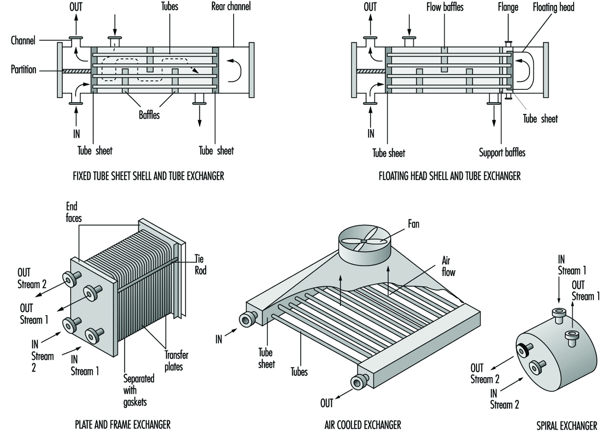
Heat exchangers
There are a wide variety of heat exchangers in the chemical process industry. Heat exchangers are mechanical devices for the transfer of heat to or from a process stream. They are selected in accordance with process conditions and exchanger designs. A few of the common exchanger types are shown in figure 2. Selection of the optimum exchanger for a process service is somewhat complicated and requires a detailed investigation (Woods 1995). In many situations, certain types are not suitable because of pressure, temperature, solids concentration, viscosity, flow quantity and other factors. Moreover, an individual heat exchanger design can vary considerably; several types of floating head tube and sheet exchangers are available (Green, Maloney and Perry 1984). The floating head is normally selected where the temperatures may cause excessive tube expansion that otherwise could not maintain integrity in a fixed tube sheet exchanger. In the simplified floating head exchanger in figure 2, the floating head is contained completely within the exchanger and does not have any connection with the shell cover. In other floating head designs, there may be packing around the floating tubesheet (Green, Maloney and Perry 1984).
Figure 2. Typical heat exchangers
Leakage
The packing on floating tubesheets is in contact with the atmosphere and may be a source of leakage and potential exposure. Other exchangers may also have potential leakage sources and should be examined carefully. As a result of their heat transfer characteristics, plate and frame exchangers are often installed in the chemical industry. The plates have various corrugations and configurations. Plates are separated by gaskets that prevent mixing of the streams and provide an external seal. However, the seals limit temperature applications to about 180 ºC, although seal improvements may overcome this limitation. Since there are a number of plates, the plates must be compressed properly to ensure proper sealing between them. Consequently, careful mechanical installation is necessary to prevent leakage and potential hazards. Since there are a large number of seals, careful seal monitoring is important to minimize potential exposures.
Air cooled exchangers are attractive economically and have been installed in a wide number of process applications and in various locations within process units. To save space, these exchangers are often installed over pipe runs and are frequently stacked. Since tube material selection is important, a variety of materials is used in the chemical industry. These tubes are connected to the tube sheet. This requires use of compatible materials. Leakage through a tube crack or at the tube sheet is a concern since the fan will circulate vapours from the leak and dispersion may result in potential exposures. Air dilution may significantly reduce the potential exposure hazard. However, fans are frequently shut down under some weather conditions and in these circumstances leak concentrations can increase thereby increasing potential exposures. Moreover, if leaking tubes are not repaired, the crack may worsen. With toxic liquids that do not readily vaporize, dripping can occur and result in potential dermal exposure.
Shell and tube heat exchangers may develop leaks through any of the various flanges (Green, Maloney and Perry 1984). Since shell and tube heat exchangers vary in size from small to very large surface areas, the diameter of outer flanges is generally much larger than typical pipe flanges. With these large flanges, the gaskets must not only withstand process conditions, but provide a seal under bolt load variations. Various gasket designs are used. Maintaining constant bolt load stresses on all of the flange bolts is difficult, resulting in leakage in many exchangers. The flange leakage can be controlled with flange sealing rings (Lipton and Lynch 1994).
Tube leakage may occur in any of the available exchanger types, with the exception of plate exchangers and a few other specialty exchangers. However, these latter exchangers have other potential problems. Where tubes leak into a cooling water system, the cooling water discharges the contaminant into a cooling tower which can be an exposure source to both workers and a nearby community. Consequently, the cooling water should be monitored.
The dispersion of cooling tower vapours can be widespread as a result of the fans in forced and induced draft cooling towers. In addition, natural convection towers discharge vapours to the atmosphere which then disperse. However, dispersion varies considerably based upon both weather conditions and the discharge elevation. Less volatile toxic materials remain in the cooling water and the cooling tower blowdown stream, which should have sufficient treatment capability to destroy contaminants. The cooling tower and tower basin must be cleaned periodically and contaminants add to the potential hazards in the basin and in the tower fill. Personal protection is necessary for much of this work.
Exchanger cleaning
A problem with tubes in cooling water service is the build-up of material in the tubes resulting from corrosion, biological organisms and solids deposition. As described above, tubes may also leak through cracks, or leakage may occur where tubes are rolled into striations in the tube sheet. When any of these conditions occur, exchanger repair is required and the process fluids must be removed from the exchanger. This requires a completely contained operation, which is necessary to meet environmental, safety and health exposure objectives.
Generally, the process fluid is drained to a receiver and the remaining material is flushed out of the exchanger with a solvent or inert material. The latter material is also sent to a receiver for the contaminated material by draining or pressuring with nitrogen. Where toxic material was in the exchanger, the exchanger should be monitored for any traces of toxic material. If testing results are unsatisfactory, the exchanger can be steamed to vaporize and remove all traces of material. However, the steam vent should be connected to a closed system to prevent vapour escape into the atmosphere. While the closed vent may not be absolutely necessary, at times there may be more contaminant material in the exchanger, requiring closed steam venting at all times to control potential hazards. Following steaming, a vent to the atmosphere admits air. This general procedure is applicable to the exchanger side or sides containing toxic material.
Chemicals then used for cleaning the tubes or the shell side should be circulated in a closed system. Normally, the cleaning solution is recirculated from a tank truck system and the contaminated solution in the system is drained to a truck for disposition.
Pumps
One of the most important process functions is the movement of liquids and in the chemical industry all types of liquid materials are moved with a wide variety of pumps. Canned and magnetic pumps are sealless centrifugal pumps. Magnetic pump drivers are available for installation on other pump types to prevent leakage. Types of pumps used in the chemical process industry are listed in table 7.
Table 7. Pumps in the chemicals process industry
- Centrifugal
- Reciprocating (plunger)
- Canned
- Magnetic
- Turbine
- Gear
- Diaphragm
- Axial flow
- Screw
- Moving cavity
- Lobe
- Vane
Sealing
From a health and safety standpoint, sealing and repairing centrifugal pumps are major concerns. Mechanical seals, which constitute the prevalent shaft sealing system, can leak and at times have blown out. However, there have been major advances in seal technology since the 1970s that have resulted in significant leakage reductions and extended pump service life. Some of these improvements are bellows seals, cartridge seals, improved face designs, better face materials and improvements in pump variable monitoring. Moreover, continuing research in seal technology should result in further technology improvements.
Where process fluids are highly toxic, leakless or sealless canned or magnetic pumps are frequently installed. Operating service periods or the mean time between maintenance (MTBM) has improved markedly and generally varies between three and five years. In these pumps, the process fluid is the lubricating fluid for the rotor bearings. Vaporization of the internal fluid adversely affects the bearings and often makes bearing replacement necessary. Liquid conditions in the pumps can be maintained by ensuring the internal pressure in the bearing system is always greater than the liquid vapour pressure at the operating temperature. When repairing a sealless pump, completely draining a relatively low volatility material is important and should be carefully reviewed with the supplier.
In typical centrifugal process pumps, packing has essentially been replaced with mechanical seals. These seals are generally classified as single or dual mechanical seals, with the latter term covering tandem or double mechanical seals. There are other dual seal combinations, but they are not as widely used. In general, tandem or double mechanical seals with liquid buffer fluids between the seals are installed to reduce seal leakage. Pump mechanical seal standards for both centrifugal and rotary pumps covering single and dual mechanical seal specification and installation were issued by the American Petroleum Institute (API 1994). A mechanical seal application guide is now available to aid in the evaluation of seal types (STLE 1994).
To prevent excessive leakage or blow-out from a failed seal, a gland plate is installed following the seal. It may have a gland flush fluid to move the leakage into a closed drain system (API 1994). Since the gland system is not a complete seal, auxiliary seal systems, such as throttle bushings are available.They are installed in the gland that controls excessive leakage to the atmosphere or seal blow-out (Lipton and Lynch 1994). These seals are not designed for continuous operation; after activation they will operate for up to two weeks before failure, thereby providing time for operations to switch pumps or make process adjustments.
A newer mechanical seal system is available that essentially reduces emissions to the nil level. This is a double mechanical seal system with a gas buffer system that replaces the liquid buffer in the standard dual mechanical seal system (Fone 1995; Netzel 1996; Adams, Dingman and Parker 1995). In the liquid buffer systems, the seal faces are separated by an extremely thin lubricating film of buffer fluid that also cools the seal faces. Although separated slightly, a certain amount of face contact exists which results in seal wear and seal face heating. The gas seals are called non-contact seals since one seal face with curved indentations pumps gas through the seal faces and builds a gas layer or dam that completely separates the seal faces. This lack of contact results in a very long seal life and also reduces the seal friction loss, thereby noticeably decreasing power consumption. Since the seal pumps gas there is a very small flow into the process and to the atmosphere.
Health hazards
A major concern with pumps is draining and flushing to prepare the pump for maintenance or repair. Draining and removal covers both process fluid and buffer fluids. Procedures should require discharge of all fluids into a closed connection drain system. In the pump stuffing box where a throat bushing separates the impeller from the stuffing box, the bushing acts as a weir in holding some liquid in the stuffing box. Weep holes in the bushing or a drain in the stuffing box will permit complete process liquid removal through draining and flushing. For buffer fluids, there should be a method of draining all fluid from the dual seal area. Maintenance requires seal removal and if the seal volume is not completely drained and flushed, the seals are a potential source of exposure during repair.
Dust and powders
Handling of dusts and powders in solids processing equipment is a concern due to the potential for fire or explosion. An explosion within equipment may burst through a wall or enclosure as a result of explosion-generated pressure sending a combined pressure and fire wave into the workplace area. Workers can be at risk, and adjacent equipment can be severely impacted with drastic effects. Dusts or powders suspended in air or in a gas with oxygen present and in a confined space are susceptible to explosion when a source of ignition with sufficient energy is present. Some typical explosive equipment environments are shown in table 8.
Table 8. Potential explosion sources in equipment
|
Conveying equipment |
Storage |
|
Pneumatic ducts |
Bins |
|
Mechanical conveyors |
Hoppers |
|
Rotary valves |
|
|
Processing equipment |
|
|
Filter dust collectors |
Grinders |
|
Fluid bed dryers |
Ball mills |
|
Transfer line dryers |
Powder mixing |
|
Screening |
Cyclones |
An explosion produces heat and rapid gas expansion (pressure increase) and generally results in deflagration, which is a flame front that moves rapidly but at less than the sound velocity for these conditions. When the flame front velocity is greater than the sound velocity or is at supersonic velocity the condition is termed detonation, which is more destructive than deflagration. Explosion and flame front expansion occur in milliseconds and do not provide sufficient time for standard process responses. Consequently, the potential fire and explosion characteristics of the powder must be defined to determine the potential hazards that may exist in the various processing steps (CCPS 1993; Ebadat 1994; Bartknecht 1989; Cesana and Siwek 1995). This information can then provide a basis for the installation of controls and the prevention of explosions.
Explosion hazard quantification
Since the explosions generally occur in enclosed equipment, various tests are conducted in specially-designed laboratory equipment. While powders may appear similar, published results should not be used since small differences in the powders can have very different explosion characteristics.
A variety of tests conducted on powder can define the explosion hazard and the test series should encompass the following.
The classification test determines whether a powder dust cloud can initiate and propagate flames (Ebadat 1994). Powders that have these characteristics are considered Class A powders. Those powders that do not ignite are termed Class B. The Class A powders then require a further series of tests to evaluate their explosion and hazard potential.
The minimum ignition energy test defines the minimum spark energy necessary for ignition of a powder cloud (Bartknecht 1989).
In explosion severity and analysis Group A powders are then tested as a dust cloud in a sphere where the pressure is measured during a test explosion based on minimum ignition energy. The maximum explosion pressure is defined along with the rate of change in pressure per unit time. From this information, the explosion specific characteristic value (Kst) in bar metres per second is determined and the explosion class is defined (Bartknecht 1989; Garzia and Senecal 1996):
Kst(bar·m/s) Dust explosion class Relative strength
1-200 St 1 Somewhat weaker
201-300 St 2 Strong
300+ St 3 Very strong
A large number of powders have been tested and the majority were in the St 1 class (Bartknecht 1989; Garzia and Senecal 1996).
In assessment of non-cloud powders, powders are tested to determine safe operating procedures and conditions.
Explosion prevention tests
Explosion prevention tests can be helpful where explosion suppression systems cannot be installed. They provide some information on desirable operating conditions (Ebadat 1994).
The minimum oxygen test defines the oxygen level below which the dust will not ignite (Fone 1995). Inert gas in the process will prevent ignition if the gas is acceptable.
The minimum dust concentration is determined in order to establish the operating level below which ignition will not occur.
Electrostatic hazard tests
Many explosions are a result of electrostatic ignitions and various tests indicate the potential hazards. Some of the tests cover the minimum ignition energy, powder electric charge characteristics and volume resistivity. From the test results, certain steps can be taken to prevent explosions. Steps include increasing humidity, modifying construction materials, proper grounding, controlling certain aspects of equipment design and preventing sparks (Bartknecht 1989; Cesana and Siwek 1995).
Explosion control
There are basically two methods of controlling explosions or fronts from propagating from one location and another or containing an explosion within a piece of equipment. These two methods are chemical suppressants and isolation valves (Bartknecht 1989; Cesana and Siwek 1995; Garzia and Senecal 1996). Based upon the explosion pressure data from the explosion severity tests, rapid response sensors are available that will trigger a chemical suppressant and/ or rapidly close isolation barrier valves. Suppressants are commercially available, but suppressant injector design is very important.
Explosion vents
In equipment where a potential explosion may occur, explosion vents that rupture at specific pressures are frequently installed. These must be carefully designed and the exhaust path from the equipment must be defined to prevent a worker presence in this path area. Moreover, impingement on equipment in the explosion path should be analysed to ensure equipment safety. A barrier may be required.
Loading and Unloading
Products, intermediates and by-products are loaded into tank trucks and railcars. (In some cases, depending on location of facilities and dockage requirements, tankers and barges are used.) Location of the loading and unloading facilities are important. While the materials loaded and unloaded usually are liquids and gases, solids are also loaded and unloaded at preferred locations based upon the type of solids moved, potential explosion hazard and the degree of transfer difficulty.
Open hatches
In loading tank trucks or railcars through top opening hatches, a very important consideration is minimizing splashing as the container is filled. If the fill pipe is located well above the bottom of the container, filling results in splashing and generation of vapour or mixed liquid-vapour evolvement. Splashing and vapour generation can be minimized by locating the fill pipe outlet well below the liquid level. The fill pipe is normally extended through the container a minimum distance above the container bottom. Since liquid filling also displaces vapour, toxic vapours can be a potential health hazard and also present safety concerns. Consequently, the vapours should be collected. Fill arms are commercially available that have deep fill pipes and extend through a special cover that closes the hatch opening (Lipton and Lynch 1994). In addition, a vapour collection pipe extends a short distance below the special hatch cover. At the upstream end of the arm, the vapour outlet is connected to a recovery device (e.g., an absorber or condenser), or the vapour can be returned to the storage tank as a vapour balance transfer (Lipton and Lynch 1994).
In the tank truck open hatch system, the arm is raised to permit draining into the tank truck and some of the liquid in the arm can be pressured with nitrogen as the arm is withdrawn, but the fill pipes during this operation should remain within the hatch opening. As the fill arm clears the hatch, a bucket should be placed over the outlet to catch arm drippings.
Railcars
Many railcars have closed hatches with deep fill legs very close to the bottom of the container and a separate vapour collection outlet. Through an arm that extends to the closed hatch, liquid is loaded and vapour collected in a fashion similar to the open hatch arm method. In railcar loading systems, following valve shut off at the arm inlet, nitrogen is injected into the container side of the arms to blow the liquid remaining in the arm into the railcar before the fill valve on the railcar is closed (Lipton and Lynch 1994).
Tank trucks
Many tank trucks are filled through the bottom to minimize vapour generation (Lipton and Lynch 1994). The fill lines can be special hoses or manoeuvrable arms. Dry break couplers are placed on the hose or arm ends and on the tank truck bottom connections. When the tank truck is filled and the line is automatically blocked, the arm or hose is disconnected at the drybreak coupling, which automatically closes as the couplings are separated. Newer couplings have been designed to disconnect with almost zero leakage.
In bottom loading, vapour is collected through a top vapour vent and the vapour is conducted through an external line that terminates near the bottom of the container (Lipton and Lynch 1994). This permits worker access to the vapour coupling connections. The collected vapour, which is at a pressure slightly above atmospheric, must be collected and sent to a recovery device (Lipton and Lynch 1994). These devices are selected based upon initial cost, effectiveness, maintenance and operability. Generally, the recovery system is preferable to a flare, which destroys the recovered vapours.
Loading control
In tank trucks, level sensors are permanently installed within the truck body to indicate when the fill level has been reached and signal a remote control block valve that stops flow to the truck. (Lipton and Lynch 1994). There may be more than one sensor in the tank truck as backup to ensure that the truck is not overfilled. Overfilling can result in serious safety and health exposure problems.
Railcars in dedicated chemical service may have level sensors mounted internally in the car. For non-dedicated cars, a flow totalizer controls the amount of liquid sent to the railcar and automatically shuts the remote control block valve at a predetermined setting (Lipton and Lynch 1994). Both container types should be investigated to determine whether liquid remains in the container prior to filling. Many railcars have manual level indicators that can be used for this service. However, where level is shown by opening a small level stick vent to the atmosphere, this procedure should only be performed under properly controlled and approved conditions due to the toxicity of some of the loaded chemicals.
Unloading
Where chemicals have a very high vapour pressure and the railcar or tank truck has a relatively high pressure, the chemical is unloaded under its own vapour pressure. Should the vapour pressure fall to a level that will interfere with the unloading procedure, nitrogen gas can be injected to maintain a satisfactory pressure. Vapour from a tank of the same chemical can also be compressed and injected to raise the pressure.
For toxic chemicals that have a relatively low vapour pressure, such as benzene, the liquid is unloaded under nitrogen pressure, which eliminates pumping and simplifies the system (Lipton and Lynch 1994). Tank trucks and railcars for this service have design pressures capable of handling the pressures and variations encountered. However, lower pressures after unloading a container are maintained until the tank truck or railcar is refilled; the pressure rebuilds during loading. Nitrogen can be added if sufficient pressure has not been attained during loading.
One of the problems in loading and unloading operations is draining and purging lines and equipment in the loading/unloading facilities. Closed drains and particularly low point drains are necessary with nitrogen purges to remove all traces of the toxic chemicals. These materials can be collected in a drum and returned to a receiving or recovery facility (Lipton and Lynch 1994).
Developing a Process Safety Management Programme
Whenever there are processes that use temperature and pressure to change the molecular structure or create new products from chemicals, the possibility exists for fires, explosions or releases of flammable or toxic liquids, vapours, gases or process chemicals. The control of these undesired events requires a special science called process safety management. The terms process safety and process safety management are most commonly used to describe the protection of employees, the public and the environment from the consequences of undesirable major incidents involving flammable liquids and highly hazardous materials. According to the United States Chemical Manufacturers’ Association (CMA), “process safety is the control of hazards which are caused by maloperation or malfunction of the processes used to convert raw materials into finished products, which may lead to the unplanned release of hazardous material” (CMA 1985).
Industry and labour process safety involvement
Process safety technology has played an important role in the chemical processing industries so that handling flammable and combustible liquids and gases could proceed without undesirable consequences. During the 1980s, the oil and gas industries, for example, recognized that process safety technology alone, without process safety management, would not prevent catastrophic incidents. With this in mind, a number of industry associations, such as, in the United States, the Center for Chemical Process Safety (CCPS), the American Petroleum Institute (API) and the Chemical Manufacturers' Association (CMA), initiated programmes to develop and provide process safety management guidelines for use by their members. As stated by the CCPS, "The evolution of process safety from a purely technical issue to one that demanded management approaches was essential to continued process safety improvement".
The CCPS was formed in 1985 to promote the improvement of process safety management techniques among those who store, handle, process and use hazardous chemicals and materials. In 1988, the Chemical Manufacturer's Association (CMA) initiated its Responsible Care® programme outlining each member company's commitment to environmental, health and safety responsibility in managing chemicals.
In 1990, the API initiated an industry-wide programme entitled, STEP-Strategies for Today's Environmental Partnership, with the intention of improving the oil and gas industry's environmental, health and safety performance. One of the seven strategic elements of the STEP programme covers petroleum operating and process safety. The following documents are examples of some of the materials developed as a result of the STEP programme which provide guidance to the oil and gas industry to help prevent the occurrence or minimize the consequences of catastrophic releases of flammable liquids and vapours or hazardous process materials:
- Management of Process Hazards (RP 750)
RP 750 covers the management of hydrocarbon process hazards in design, construction, start-up, operations, inspection, maintenance and facility modifications. It applies specifically to refineries, petro-chemical plants and major processing facilities that use, produce, process or store flammable liquids and toxic processing chemicals in quantities above certain hazardous amounts (as defined therein).
- Management of Hazards Associated with Location of Process Plant Buildings (RP 752)
RP 752, co-developed by API and CMA, is intended to help identify process plant buildings of concern, understand the potential hazards related to their location within the process facility and manage the risk of fire, explosion and toxic releases.
- Management Practices, Self-assessment Process, and Resource Materials (RP 9000)
RP 9000 provides resource materials and self assessment methodology to measure progress in implementing process safety management elements.
Examples of other organizations which have developed materials and programmes providing guidance covering chemical process safety management include, but are not limited to, the following:
- Organizations Resource Counselors' (ORC) report, Process Hazards Management of Substances with Catastrophic Potential
- National Petroleum Refiners Association (NPRA), BEST (Building Environmental Stewardship Tools) programme
- International Labour Organization (ILO), Code of Practice on the Prevention of Major Accident Hazards
- International Chamber of Commerce (ICC), Charter for Sustainable Development.cmp01ce.doc
The process design and technology, changes in the process, materials and changes in materials, operations and maintenance practices and procedures, training, emergency preparedness and other elements affecting the process must all be considered in the systematic identification and evaluation of hazards so as to determine whether or not they have the potential to lead to a catastrophe in the workplace and surrounding community.
Beginning in the early 1980s, a number of serious major incidents occurred in the petroleum and chemical industries involving highly hazardous materials, which resulted in considerable numbers of fatalities and injuries and significant property losses. These incidents provided the impetus for government agencies, labour organizations and industry associations throughout the world to develop and implement codes, regulations, procedures and safe work practices directed toward the elimination or mitigation of these undesirable events, through the application of the principles of process safety management. They are discussed more fully in the Disasters, natural and technological chapter and elsewhere in this Encyclopaedia.
In response to public concern over the potential hazards of chemicals, governments and regulatory agencies throughout the world initiated programmes which required manufacturers and users to identify hazardous materials in the workplace and inform employees and consumers of the hazards presented by their manufacture, use, storage and handling. These programmes, which covered emergency preparedness and response, hazard recognition, product knowledge, control of hazardous chemicals and reporting of toxic releases, included hydrocarbon processing.
Process Safety Management Requirements
Process safety management is an integral part of the overall chemical processing facility safety programme. An effective process safety management programme requires the leadership, support and involvement of top management, facility management, supervisors, employees, contractors and contractor employees.
Components to be considered when developing a process safety management programme include:
- Interdependent continuity of operations, systems and organization
- Management of information. The process safety management programme relies upon providing availability and access to good records and documentation.
- Control of process quality, deviations and exceptions and alternate methods
- Management and supervisory accessibility and communications. Because process safety management is the basis for all safety efforts within the facility, managerial, supervisory and employee responsibility and accountability should be clearly delineated, communicated and understood in order for the programme to work.
- Goals and objectives, compliance audits and performance measurement. Prior to implementation, it is important to establish both long-term and short-term goals and objectives for each of the elements of the process safety management programme.
Elements of the Process Safety Management Programme
All chemical facility process safety management programmes cover the same basic requirements, although the number of programme elements may vary depending on the criteria used. Regardless which government, company or association source document is used as a guide, there are a number of basic requirements which should be included in every chemical process safety management programme:
- process safety information
- employee involvement
- process hazard analysis
- management of change
- operating procedures
- safe work practices and permits
- employee information and training
- contractor personnel
- pre-startup safety reviews
- design quality assurance
- maintenance and mechanical integrity
- emergency response
- periodic safety audits
- process incident investigation
- standards and regulations
- trade secrets.
Process safety information
Process safety information is used by the process industry to define critical processes, materials and equipment. Process safety information includes all available written information concerning process technology, process equipment, raw materials and products and chemical hazards before conducting a process hazard analysis. Other critical process safety information is documentation relating to capital project reviews and design basis criteria.
Chemical information includes not only the chemical and physical properties, reactivity and corrosive data and thermal and chemical stability of chemicals such as hydrocarbons and highly hazardous materials in the process, but also the hazardous effects of inadvertently mixing different incompatible materials. Chemical information also includes that which may be needed to conduct environmental hazard assessments of toxic and flammable releases and permissible exposure limits.
Process technology information includes block flow diagrams and/ or simple process flow diagrams as well as descriptions of the chemistry of each specific process with the safe upper and lower limits for temperatures, pressures, flows, compositions and, where available, process design material and energy balances. The consequences of deviations in the process and materials, including their effect on employee safety and health, are also determined. Whenever processes or materials are changed, the information is updated and re-evaluated in accordance with the facility’s management of change system.
Process equipment and mechanical design information includes documentation covering the design codes employed and whether or not equipment complies with recognized engineering practices. A determination is made as to whether existing equipment which was designed and constructed in accordance with codes, standards and practices no longer in general use is maintained, operated, inspected and tested to assure continued safe operation. Information on materials of construction, piping and instrument diagrams, relief system design, electrical classification, ventilation design and safety systems is updated and re-evaluated when changes occur.
Employee involvement
Process safety management programmes should include employee participation in the development and conduct of process safety analyses and other elements of the programme. Access to process safety information, incident investigation reports and process hazard analyses is usually provided to all employees and contractor employees working in the area. Most industrialized nations require that workers be systematically instructed in the identification, nature and safe-handling of all chemicals to which they may be exposed.
Process hazard analysis
After the process safety information is compiled, a thorough and systematic multi-disciplinary process hazard analysis, appropriate to the complexity of the process, is conducted in order to identify, evaluate and control the hazards of the process. Persons performing the process hazard analysis should be knowledgeable and experienced in relevant chemistry, engineering and process operations. Each analysis team normally includes at least one person who is thoroughly familiar with the process being analysed and one person who is competent in the hazard analysis methodology being used.
The priority order used to determine where within the facility to begin conducting process hazard analyses is based on the following criteria:
- extent and nature of the process hazards
- number of potentially affected workers
- operating and incident history of the process
- age of the process.
A number of methods for conducting process safety analyses are used in the chemical industry.
The “what if?” method asks a series of questions to review potential hazard scenarios and possible consequences and is most often used when examining proposed modifications or changes to the process, materials, equipment or facility.
The “checklist” method is similar to the “what if?” method, except that a previously developed checklist is used which is specific to the operation, materials, process and equipment. This method is useful when conducting pre-startup reviews upon completion of initial construction or following major turnarounds or additions to the process unit. A combination of the “what if?” and “checklist” methods is often used when analysing units that are identical in construction, materials, equipment and process.
The hazard and operability (HAZOP) study method is commonly used in the chemical and petroleum industries. It involves a multi-disciplinary team, guided by an experienced leader. The team uses specific guide words, such as “no”, “increase”, “decrease” and “reverse”, which are systematically applied to identify the consequences of deviations from design intent for the processes, equipment and operations being analysed.
Fault tree/event tree analyses are similar, formal deductive techniques used to estimate the quantitative likelihood of an event occurring. Fault tree analysis works backward from a defined incident to identify and display the combination of operational errors and/ or equipment failures which were involved in the incident. Event tree analysis, which is the reverse of fault tree analysis, works forwards from specific events, or sequences of events, in order to pinpoint those that could result in hazards, and thereby calculate the likelihood of an event’s sequence occurring.
The failure mode and effects analysis method tabulates each process system or unit of equipment with its failure modes, the effect of each potential failure on the system or unit and how critical each failure could be to the integrity of the system. The failure modes are then ranked in importance to determine which is most likely to cause a serious incident.
No matter which method is used, all chemical process hazard analyses consider the following:
- process location, siting and hazards of the process
- identification of any prior incident or near miss with potential catastrophic consequences
- engineering and administrative controls applicable to the hazards
- interrelationships of controls and appropriate application of detection methodology to provide early warnings
- consequences of human factors, facility siting and failure of the controls
- consequences of safety and health effects on workers within areas of potential failure.
Management of change
Chemical process facilities should develop and implement programmes which provide for the revision of process safety information, procedures and practices as changes occur. Such programmes include a system of management authorization and written documentation for changes to materials, chemicals, technology, equipment, procedures, personnel and facilities that affect each process.
Management of change programmes in the chemical industry, for example, include the following areas:
- change of hydrocarbon process technology
- changes in facility, equipment or materials (e.g., catalysts or additives)
- management of change personnel and organizational and personnel changes
- temporary changes, variances and permanent changes
- enhancement of process safety knowledge, including:
- technical basis for proposed change
- impact of change on safety, health and environment
- modifications to operating procedures and safe work practices
- modifications required to other processes
- time required for the change
- authorization requirements for the proposed change
- updating documentation relating to process information, operating procedures and safety practices
- required training or education due to change
- management of subtle change (anything which is not replacement in kind)
- non-routine changes.
The management of change system includes informing employees involved in the process and maintenance and contractor personnel whose tasks would be affected by any changes of the changes and providing updated operating procedures, process safety information, safe work practices and training as needed, prior to the startup of the process or affected part of the process.
Operating procedures
Chemical processing facilities must develop and provide operating instructions and detailed procedures to workers. Operating instructions should be regularly reviewed for completeness and accuracy (and updated or amended as changes occur) and cover the process unit’s operating limits, including the following three areas:
- consequences of deviation
- steps to avoid or correct deviation
- functions of safety systems related to operating limits.
Workers involved in the process have access to operating instructions covering the following areas:
- initial startup (startup after turnarounds, emergencies and temporary operations)
- normal startup (normal and temporary operations and normal shutdown)
- emergency operations and emergency shutdown
- conditions under which emergency shutdown is required and assignment of shutdown responsibilities to qualified operators
- non-routine work
- operator-process and operator-equipment interface
- administrative controls vs. automated controls.
Safe work practices
Chemical process facilities should implement hot-work and safe work permit and work order programmes to control work conducted in or near process areas. Supervisors, employees and contractor personnel must be familiar with the requirements of the various permit programmes, including permit issuance and expiration and appropriate safety, materials handling and fire protection and prevention measures.
The types of work included in typical chemical facility permit programmes include the following:
- hot work (welding, hot tapping, internal combustion engines, etc.)
- lockout/tagout of electrical, mechanical, pneumatic energy and pressure
- confined-space entry and use of inert gas
- venting, opening and cleaning process vessels, tanks, equipment and lines
- control of entry into process areas by non-assigned personnel.
Chemical facilities should develop and implement safe work practices to control potential hazards during process operations, covering the following areas of concern:
- properties and hazards of materials, catalysts and chemicals used in the process
- engineering, administrative and personal protection controls to prevent exposures
- measures to be taken in event of physical contact or exposure with hazardous chemical
- quality control of raw materials, catalysts and inventory control of hazardous chemicals
- safety and protection system (interlock, suppression, detection, etc.) functions
- special or unique hazards in the workplace.
Employee information and training
Chemical process facilities should use formal process safety training programmes to train and educate incumbent, reassigned and new supervisors and workers. The training provided for chemical process operating and maintenance supervisors and workers should cover the following areas:
- required skills, knowledge and qualifications of process employees
- selection and development of process related training programmes
- measuring and documenting employee performance and effectiveness
- design of process operating and maintenance procedures
- overview of process operations and process hazards
- availability and suitability of materials and spare parts for the processes in which they are to be used
- process start-up, operating, shut-down and emergency procedures
- safety and health hazards related to the process, catalysts and materials
- facility and process area safe work practices and procedures.
Contractor personnel
Contractors are often employed in chemical processing facilities. The facilities must institute procedures to assure that contractor personnel performing maintenance, repair, turnaround, major renovation or specialty work are fully aware of the hazards, materials, processes, operating and safety procedures and equipment in the area. Periodic evaluations of performance are made to assure that contractor personnel are trained, qualified, follow all safety rules and procedures and are informed and aware of the following:
- potential fire, explosion and toxic release hazards related to their work
- plant safety procedures and contractor safe work practices
- emergency plan and contractor personnel actions
- controls for contractor personnel entry, exit and presence in process areas.
Pre-startup safety reviews
Pre-startup process safety reviews are conducted in chemical plants prior to startup of new process facilities and introduction of new hazardous materials or chemicals into facilities, following a major turnaround and where facilities have had significant process modifications.
The pre-startup safety reviews assure the following have been accomplished:
- construction, materials and equipment are verified as in accordance with design criteria
- process systems and hardware, including computer control logic, have been inspected, tested and certified
- alarms and instruments are inspected, tested and certified
- relief and safety devices and signal systems are inspected, tested and certified
- fire protection and prevention systems are inspected, tested and certified
- safety, fire prevention and emergency response procedures are developed, reviewed, in place and are appropriate and adequate
- startup procedures are in place and proper actions have been taken
- a process hazard analysis has been performed and all recommendations addressed, implemented or resolved and actions documented
- all required initial and/ or refresher operator and maintenance personnel training, including emergency response, process hazards and health hazards, is completed
- all operating procedures (normal and upset), operating manuals, equipment procedures and maintenance procedures are completed and in place
- management of change requirements for new processes and modifications to existing processes have been met.
Design Quality Assurances
When new processes or major changes to existing processes are undertaken, a series of process safety design reviews are normally conducted before and during construction (prior to the pre-startup review). The design control review, conducted just before plans and specifications are issued as “final design drawings”, covers the following areas:
- plot plan, siting, spacing, electrical classification and drainage
- hazards analysis and process chemistry design
- project management requirements and qualifications
- process equipment and mechanical equipment design and integrity
- piping and instrument drawings
- reliability engineering, alarms, interlocks, reliefs and safety devices
- materials of construction and compatibility.
Another review is normally conducted just prior to the start of construction covering the following:
- demolition and excavation procedures
- control of raw materials
- control of construction personnel and equipment on facility and site
- fabrication, construction and installation procedures and inspection.
One or more reviews are usually conducted during the course of construction or modification to assure the following areas are in accordance with design specifications and facility requirements:
- materials of construction provided and used as specified
- proper assembly and welding techniques, inspections, verifications and certifications
- chemical and occupational health hazards considered during construction
- physical, mechanical and operational safety hazards considered during construction and facility permit and safety practices followed
- interim protective and emergency response systems provided and working.
Maintenance and mechanical integrity
Process facilities have programmes to maintain ongoing integrity of process-related equipment, including periodic inspection, testing, performance maintenance, corrective action and quality assurance. The programmes are intended to assure that mechanical integrity of equipment and materials is reviewed and certified and deficiencies corrected prior to startup, or provisions made for appropriate safety measures.
Mechanical integrity programmes cover the following equipment and systems:
- pressure vessels and storage tanks
- emergency shutdown and fire protection systems
- process safeguards such as relief and vent systems and devices, controls, interlocks, sensors and alarms
- pumps and piping systems (including components such as valves)
- quality assurance, materials of construction and reliability engineering
- maintenance and preventive maintenance programmes.
Mechanical integrity programmes also cover inspection and testing of maintenance materials, spare parts and equipment to assure proper installation and adequacy for the process application involved. The acceptance criteria and frequency of inspections and tests should conform with manufacturers’ recommendations, good engineering practices, regulatory requirements, industry practices, facility policies or prior experience.
Emergency Response
Emergency preparedness and response programmes are developed to cover an entire process facility and to provide for hazard identification and assessment of potential process hazards. These programmes include training and educating employees and contractor employees in emergency notification, response and evacuation procedures.
A typical process facility emergency preparedness programme complies with applicable company and regulatory requirements and includes the following:
- distinctive employee and/ or community alarm or notification system
- preferred method of internal reporting of fires, spills, releases and emergencies
- requirements for reporting process-related incidents to appropriate government agencies
- emergency shutdown, evacuation, procedures to account for personnel, emergency escape procedures, vehicle and equipment removal and route assignments
- emergency response and rescue procedures, duties and capabilities including employees, public safety, contractors and mutual aid organizations
- procedures for handling small spills or releases of hazardous chemicals
- procedures for providing and safeguarding emergency power and utilities
- business continuation plans, personnel and equipment sources
- document and record preservation, site security, cleanup, salvage and restoration.
Periodic safety audits
Many process facilities use self-evaluation process safety management audits to measure facility performance and assure compliance with internal and external (regulatory, company and industry) process safety requirements. The two basic principles of conducting self evaluation audits are: gathering all of the relevant documentation covering process safety management requirements at a specific facility and determining the programme’s implementation and effectiveness by following up on their application in one or more selected processes. A report of the audit findings and recommendations is developed and facility management maintains documentation which notes how deficiencies had been corrected or mitigated, and if not, reasons why no corrective action had been taken.
Compliance audit programmes in hydrocarbon process facilities cover the following areas:
- establishment of goals, schedule and methods of verification of findings prior to the audit
- determination of the methodology (or format) to be used in conducting the audit, and develop appropriate checklists or audit report forms
- readiness to certify compliance with government, industry and company requirements
- assignment of knowledgeable audit teams (internal and/ or external expertise)
- prompt responses to all findings and recommendations and documentation of actions taken
- maintenance of a copy of at least the most recent compliance audit report on file.
Facility and process unit specific checklists are often developed for use when conducting process safety audits which cover the following items:
- orientation and process safety management programme overview
- preliminary walk-around through the refinery or gas processing facility
- process facility documentation review
- “prior incidents” and near misses (in the process facility or specific unit)
- determination and review of selected process units to be audited
- process unit construction (initial and subsequent modifications)
- process unit chemistry hazards (feedstocks, catalysts, process chemicals, etc.)
- process unit operations
- process unit controls, reliefs and safety systems
- process unit maintenance, repair, testing and inspection
- process unit-related training and employee involvement
- process facility management of change programme, implementation and effectiveness
- process fire protection and emergency notification and response procedures.
Because the objectives and scope of audits can vary, the compliance audit team should include at least one person knowledgeable in the process being audited, one person with applicable regulatory and standards expertise and other persons with the skills and qualifications necessary for conducting the audit. Management may decide to include one or more outside experts on the audit team due to lack of facility personnel or expertise, or because of regulatory requirements.
Process incident investigation
Process facilities have established programmes to thoroughly investigate and analyse process-related incidents and near misses, promptly address and resolve findings and recommendations and review the results with workers and contractors whose jobs are relevant to the incident findings. Incidents (or near misses) are thoroughly investigated as soon as possible by a team which includes at least one person knowledgeable in the process operation involved and others with appropriate knowledge and experience.
Standards and Regulations
Process facilities are subject to two distinct and separate forms of standards and regulations.
- External codes, standards and regulations applicable to the design, operation and protection of process facilities and employees typically include government regulations and association and industry standards and practices.
- Internal policies, guidelines and procedures, developed or adopted by the company or facility to complement external requirements and to cover processes which are distinct or unique, are reviewed periodically and changed when necessary, in accordance with the facility’s management of change system.
Trade Secrets
Process facility management should provide process information, without regard to possible trade secrets or confidentiality agreements, to persons who are:
- responsible for gathering and compiling process safety information
- conducting process hazard analyses and compliance audits
- developing maintenance, operating and safe work procedures
- involved in incident (near miss) investigations
- responsible for emergency planning and response.
Facilities typically require that persons to whom process information is made available enter into agreements not to disclose the information.
Chemical Industry
Adapted from 3rd edition, Encyclopaedia of Occupational Health and Safety.
The business of the chemical industry is to change the chemical structure of natural materials in order to derive products of value to other industries or in daily life. Chemicals are produced from these raw materials-principally minerals, metals and hydrocarbons-in a series of processing steps. Further treatment, such as mixing and blending, is often required to convert them into end-products (e.g., paints, adhesives, medicines and cosmetics). Thus the chemical industry covers a much wider field than what is usually called “chemicals” since it also includes such products as artificial fibres, resins, soaps, paints, photographic films and more.
Chemicals fall into two main classes: organic and inorganic. Organic chemicals have a basic structure of carbon atoms, combined with hydrogen and other elements. Oil and gas are today the source of 90% of world organic chemical production, having largely replaced coal and vegetable and animal matter, the earlier raw materials. Inorganic chemicals are derived chiefly from mineral sources. Examples are sulphur, which is mined as such or extracted from ores, and chlorine, which is made from common salt.
The products of the chemical industry can be broadly divided into three groups, which correspond to the principal steps in manufacture: base chemicals (organic and inorganic) are normally manufactured on a large scale and are normally converted to other chemicals; intermediates are derived from base chemicals. Most intermediates require further processing in the chemical industry, but some, such as solvents, are used as they are; finished chemical products are made by further chemical processing. Some of these (drugs, cosmetics, soaps) are consumed as such; others, such as fibres, plastics, dyes and pigments, are processed still further.
The main sectors of the chemical industry are as follows:
- basic inorganics: acids, alkalis and salts, mainly used elsewhere in industry and industrial gases, such as oxygen, nitrogen and acetylene
- basic organics: feedstocks for plastics, resins, synthetic rubbers, and synthetic fibres; solvents and detergent raw materials; dyestuffs and pigments
- fertilizers and pesticides (including herbicides, fungicides and insecticides)
- plastics, resins, synthetic rubbers, cellulosic and synthetic fibres
- pharmaceuticals (drugs and medicines)
- paints, varnishes and lacquers
- soaps, detergents, cleaning preparations, perfumes, cosmetics and other toiletries
- miscellaneous chemicals, such as polishes, explosives, adhesives, inks, photographic film and chemicals
In the International Standard Industrial Classification of All Economic Activities (ISIC) system, used by the United Nations to classify economic activity into ten major divisions, the chemical industry is classified as Division 35, one of the nine subdivisions of Major Division 3: Manufacturing. Division 35 is further subdivided into industrial chemicals (351), other chemicals (352), petroleum refineries (353), miscellaneous coal and petroleum products, e.g., asphalt (354), rubber products including tyres (355) and plastics processing (356).
In reporting chemical industry statistics each country normally uses its own classification system, and this can be misleading. Thus comparison between countries of total chemical industry performance cannot be based on national sources. However, international bodies like the Organization for Economic Cooperation and Development (OECD) and the United Nations normally supply data on the ISIC basis, though with a delay of about two years.
Trade statistics are published internationally under the Standard International Trade Classification (SITC), which differs from the ISIC system. Trade statistics by individual countries nearly always refer to SITC section 5, which covers about 90% of total chemicals reported in the ISIC system.
The chemical industry has grown much more rapidly in the half century than industry as a whole. Although there was an economic depression in the world’s chemical industry in the early 1990s, chemical production increased in the mid-1990s. The biggest area of growth of chemical production has been in Southeast Asia. Figure 1 shows the percentage change in chemical production for 1992-95 for selected countries.
Figure 1.Change in chemical production for selected countries, 1992-95
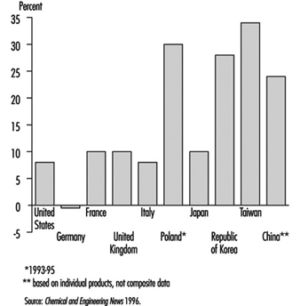
Much of the chemical industry is highly capital-intensive and is also strongly dependent on research and development (e.g., pharmaceuticals). The combined result of these two factors is that the industry employs an abnormally low number of unskilled manual workers for its size, in comparison with manufacturing industry in general. Total employment in the industry rose slightly during the period of rapid growth prior to 1970, but since then the drive for increased productivity has resulted in a decline in employment in the chemical industry in most developed countries. Table 1 shows chemical industry employment in the United States and several European countries for 1995.
Table 1. Chemical industry employment in selected countries (1995)
|
Country |
Employment |
|
United States |
1, 045,000 |
|
Germany |
538,000 |
|
France |
248,000 |
|
United Kingdom |
236,000 |
|
Italy |
191,000 |
|
Poland |
140,000 |
|
Spain |
122,000 |
Source: Chemical and Engineering News 1996.
Impacts of Disasters: Lessons From a Medical Perspective
This article was adapted, with permission, from Zeballos 1993b.
Latin America and the Caribbean have not been spared their share of natural disasters. Almost every year catastrophic events cause deaths, injuries and enormous economic damage. Overall, it is estimated that the major natural disasters of the last two decades in this region caused property losses affecting nearly 8 million people, some 500,000 injuries and 150,000 deaths. These figures rely heavily on official sources. (It is quite difficult to obtain accurate information in sudden-onset disasters, because there are multiple information sources and no standardized information system.) The Economic Commission for Latin America and the Caribbean (ECLAC) estimates that during an average year, disasters in Latin America and the Caribbean cost US$1.5 billion and take 6,000 lives (Jovel 1991).
Table 1 lists major natural disasters that struck countries of the region in the 1970-93 period. It should be noted that slow- onset disasters, such as droughts and floods, are not included.
Table 1. Major disasters in Latin America and the Caribbean, 1970-93
|
Year |
Country |
Type of |
No.of deaths |
Est. no. of |
|
1970 |
Peru |
Earthquake |
66,679 |
3,139,000 |
|
1972 |
Nicaragua |
Earthquake |
10,000 |
400,000 |
|
1976 |
Guatemala |
Earthquake |
23,000 |
1,200,000 |
|
1980 |
Haiti |
Hurricane (Allen) |
220 |
330,000 |
|
1982 |
Mexico |
Volcanic eruption |
3,000 |
60,000 |
|
1985 |
Mexico |
Earthquake |
10,000 |
60,000 |
|
1985 |
Colombia |
Volcanic eruption |
23,000 |
200,000 |
|
1986 |
El Salvador |
Earthquake |
1,100 |
500,000 |
|
1988 |
Jamaica |
Hurricane (Gilbert) |
45 |
500,000 |
|
1988 |
Mexico |
Hurricane (Gilbert) |
250 |
200,000 |
|
1988 |
Nicaragua |
Hurricane (Joan) |
116 |
185,000 |
|
1989 |
Montserrat, |
Hurricane (Hugo) |
56 |
220,000 |
|
1990 |
Peru |
Earthquake |
21 |
130,000 |
|
1991 |
Costa Rica |
Earthquake |
51 |
19,700 |
|
1992 |
Nicaragua |
Tsunami |
116 |
13,500 |
|
1993 |
Honduras |
Tropical storm |
103 |
11,000 |
Source: PAHO 1989; OFDA (USAID),1989; UNDRO 1990.
Economic Impact
In recent decades, ECLAC has carried out extensive research on the social and economic impacts of disasters. This has clearly demonstrated that disasters have negative repercussions on social and economic development in developing countries. Indeed, the monetary losses caused by a major disaster often exceed the total annual gross income of the affected country. Not surprisingly, such events can paralyze affected countries and foster widespread political and social turmoil.
In essence, disasters have three kinds of economic impacts:
- direct impacts on the affected population’s property
- indirect impacts caused by lost economic production and services
- secondary impacts that become apparent after the disaster—such as reduced national income, increased inflation, foreign trade problems, heightened financial expenses, a resulting fiscal deficit, decreased monetary reserves and so on (Jovel 1991).
Table 2 shows the estimated losses caused by six major natural disasters. While such losses might not seem particularly devastating for developed countries with strong economies, they can have a serious and lasting impact on the weak and vulnerable economies of developing countries (PAHO 1989).
Table 2. Losses due to six natural disasters
|
Disaster |
Location |
Year(s) |
Total losses |
|
Earthquake |
Mexico |
1985 |
4,337 |
|
Earthquake |
El Salvador |
1986 |
937 |
|
Earthquake |
Ecuador |
1987 |
1,001 |
|
Volcanic eruption (Nevado del Ruiz) |
Colombia |
1985 |
224 |
|
Floods, drought (“El Niño”) |
Peru, Ecuador, Bolivia |
1982-83 |
3,970 |
|
Hurricane (Joan) |
Nicaragua |
1988 |
870 |
Source: PAHO 1989; ECLAC.
The Health Infrastructure
In any major disaster-related emergency, the first priority is to save lives and provide immediate emergency care for the injured. Among the emergency medical services mobilized for these purposes, hospitals play a key role. Indeed, in countries with a standardized emergency response system (one where the concept of “emergency medical services” encompasses provision of emergency care through the coordination of independent subsystems involving paramedics, fire-fighters and rescue teams) hospitals constitute the major component of that system (PAHO 1989).
Hospitals and other health care facilities are densely occupied. They house patients, personnel and visitors, and they operate 24 hours a day. Patients may be surrounded by special equipment or connected to life-support systems dependent on power supplies. According to project documents available from the Inter-American Development Bank (IDB) (personal communication, Tomas Engler, IDB), the estimated cost of one hospital bed in a specialized hospital varies from country to country, but the average runs from US$60,000 to US$80,000 and is greater for highly specialized facilities.
In the United States, particularly California, with its extensive experience in seismic-resistant engineering, the cost of one hospital bed can exceed US$110,000. In sum, modern hospitals are highly complex facilities combining the functions of hotels, offices, laboratories and warehouses (Peisert et al. 1984; FEMA 1990).
These health care facilities are highly vulnerable to hurricanes and earthquakes. This has been amply demonstrated by past experience in Latin America and the Caribbean. For example, as table 3 shows, just three disasters of the 1980s damaged 39 hospitals and destroyed some 11,332 hospital beds in El Salvador, Jamaica and Mexico. Besides damage to these physical plants at critical times, the loss of human life (including the death of highly qualified local professionals with promising futures) needs to be considered (see table 4 and table 5).
Table 3. Number of hospitals and hospital beds damaged or destroyed by three major natural disasters
|
Type of disaster |
No. of hospitals |
No. of beds lost |
|
Earthquake, Mexico (Federal District, September 1985) |
13 |
4,387 |
|
Earthquake, El Salvador (San Salvador, October 1986) |
4 |
1,860 |
|
Hurricane Gilbert (Jamaica, September 1988) |
23 |
5,085 |
|
Total |
40 |
11,332 |
Source: PAHO 1989; OFDA(USAID) 1989; ECLAC.
Table 4. Victims in two hospitals collapsed by the 1985 earthquake in Mexico
|
Collapsed hospitals |
||||
|
General hospital |
Juarez hospital |
|||
|
Number |
% |
Number |
% |
|
|
Fatalities |
295 |
62.6 |
561 |
75.8 |
|
Rescued |
129 |
27.4 |
179 |
24.2 |
|
Missing |
47 |
10.0 |
– |
– |
|
Total |
471 |
100.0 |
740 |
100.0 |
Source: PAHO 1987.
Table 5. Hospital beds lost as a result of the March 1985 Chilean earthquake
|
Region |
No. of existing hospitals |
No. of beds |
Beds lost in region |
|
|
No. |
% |
|||
|
Metropolitan Area |
26 |
11,464 |
2,373 |
20.7 |
|
Region 5 (Viña del Mar, Valparaíso, |
23 |
4,573 |
622 |
13.6 |
|
Region 6 (Rancagua) |
15 |
1,413 |
212 |
15.0 |
|
Region 7 (Ralca, Meula) |
15 |
2,286 |
64 |
2.8 |
|
Total |
79 |
19,736 |
3,271 |
16.6 |
Source: Wyllie and Durkin 1986.
At present the ability of many Latin American hospitals to survive earthquake disasters is uncertain. Many such hospitals are housed in old structures, some dating from Spanish colonial times; and while many others occupy contemporary buildings of appealing architectural design, lax application of building codes makes their ability to resist earthquakes questionable.
Risk Factors in Earthquakes
Of the various types of sudden natural disasters, earthquakes are by far the most damaging to hospitals. Of course, each earthquake has its own characteristics relating to its epicentre, type of seismic waves, geological nature of the soil through which the waves travel and so on. Nevertheless, studies have revealed certain common factors that tend to cause death and injuries and certain others that tend to prevent them. These factors include structural characteristics related to building failure, various factors related to human behaviour and certain characteristics of nonstructural equipment, furnishings and other items inside buildings.
In recent years, scholars and planners have been paying special attention to identification of risk factors affecting hospitals, in hopes of framing better recommendations and norms to govern the building and organization of hospitals in highly vulnerable zones. A brief listing of relevant risk factors is shown in table 6. These risk factors, particularly those related to the structural aspects, were observed to influence patterns of destruction during a December 1988 earthquake in Armenia that killed some 25,000 people, affected 1,100,000 and destroyed or severely damaged 377 schools, 560 health facilities and 324 community and cultural centres (USAID 1989).
Table 6. Risk factors associated with earthquake damage to hospital infrastructure
|
Structural |
Non-structural |
Behavioural |
|
Design |
Medical equipment |
Public information |
|
Quality of construction |
Laboratory equipment |
Motivation |
|
|
Office equipment |
Plans |
|
Materials |
Cabinets, shelves |
Educational programmes |
|
Soil conditions |
Stoves, refrigerators, heaters |
Health care staff training |
|
Seismic characteristics |
X-ray machines |
|
|
Time of the event |
Reactive materials |
|
|
Population density |
|
|
Damage on a similar scale occurred in June 1990, when an earthquake in Iran killed about 40,000 people, injured 60,000 others, left 500,000 homeless, and collapsed 60 to 90% of buildings in affected zones (UNDRO 1990).
To address these and like calamities, an international seminar was held in Lima, Peru, in 1989 on the planning, design, repair and management of hospitals in earthquake-prone areas. The seminar, sponsored by PAHO, Peru’s National University of Engineering and the Peruvian-Japanese Center for Seismic Research (CISMID), brought together architects, engineers and hospital administrators to study issues related to health facilities located in these areas. The seminar approved a core of technical recommendations and commitments directed at carrying out vulnerability analyses of hospital infrastructures, improving the design of new facilities and establishing safety measures for existing hospitals, with emphasis on those located in high-risk earthquake areas (CISMID 1989).
Recommendations on Hospital Preparedness
As the foregoing suggests, hospital disaster preparedness constitutes an important component of PAHO’s Office of Emergency Preparedness and Disaster Relief. Over the last ten years, member countries have been encouraged to pursue activities directed toward this end, including the following:
- classifying hospitals according to their risk factors and vulnerabilities
- developing internal and external hospital response plans and training personnel
- developing contingency plans and establishing safety measures for the professional and technical hospital staffs
- strengthening lifeline backup systems that help hospitals to function during emergency situations.
More broadly, a principal aim of the current International Decade for Natural Disaster Reduction (IDNDR) is to attract, motivate and commit national health authorities and policy-makers around the world, thereby encouraging them to strengthen the health services directed at coping with disasters and to reduce the vulnerability of those services in the developing world.
Issues Concerning Technological Accidents
During the last two decades, developing countries have entered into intense competition to achieve industrial development. The main reasons for this competition are as follows:
- to attract capital investment and to generate jobs
- to satisfy domestic demand for products at a lower cost and to alleviate dependency on the international market
- to compete with international and subregional markets
- to establish foundations for development.
Unfortunately, efforts made have not always resulted in obtaining the intended objectives. In effect, flexibility in attracting capital investment, lack of sound regulation with respect to industrial safety and environmental protection, negligence in the operation of industrial plants, use of obsolete technology, and other aspects have contributed to increasing the risk of technological accidents in certain areas.
In addition, the lack of regulation regarding the establishment of human settlements near or around industrial plants is an additional risk factor. In major Latin American cities it is common to see human settlements practically surrounding industrial complexes, and the inhabitants of these settlements are ignorant of the potential risks (Zeballos 1993a).
In order to avoid accidents such as those that occurred in Guadalajara (Mexico) in 1992, the following guidelines are suggested for the establishment of chemical industries, to protect industrial workers and the population at large:
- selection of appropriate technology and study of alternatives
- appropriate location of industrial plants
- regulation of human settlements in the neighbourhood of industrial plants
- security considerations for technology transfer
- routine inspection of industrial plants by local authorities
- expertise provided by specialized agencies
- role of workers in compliance with security rules
- rigid legislation
- classification of toxic materials and close supervision of their use
- public education and training of workers
- establishment of response mechanisms in case of emergency
- training of health workers in emergency plans for technological accidents.
Case Study: The Kader Toy Factory Fire
A tragic industrial fire in Thailand has focused worldwide attention on the need to adopt and enforce state-of-the-art codes and standards in industrial occupancies.
On May 10, 1993, a major fire at the Kader Industrial (Thailand) Co. Ltd. factory located in the Nakhon Pathom Province of Thailand killed 188 workers (Grant and Klem 1994). This disaster stands as the world’s worst accidental loss-of-life fire in an industrial building in recent history, a distinction held for 82 years by the Triangle Shirtwaist factory fire that killed 146 workers in New York City (Grant 1993). Despite the years between these two disasters, they share striking similarities.
Various domestic and international agencies have focused on this incident following its occurrence. With respect to fire protection concerns, the National Fire Protection Association (NFPA) cooperated with the International Labour Organization (ILO) and with the Bangkok Police Fire Brigade in documenting this fire.
Questions for a Global Economy
In Thailand, the Kader fire has created a great deal of interest about the country’s fire safety measures, particularly its building code design requirements and enforcement policies. Thai Prime Minister Chuan Leekpai, who travelled to the scene on the evening of the fire, has pledged that the government will address fire safety issues. According to the Wall Street Journal (1993), Leekpai has called for tough action against those who violate the safety laws. Thai Industry Minister Sanan Kachornprasart is quoted as saying that “Those factories without fire prevention systems will be ordered to install one, or we will shut them down”.
The Wall Street Journal goes on to state that labour leaders, safety experts and officials say that the Kader fire may help tighten building codes and safety regulations, but they fear that lasting progress is still far off as employers flout rules and governments allow economic growth to take priority over worker safety.
Because the majority of the shares of Kader Industrial (Thailand) Co. Ltd. are owned by foreign interests, the fire has also fuelled international debate about foreign investors’ responsibilities for ensuring the safety of the workers in their sponsoring country. Twenty per cent of the Kader shareholders are from Taiwan, and 79.96% are from Hong Kong. A mere 0.04% of Kader is owned by Thai nationals.
Moving into a global economy implies that products are manufactured at one location and used at other locations throughout the world. Desire for competitiveness in this new market should not lead to compromise in fundamental industrial fire safety provisions. There is a moral obligation to provide workers with an adequate level of fire protection, no matter where they are located.
The Facility
The Kader facility, which manufactured stuffed toys and plastic dolls primarily intended for export to the United States and other developed countries, is located in the Sam Phran District of Nakhon Pathom Province. This is not quite halfway between Bangkok and the nearby city of Kanchanaburi, the site of the infamous Second World War railroad bridge over the River Kwai.
The structures that were destroyed in the blaze were all owned and operated directly by Kader, which owns the site. Kader has two sister companies that also operate at the location on a lease arrangement.
The Kader Industrial (Thailand) Co. Ltd. was first registered on 27 January 1989, but the company’s licence was suspended on 21 November 1989, after a fire on 16 August 1989 destroyed the new plant. This fire was attributed to the ignition of polyester fabric used in the manufacture of dolls in a spinning machine. After the plant was rebuilt, the Ministry of Industry allowed it to reopen on 4 July 1990.
Between the time the factory reopened and the May 1993 fire, the facility experienced several other, smaller fires. One of them, which occurred in February 1993, did considerable damage to Building Three, which was still being repaired at the time of the fire in May 1993. The February fire occurred late at night in a storage area and involved polyester and cotton materials. Several days after this blaze a labour inspector visited the site and issued a warning that pointed out the plant’s need for safety officers, safety equipment and an emergency plan.
Initial reports following the May 1993 fire noted that there were four buildings on the Kader site, three of which were destroyed by the fire. In a sense this is true, but the three buildings were actually a single E-shaped structure (see figure 1), the three primary portions of which were designated Buildings One, Two and Three. Nearby was a one-storey workshop and another four-storey structure referred to as Building Four.
Figure 1. Site plan of the Kader toy factory
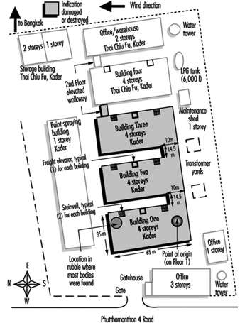
The E-shaped building was a four-storey structure composed of concrete slabs supported by a structural steel frame. There were windows around the perimeter of each floor and the roof was a gently sloped, peaked arrangement. Each portion of the building had a freight elevator and two stairwells that were each 1.5 metres (3.3 feet) wide. The freight elevators were caged assemblies.
Each building at the plant was equipped with a fire alarm system. None of the buildings had automatic sprinklers, but portable extinguishers and hose stations were installed on outside walls and in the stairwells of each building. None of the structural steel in the building was fireproofed.
There is conflicting information about the total number of workers at the site. The Federation of Thai Industries had pledged to help 2,500 plant employees displaced by the fire, but it is unclear how many employees were at the site at any one time. When the fire occurred, it was reported that there were 1,146 workers in Building One. Thirty-six were on the first floor, 10 were on the second, 500 were on the third, and 600 were on the fourth. There were 405 workers in Building Two. Sixty of them were on the first floor, 5 were on the second, 300 were on the third and 40 were on the fourth. It is not clear how many workers were in Building Three since a portion of it was still being refurbished. Most of the workers at the plant were women.
The Fire
Monday, May 10, was a normal workday at the Kader facility. At approximately 4:00 p.m., as the end of the day shift approached, someone discovered a small fire on the first floor near the south end of Building One. This portion of the building was used to package and store the finished products, so it contained a considerable fuel load (see figure 2). Each building at the facility had a fuel load composed of fabric, plastics and materials used for stuffing, as well as other normal workplace materials.
Figure 2. Internal layout of buildings one, two and three
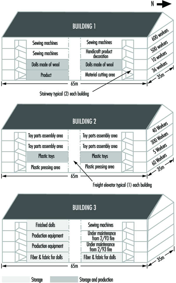
Security guards in the vicinity of the fire tried unsuccessfully to extinguish the flames before they called the local police fire brigade at 4:21 p.m. Authorities received two more calls, at 4:30 p.m. and 4:31 p.m. The Kader facility is just beyond the jurisdictional boundaries of Bangkok, but fire apparatus from Bangkok, as well as apparatus from Nakhon Pathom Province, responded.
As the workers and security guards tried in vain to extinguish the fire, the building began filling with smoke and other products of combustion. Survivors reported that the fire alarm never sounded in Building One, but many workers grew concerned when they saw smoke on the upper floors. Despite the smoke, security guards reportedly told some workers to stay at their stations because it was a small fire that would soon be under control.
The fire spread rapidly throughout Building One, and the upper floors soon became untenable. The blaze blocked the stairwell at the south end of the building, so most of the workers rushed to the north stairwell. This meant that approximately 1,100 people were trying to leave the third and fourth floors through a single stairwell.
The first fire apparatus arrived at 4:40 p.m., their response time having been extended because of the relatively remote location of the facility and the gridlock conditions typical of Bangkok traffic. Arriving fire-fighters found Building One heavily involved in flames and already beginning to collapse, with people jumping from the third and fourth floors.
Despite the fire-fighters’ efforts, Building One collapsed completely at approximately 5:14 p.m. Fanned by strong winds blowing toward the north, the blaze spread quickly into Buildings Two and Three before the fire brigade could effectively defend them. Building Two reportedly collapsed at 5:30 p.m., and Building Three at 6:05 p.m. The fire brigade successfully kept the fire from entering Building Four and the smaller, one-storey workshop nearby, and the fire-fighters had the blaze under control by 7:45 p.m. Approximately 50 pieces of fire apparatus were involved in the battle.
The fire alarms in Buildings Two and Three reportedly functioned properly, and all the workers in those two buildings escaped. The workers in Building One were not so fortunate. A large number of them jumped from the upper floors. In all, 469 workers were taken to the hospital, where 20 died. The other dead were found during the post-fire search of what had been the north stairwell of the building. Many of them apparently succumbed to lethal products of combustion before or during the building’s collapse. According to the latest information available, 188 people, most of them female, have died as a result of this fire.
Even with the help of six large hydraulic cranes that were moved to the site to facilitate the search for victims, it was several days before all the bodies could be removed from the rubble. There were no fatalities among the fire-fighters, although there was one injury.
Traffic in the vicinity, which is normally congested, made transporting the victims to hospitals difficult. Nearly 300 injured workers were taken to the nearby Sriwichai II Hospital, although many of them were transferred to alternate medical facilities when the number of victims exceeded the hospital’s capacity to treat them.
The day after the fire, Sriwichai II Hospital reported that it had kept 111 fire victims. The Kasemrat Hospital received 120; Sriwichai Pattanana received 60; Sriwichai I received 50; Ratanathibet I received 36; Siriraj received 22; and Bang Phai received 17. The remaining 53 injured workers were sent to various other medical facilities in the area. In all, 22 hospitals throughout Bangkok and Nakhon Pathom Province participated in treating victims of the disaster.
Sriwichai II Hospital reported that 80% of their 111 victims suffered serious injuries and that 30% required surgery. Half of the patients suffered only from smoke inhalation, while the remainder also suffered burns and fractures that ranged from broken ankles to fractured skulls. At least 10% of the injured Kader workers admitted to Sriwichai II Hospital risk permanent paralysis.
Determining the cause of this fire became a challenge because the portion of the facility in which it began was totally destroyed and the survivors have provided conflicting information. Since the fire started near a large electrical control panel, investigators first thought that problems with the electrical system might have been the cause. They also considered arson. At this time, however, Thai authorities feel that a carelessly discarded cigarette may have been the source of ignition.
Analysing the Fire
For 82 years, the world has recognized the 1911 Triangle Shirtwaist factory fire in New York City as the worst accidental loss-of-life industrial fire in which the fatalities were limited to the building of fire origin. With 188 fatalities, however, the Kader factory fire now replaces the Triangle fire in the record books.
When analysing the Kader fire, a direct comparison with the Triangle fire provides a useful benchmark. The two buildings were similar in a number of ways. The arrangement of the exits was poor, the fixed fire protection systems were insufficient or ineffective, the initial fuel package was readily combustible, and the horizontal and vertical fire separations were inadequate. In addition, neither company had provided its workers with adequate fire safety training. However, there is one distinct difference between these two fires: the Triangle Shirtwaist factory building did not collapse and the Kader buildings did.
Inadequate exit arrangements were perhaps the most significant factor in the high loss of life at both the Kader and the Triangle fires. Had the exiting provisions of NFPA 101, the Life Safety Code, which was established as a direct result of the Triangle fire, been applied at the Kader facility, substantially fewer lives would have been lost (NFPA 101, 1994).
Several fundamental requirements of the Life Safety Code pertain directly to the Kader fire. For example, the Code requires that every building or structure be constructed, arranged and operated in such a way that its occupants are not placed in any undue danger by fire, smoke, fumes or the panic that may occur during an evacuation or during the time it takes to defend the occupants in place.
The Code also requires that every building have enough exits and other safeguards of the proper size and at the proper locations to provide an escape route for every occupant of a building. These exits should be appropriate to the individual building or structure, taking into account the character of the occupancy, the capabilities of the occupants, the number of occupants, the fire protection available, the height and type of building construction and any other factor necessary to provide all the occupants with a reasonable degree of safety. This was obviously not the case in the Kader facility, where the blaze blocked one of Building One’s two stairwells, forcing approximately 1,100 people to flee the third and fourth floors through a single stairwell.
In addition, the exits should be arranged and maintained so that they provide free and unobstructed egress from all parts of a building whenever it is occupied. Each of these exits should be clearly visible, or the route to every exit should be marked in such a way that every occupant of the building who is physically and mentally able readily knows the direction of escape from any point.
Every vertical exit or opening between the floors of a building should be enclosed or protected as necessary to keep the occupants reasonably safe while they exit and to prevent fire, smoke and fumes from spreading from floor to floor before the occupants have had a chance to use the exits.
The outcomes of both the Triangle and the Kader fires were significantly affected by the lack of adequate horizontal and vertical fire separations. The two facilities were arranged and built in such a way that a fire on a lower floor could spread rapidly to the upper floors, thus trapping a large number of workers.
Large, open work spaces are typical of industrial facilities, and fire-rated floors and walls must be installed and maintained to slow the spread of fire from one area to another. Fire also must be kept from spreading externally from the windows on one floor to those on another floor, as it did during the Triangle fire.
The most effective way to limit vertical fire spread is to enclose stairwells, elevators, and other vertical openings between floors. Reports of features such as caged freight elevators at the Kader factory raise significant questions about the ability of the buildings’ passive fire protection features to prevent vertical spread of fire and smoke.
Fire Safety Training and Other Factors
Another factor that contributed to the large loss of life in both the Triangle and Kader fires was the lack of adequate fire safety training, and the rigid security procedures of both companies.
After the fire at the Kader facility, survivors reported that fire drills and fire safety training were minimal, although the security guards had apparently had some incipient fire training. The Triangle Shirtwaist factory had no evacuation plan, and fire drills were not implemented. Furthermore, post-fire reports from Triangle survivors indicate that they were routinely stopped as they left the building at the end of the work day for security purposes. Various post-fire accusations by Kader survivors also imply that security arrangements slowed their exit, although these accusations are still being investigated. In any case, the lack of a well-understood evacuation plan seems to have been an important factor in the high loss of life sustained in the Kader fire. Chapter 31 of the Life Safety Code addresses fire drills and evacuation training.
The absence of fixed automatic fire protection systems also affected the outcome of both the Triangle and the Kader fires. Neither facility was equipped with automatic sprinklers, although the Kader buildings did have a fire alarm system. According to the Life Safety Code, fire alarms should be provided in buildings whose size, arrangement or occupancy make it unlikely that the occupants themselves will notice a fire immediately. Unfortunately, the alarms reportedly never operated in Building One, which resulted in a significant delay in evacuation. There were no fatalities in Buildings Two and Three, where the fire alarm system functioned as intended.
Fire alarm systems should be designed, installed and maintained in accordance with documents like NFPA 72, the National Fire Alarm Code (NFPA 72, 1993). Sprinkler systems should be designed and installed in accordance with documents like NFPA 13, Installation of Sprinkler Systems, and maintained in accordance with NFPA 25, Inspection, Testing, and Maintenance of Water-Based Fire Protection Systems (NFPA 13, 1994; NFPA 25, 1995).
The initial fuel packages in both the Triangle and Kader fires were similar. The Triangle fire started in rag bins and quickly spread to combustible clothing and garments before involving wood furnishings, some of which were impregnated with machine oil. The initial fuel package at the Kader plant consisted of polyester and cotton fabrics, various plastics, and other materials used to manufacture stuffed toys, plastic dolls, and other related products. These are materials that can typically be ignited easily, can contribute to rapid fire growth and spread, and have a high heat release rate.
Industry will probably always handle materials that have challenging fire protection characteristics, but manufacturers should recognize these characteristics and take the necessary precautions to minimize associated hazards.
The Building’s Structural Integrity
Probably the most notable difference between the Triangle and Kader fires is the effect they had on the structural integrity of the buildings involved. Even though the Triangle fire gutted the top three floors of the ten-storey factory building, the building remained structurally intact. The Kader buildings, on the other hand, collapsed relatively early in the fire because their structural steel supports lacked the fireproofing that would have allowed them to maintain their strength when exposed to high temperatures. A post-fire review of the debris at the Kader site showed no indication that any of the steel members had been fireproofed.
Obviously, building collapse during a fire presents a great threat to both the building’s occupants and to the fire-fighters involved in controlling the blaze. However, it is unclear whether the collapse of the Kader building had any direct effect on the number of fatalities, since the victims may have already succumbed to the effects of heat and products of combustion by the time the building collapsed. If the workers on the upper floors of Building One had been shielded from the products of combustion and heat while they were trying to escape, the building’s collapse would have been a more direct factor in the loss of life.
Fire Focused Attention on Fire Protection Principles
Among the fire protection principles on which the Kader fire has focused attention are exit design, occupant fire safety training, automatic detection and suppression systems, fire separations and structural integrity. These lessons are not new. They were first taught more than 80 years ago at the Triangle Shirtwaist fire and again, more recently, in a number of other fatal workplace fires, including those at the chicken-processing plant in Hamlet, North Carolina, USA, that killed 25 workers; at a doll factory in Kuiyong, China, that killed 81 workers; and at the electrical power plant in Newark, New Jersey, USA, that killed all 3 workers in the plant (Grant and Klem 1994; Klem 1992; Klem and Grant 1993).
The fires in North Carolina and New Jersey, in particular, demonstrate that the mere availability of state-of-the-art codes and standards, such as NFPA’s Life Safety Code, cannot prevent tragic losses. These codes and standards must also be adopted and rigorously enforced if they are to have any effect.
National, state and local public authorities should examine the way they enforce their building and fire codes to determine whether new codes are needed or existing codes need to be updated. This review should also determine whether a building plan review and inspection process is in place to ensure that the appropriate codes are followed. Finally, provisions must be made for periodic follow-up inspections of existing buildings to ensure that the highest levels of fire protection are maintained throughout the life of the building.
Building owners and operators must also be aware that they are responsible for ensuring that their employees’ working environment is safe. At the very least, the state-of-the-art fire protection design reflected in fire codes and standards must be in place to minimize the possibility of a catastrophic fire.
Had the Kader buildings been equipped with sprinklers and working fire alarms, the loss of life might not have been so high. Had Building One’s exits been better designed, hundreds of people might not have been injured jumping from the third and fourth floors. Had vertical and horizontal separations been in place, the fire might not have spread so quickly throughout the building. Had the buildings’ structural steel members been fireproofed, the buildings might not have collapsed.
Philosopher George Santayana has written: “Those who forget the past are condemned to repeat it.” The Kader Fire of 1993 was unfortunately, in many ways, a repeat of the Triangle Shirtwaist Fire of 1911. As we look to the future, we need to recognize all that we need to do, as a global society, to prevent history from repeating itself.
Occupational Health and Safety Measures in Agricultural Areas Contaminated by Radionuclides: The Chernobyl Experience
Massive contamination of agricultural lands by radionuclides occurs, as a rule, due to large accidents at the enterprises of nuclear industry or nuclear power stations. Such accidents occurred at Windscale (England) and South Ural (Russia). The largest accident happened in April 1986 at the Chernobyl nuclear power station. The latter entailed intensive contamination of soils over several thousands of square kilometres.
The major factors contributing to radiation effects in agricultural areas are as follows:
- whether radiation is from a single or a long-term exposure
- total quantity of radioactive substances entering the environment
- ratio of radionuclides in the fallout
- distance from the source of radiation to agricultural lands and settlements
- hydrogeological and soil characteristics of agricultural lands and the purpose of their use
- peculiarities of work of the rural population; diet, water supply
- time since the radiological accident.
As a result of the Chernobyl accident more than 50 million Curies (Ci) of mostly volatile radionuclides entered the environment. At the first stage, which covered 2.5 months (the “iodine period”), iodine-131 produced the greatest biological hazard, with significant doses of high-energy gamma radiation.
Work on agricultural lands during the iodine period should be strictly regulated. Iodine-131 accumulates in the thyroid gland and damages it. After the Chernobyl accident, a zone of very high radiation intensity, where no one was permitted to live or work, was defined by a 30 km radius around the station.
Outside this prohibited zone, four zones with various rates of gamma radiation on the soils were distinguished according to which types of agricultural work could be performed; during the iodine period, the four zones had the following radiation levels measured in roentgen (R):
- zone 1—less than 0.1 mR/h
- zone 2—0.1 to 1 mR/h
- zone 3—1.0 to 5 mR/h
- zone 4—5 mR/h and more.
Actually, due to the “spot” contamination by radionuclides over the iodine period, agricultural work in these zones was performed at levels of gamma irradiation from 0.2 to 25 mR/h. Apart from uneven contamination, variation in gamma radiation levels was caused by different concentrations of radionuclides in different crops. Forage crops in particular are exposed to high levels of gamma emitters during harvesting, transportation, ensilage and when they are used as fodder.
After the decay of iodine-131, the major hazard for agricultural workers is presented by the long-lived nuclides caesium-137 and strontium-90. Caesium-137, a gamma emitter, is a chemical analogue of potassium; its intake by humans or animals results in uniform distribution throughout the body and it is relatively quickly excreted with urine and faeces. Thus, the manure in the contaminated areas is an additional source of radiation and it must be removed as quickly as possible from stock farms and stored in special sites.
Strontium-90, a beta emitter, is a chemical analogue of calcium; it is deposited in bone marrow in humans and animals. Strontium-90 and caesium-137 can enter the human body through contaminated milk, meat or vegetables.
The division of agricultural lands into zones after the decay of short-lived radionuclides is carried out according to a different principle. Here, it is not the level of gamma radiation, but the amount of soil contamination by caesium-137, strontium-90 and plutonium-239 that are taken into account.
In the case of particularly severe contamination, the population is evacuated from such areas and farm work is performed on a 2-week rotation schedule. The criteria for zone demarcation in the contaminated areas are given in table 1.
Table 1. Criteria for contamination zones
|
Contamination zones |
Soil contamination limits |
Dosage limits |
Type of action |
|
1. 30 km zone |
– |
– |
Residing of |
|
2. Unconditional |
15 (Ci)/km2 |
0.5 cSv/year |
Agricultural work is performed with 2-week rotation schedule under strict radiological control. |
|
3. Voluntary |
5–15 Ci/km2 |
0.01–0.5 |
Measures are undertaken to reduce |
|
4. Radio- ecological |
1–5 Ci/km2 |
0.01 cSv/year |
Agricultural work is |
When people work on agricultural lands contaminated by radionuclides, the intake of radionuclides by the body through respiration and contact with soil and vegetable dusts may occur. Here, both beta emitters (strontium-90) and alpha emitters are extremely dangerous.
As a result of accidents at nuclear power stations, part of radioactive materials entering the environment are low-dispersed, highly active particles of the reactor fuel—“hot particles”.
Considerable amounts of dust containing hot particles are generated during agricultural work and in windy periods. This was confirmed by the results of investigations of tractor air filters taken from machines which were operated on the contaminated lands.
The assessment of dose loads on the lungs of agricultural workers exposed to hot particles revealed that outside the 30 km zone the doses amounted to several millisieverts (Loshchilov et al. 1993).
According to the data of Bruk et al. (1989) the total activity of caesium-137 and caesium-134 in the inspired dust in machine operators amounted to 0.005 to 1.5 nCi/m3. According to their calculations, over the total period of field work the effective dose to lungs ranged from 2 to
70 cSv.
The relation between the amount of soil contamination by caesium-137 and radioactivity of work zone air was established. According to the data of the Kiev Institute for Occupational Health it was found that when the soil contamination by caesium-137 amounted to 7.0 to 30.0 Ci/km2 the radioactivity of the breathing zone air reached 13.0 Bq/m3. In the control area, where the density of contamination amounted to 0.23 to 0.61 Ci/km3, the radioactivity of work zone air ranged from 0.1 to 1.0 Bq/m3 (Krasnyuk, Chernyuk and Stezhka 1993).
The medical examinations of agricultural machine operators in the “clear” and contaminated zones revealed an increase in cardiovascular diseases in workers in the contaminated zones, in the form of ischaemic heart disease and neurocirculatory dystonia. Among other disorders dysplasia of the thyroid gland and an increased level of monocytes in the blood were registered more frequently.
Hygienic Requirements
Work schedules
After large accidents at nuclear power stations, temporary regulations for the population are usually adopted. After the Chernobyl accident temporary regulations for a period of one year were adopted, with the TLV of 10 cSv. It is assumed that workers receive 50% of their dose due to external radiation during work. Here, the threshold of intensity of radiation dose over the eight-hour work day should not exceed 2.1 mR/h.
During agricultural work, the radiation levels at workplaces can fluctuate significantly, depending on the concentrations of radioactive substances in soils and plants; they also fluctuate during technological processing (siloing, preparation of dry fodder and so on). In order to reduce dosages to workers, regulations of time limits for agricultural work are introduced. Figure 1 shows regulations which were introduced after the Chernobyl accident.
Figure 1. Time limits for agricultural work depending on intensity of gamma-ray radiation at workplaces.
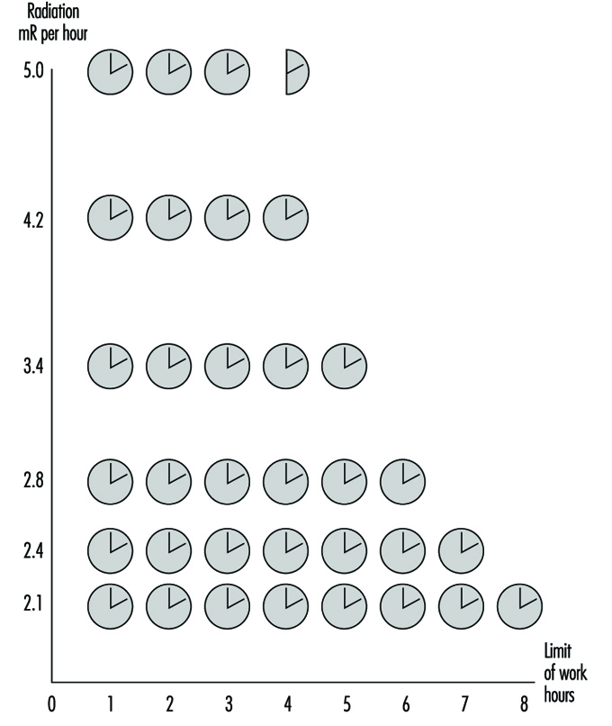
Agrotechnologies
When carrying out agricultural work in conditions of high contamination of soils and plants, it is necessary to strictly observe measures directed at prevention of dust contamination. The loading and unloading of dry and dusty substances should be mechanized; the neck of the conveyer tube should be covered with fabric. Measures directed at the decrease of dust release must be undertaken for all types of field work.
Work using agricultural machinery should be carried out taking due account of cabin pressurization and the choice of the proper direction of operation, with the wind at the side being preferable. If possible it is desirable to first water the areas being cultivated. The wide use of industrial technologies is recommended so as to eliminate manual work on the fields as much as possible.
It is appropriate to apply substances to the soils which can promote absorption and fixation of radionuclides, changing them into insoluble compounds and thus preventing the transfer of radionuclides into plants.
Agricultural machinery
One of the major hazards for the workers is agricultural machinery contaminated by radionuclides. The allowable work time on the machines depends on the intensity of gamma radiation emitted from the cabin surfaces. Not only is the thorough pressurization of cabins required, but due control over ventilation and air conditioning systems as well. After work, wet cleaning of cabins and replacement of filters should be carried out.
When maintaining and repairing the machines after decontamination procedures, the intensity of gamma radiation at the outer surfaces should not exceed 0.3 mR/h.
Buildings
Routine wet cleaning should be done inside and outside buildings. Buildings should be equipped with showers. When preparing fodder which contains dust components, it is necessary to adhere to procedures aimed at prevention of dust intake by the workers, as well as to keep the dust off the floor, equipment and so on.
Pressurization of the equipment should be under control. Workplaces should be equipped with effective general ventilation.
Use of pesticides and mineral fertilizers
The application of dust and granular pesticides and mineral fertilizers, as well as spraying from aeroplanes, should be restricted. Machine spraying and application of granular chemicals as well as liquid mixed fertilizers are preferable. The dust mineral fertilizers should be stored and transported only in tightly closed containers.
Loading and unloading work, preparation of pesticide solutions and other activities should be performed using maximum individual protective equipment (overalls, helmets, goggles, respirators, rubber gauntlets and boots).
Water supply and diet
There should be special closed premises or motor vans without draughts where workers can take their meals. Before taking meals workers should clean their clothes and thoroughly wash their hands and faces with soap and running water. During summer periods field workers should be supplied with drinking water. The water should be kept in closed containers. Dust must not enter containers when filling them with water.
Preventive medical examinations of workers
Periodic medical examinations should be carried out by a physician; laboratory analysis of blood, ECG and tests of respiratory function are compulsory. Where radiation levels do not exceed permissible limits, the frequency of medical examinations should be not less than once every 12 months. Where there are higher levels of ionizing radiation the examinations should be carried out more frequently (after sowing, harvesting and so on) with due account of radiation intensity at workplaces and the total absorbed dose.
Organization of Radiological Control over Agricultural Areas
The major indices characterizing the radiological situation after fallout are gamma radiation intensity in the area, contamination of agricultural lands by the selected radionuclides and content of radionuclides in agricultural products.
The determination of gamma radiation levels in the areas allows the drawing of the borders of severely contaminated areas, estimation of doses of external radiation to people engaged in agricultural work and the establishing of corresponding schedules providing for radiological safety.
The functions of radiological monitoring in agriculture are usually the responsibility of radiological laboratories of the sanitary service as well as veterinary and agrochemical radiological laboratories. The training and education of the personnel engaged in dosimetric control and consultations for the rural population are carried out by these laboratories.
Environmental and Public Health Issues
Aerospace industries have been significantly affected by the enormous growth in environmental and community noise regulations passed primarily in the United States and Europe since the 1970s. Legislation such as the Clean Water Act, the Clean Air Act and the Resource Conservation and Recovery Act in the United States and companion Directives in the European Union have resulted in voluminous local regulations to meet environmental quality objectives. These regulations typically enforce the use of best available technology, whether new materials or processes or end of stack control equipment. Additionally, universal issues such as ozone depletion and global warming are forcing changes to traditional operations by banning chemicals such as chlorofluorocarbons entirely unless exceptional conditions exist.
Early legislation had little impact on aerospace operations until the 1980s. The continued growth of the industry and the concentration of operations around airports and industrialized areas made regulation attractive. The industry underwent a revolution in terms of programmes required to track and manage toxic emissions to the environment with the intent to ensure safety. Wastewater treatment from metal finishing and aircraft maintenance became standard at all large facilities. Hazardous waste segregation, classification, manifesting and, later, treatment prior to disposal were instituted where rudimentary programmes had previously existed. Clean-up programmes at disposal sites became major economic issues for many companies as costs rose to many millions at each site. In the later 1980s and early 1990s, air emissions, which constitute as much as 80% or more of the total emissions from aircraft manufacturing and operation, became the focus of regulation. The International Civil Aviation Organization (ICAO) adopted engine emission standards as early as 1981 (ICAO 1981).
Chemical emissions regulations affect essentially all chemical processing, engine and auxiliary power unit, fuelling and ground service vehicle operations. In Los Angeles, for example, ground-level ozone and carbon monoxide reductions to achieve Clean Air Act standards could require a reduction of 50% of flight operations at Los Angeles International Airport by the year 2005 (Donoghue 1994). Emissions there will be tracked daily to ensure limits on total emissions of volatile organic compounds and carbon monoxide are below the overall total permitted. In Sweden, a tax has been levied on aircraft carbon dioxide emissions due to their global warming potential. Similar regulations in some regions have resulted in a near total elimination of vapour degreasing using chlorinated solvents such as trichloroethane due to the historically high levels of emissions from open-topped degreasers and the ozone depleting potential and toxicity of 1,1,1 trichloroethane.
Perhaps the most broad-based regulation yet imposed is the Aerospace National Emission Standard for Hazardous Air Pollutants (NESHAP) of 1995, promulgated by the United States Environmental Protection Agency under the Clean Air Act Amendments of 1990. This regulation requires all aerospace operations to comply with the average of the best 12% of the current United States control practices to reduce the emission of pollutants from the processes of greatest emissions. The standard requires compliance by September 1998. The processes and materials most affected are manual wipe and flush cleaning, primers and topcoats, paint removal and chemical milling maskants. The regulation allows process change or control and charges local authorities with enforcement of material, equipment, work practice and record-keeping requirements. The significance of these rules is the imposition of the best practices with little regard to cost on every aerospace manufacturer. They force a comprehensive change to low vapour pressure solvent cleaning materials and to coatings low in solvent content, as well as application equipment technology as shown in table 1. Some exceptions were made where product safety or personnel safety (due to fire hazard and so on) would be compromised.
Table 1. Summary of the United States NESHAP in manufacturing and reworking facilities.
| Process | Requirements1 |
| Manual wipe cleaning of aerospace components |
Maximum composite pressure of 45 mmHg at 20 °C or use of specific preferred cleaners Exemptions for confined spaces, work near energized systems, etc. Immediate enclosure of wipers to contain further evaporation |
| Flush cleaning with VOCs2 or HAPs3 containing materials | Collection and containment of fluids |
| Application of primers and topcoats | Use of high transfer efficiencyequipment4 |
| Primer HAP content less water | 350 g/l of primer as applied on average5 |
| Top coat HAP content water | 420 g/l of topcoat as applied on average5 |
| Exterior surface paint removal |
Zero HAP chemicals, mechanical blast, high-intensity light6. Allowance for 6 assembled aircraft to be depainted per site/year with HAP-containing chemicals |
| Coatings containing inorganic HAPs | High efficiency control of particulate emissions |
| Chemical milling mask HAP content less water | 160 g/l of material as applied or a high-efficiency vapour collection and control system |
| Overspray from coating operations with HAP | Multistage particulate filter |
| Air pollution control equipment | Minimum acceptable efficiencies plus monitoring |
| Spray gun cleaning | No atomization of cleaning solvent, provisions to capture waste |
1 Considerable record keeping, inspection and other requirements apply, not listed here.
2 Volatile organic compounds. These have been shown to be photochemical reactive and precursors to ground-level ozone formation.
3 Hazardous air pollutants. These are 189 compounds listed by the US Environmental Protection Agency as toxic.
4 Listed equipment includes electrostatic or high-volume, low-pressure (HVLP) spray guns.
5 Specialty coatings and other low-emission processes excluded.
6 Touch-up allowed using 26 gallons per aircraft per year of HAP-containing remover (commercial), or 50 gallons per year (military).
Source: US EPA Regulation: 40 CFR Part 63.
Summaries of typical chemical hazards and emission-control practices due to the impact of environmental regulations on manufacturing and maintenance operations in the United States are provided in table 2 and table 3 respectively. European regulations have for the most part not kept pace in the area of toxic air emissions, but have placed greater emphasis on the elimination of toxins, such as cadmium, from the products and the accelerated phase-out of ozone depleter compounds. The Netherlands require operators to justify the use of cadmium as essential for flight safety, for example.
Table 2. Typical chemical hazards of manufacturing processes.
| Common processes | Type of emission | Chemicals or hazards |
| Coatings, including temporary protective coatings, mask and paints |
Overspray of solids and evaporation of solvents
Solid waste, (e.g., wipers)
|
Volatile organic compouds (VOCs) including methyl ethyl ketone, toluene, xylenes Ozone-depleting compounds (ODCs) (chlorofluorocarbons, trichloroethane and others) Organic toxins including tricholorethane, xylene, toluene Inorganic toxins including cadmium, chromates, lead VOCs or toxins as above |
| Solvent cleaning |
Evaporation of solvents Solid waste (wipers) Liquid waste |
VOCs, ozone depletersor toxins VOCs or toxins Waste solvent (VOCs) and/or contaminated water |
| Paint removal |
Evaporation or entrainment of solvents
Corrosive liquid waste Dust, heat, light |
VOCs such as xylene, toluene, methyl ethyl ketone Organic toxins (methylene chloride, phenolics) Heavy metals (chromates) Caustics and acids including formic acid Toxic dust (blasting), heat (thermal stripping) and light |
| Anodizing aluminium |
Ventilation exhaust Liquid waste |
Acid mist Concentrated acid usually chromic, nitric and hydrofluoric |
| Plating hard metals |
Ventilation exhaust Rinsewaters |
Heavy metals, acids, complexed cyanides Heavy metals, acids, complexed cyanides |
| Chemical milling | Liquid waste | Caustics and heavy metals, other metals |
| Sealing |
Evaporated solvent Solid waste |
VOCs Heavy metals, trace amounts of toxic organics |
| Alodining (conversion coating) |
Liquid waste Solid waste |
Chromates, possibly complexed cyanide Chromates, oxidizers |
| Corrosion-inhibiting ompounds | Particulates, solid waste | Waxes, heavy metals and toxic organics |
| Composite fabrication | Solid waste | Uncured volatiles |
| Vapour degreasing | Escaped vapour | Tricholorethane, trichoroethylene, perchloroethylene |
| Aqueous degreasing | Liquid waste | VOCs, silicates, trace metals |
Table 3. Typical emission-control practices.
| Processes | Air emissions | Water emissions | Land emissions |
| Coating: overspray | Emission control equipment1 for overspray (VOCs and solid particulate) | Onsite pretreatment and monitoring | Treat and landfill3 paint-booth waste. Incinerate flammables and landfill ash. Recycle solvents where possible. |
| Solvent cleaning with VOCs | Emission controls2 and/or material substitution | Onsite pretreatment and monitoring | Incinerate and landfill used wipers |
| Solvent cleaning with ODCs | Substitution due to ban on ODCs production | None | None |
| Solvent cleaning with toxins | Substitution | Onsite pretreatment and monitoring | Treat to reduce toxicity4 and landfill |
| Paint removal | Emission controls or substitution with non-HAP or mechanical methods | Onsite pretreatment and monitoring | Treatment sludge stabilized and landfilled |
| Anodizing aluminium, plating hard metals, chemical milling and immersion conversion coating (Alodine) | Emission control (scrubbers) and/or substitution in some cases | Onsite pretreatment of rinsewaters. Acid and caustic concentrates treated on or off site | Treatment sludge stabilized and landfilled. Other solid waste treated and landfilled |
| Sealing | Usually none required | Usually none required | Incinerate and landfill used wipers |
| Corrosion-inhibiting compounds | Ventilation filtered | Usually none required | Wipers, residual compound and paint-booth filters5 treated and landfilled |
| Vapour degreasing | Chillers to recondense vapours Enclosed systems, or Activated carbon collection | Degreasing solvent separation from wastewater | Toxic degreasing solvent recycled, residual treated and landfilled |
| Aqueous degreasing | Usually none required | Onsite pretreatment and monitoring | Pretreatment sludge managed as hazardous waste |
1 Most aerospace facilities are required to own an industrial wastewater pretreatment facility. Some may have full treatment.
2 Control efficiency usually must be greater than 95% removal/destruction of incoming concentrations. Commonly 98% or greater is achieved by activated carbon or thermal oxidation units.
3 Strict regulations on landfilling specify treatment and landfill construction and monitoring.
4 Toxicity is measured by bioassay and/or leaching tests designed to predict results in solid waste landfills.
5 Usually filtered paint booths. Work done out of sequence or touch up, etc. is usually exempt due to practical considerations.
Noise regulations have followed a similar course. The United States Federal Aviation Administration and the International Civil Aviation Organization have set aggressive targets for the improvement of jet engine noise reduction (e.g., the United States Airport Noise and Capacity Act of 1990). Airlines are faced with the option of replacing older aircraft such as the Boeing 727 or McDonnell Douglas DC-9 (Stage 2 aircraft as defined by the ICAO) with new generation airplanes, re-engining or retrofitting these aircraft with “hush” kits. Elimination of noisy Stage 2 aircraft is mandated by 31 December 1999 in the United States, when Stage 3 rules take effect.
Another hazard posed by aerospace operation is the threat of falling debris. Items such as waste, aircraft parts and satellites descend with varying degrees of frequency. The most common in terms of frequency is the so-called blue ice which results when leaking toilet system drains allow waste to freeze outside the aircraft and then separate and fall. Aviation authorities are considering rules to require additional inspection and correction of leaking drains. Other hazards such as satellite debris may occasionally be hazardous (e.g., radioactive instruments or power sources), but present extremely low risk to the public.
Most companies have formed organizations to address emission reduction. Goals for environmental performance are established and policies are in place. Management of the permits, safe material handling and transportation, disposal and treatment require engineers, technicians and administrators.
Environmental engineers, chemical engineers and others are employed as researchers and administrators. In addition, programmes exist to help remove the source of chemical and noise emissions within the design or the process.
Controls and Health Effects
There is a growing market demand for the aerospace industry to decrease product development flow time while at the same time utilizing materials that meet increasingly stringent, and sometimes contradictory, performance criteria. Accelerated product testing and production may cause material and process development to outpace the parallel development of environmental health technologies. The result may be products which have been performance tested and approved but for which there exist insufficient data on health and environmental impact. Regulations such as the Toxic Substance Control Act (TSCA) in the United States require (1) testing of new materials; (2) the development of prudent lab practices for research and development testing; (3) restrictions on the import and export of certain chemicals; and
(4) monitoring of health, safety and environmental studies as well as company records for significant health effects from chemical exposures.
The increased use of material safety data sheets (MSDSs) has helped provide health professionals with the information required to control chemical exposures. However, complete toxicological data exist for only a few hundred of the thousands of materials in use, providing a challenge to industrial hygienists and toxicologists. To the extent feasible, local exhaust ventilation and other engineering controls should be used to control exposure, particularly when poorly understood chemicals or inadequately characterized contaminant generation rates are involved. Respirators can play a secondary role when supported by a well-planned and rigorously enforced respiratory protection management programme. Respirators and other personal protective equipment must be selected to offer fully adequate protection without producing undue discomfort to workers.
Hazard and control information must be effectively communicated to employees prior to a product’s introduction into the work area. Oral presentation, bulletins, videos or other means of communication may be used. The method of communication is important to the success of any workplace chemical introduction. In aerospace manufacturing areas, employees, materials and work processes change frequently. Hazard communication must therefore be a continuous process. Written communications are not likely to be effective in this environment without the support of more active methods such as crew meetings or video presentations. Provisions should always be made for responding to worker questions.
Extremely complex chemical environments are characteristic of airframe manufacturing facilities, particularly assembly areas. Intensive, responsive and well-planned industrial hygiene efforts are required to recognize and characterize hazards associated with the simultaneous or sequential presence of large numbers of chemicals, many of which may not have been adequately tested for health effects. The hygienist must be wary of contaminants released in physical forms not anticipated by the suppliers, and therefore not listed on MSDSs. For example, the repeated application and removal of strips of partially cured composite materials may release solvent-resin mixtures as an aerosol that will not be effectively measured using vapour-monitoring methods.
The concentration and combinations of chemicals may also be complex and highly variable. Delayed work performed out of normal sequence may result in hazardous materials being used without proper engineering controls or adequate personal protective measures. The variations in work practices between individuals and the size and configuration of different airframes may have a significant impact on exposures. Variations in solvent exposures among individuals performing wing tank cleaning have exceeded two orders of magnitude, due in part to the effects of body size on the flow of dilution air in extremely confined areas.
Potential hazards should be identified and characterized, and necessary controls implemented, before materials or processes enter the workplace. Safe usage standards must also be developed, established and documented with mandatory compliance before work begins. Where information is incomplete, it is appropriate to assume the highest reasonably expected risk and to provide appropriate protective measures. Industrial hygiene surveys should be performed at regular and frequent intervals to ensure that controls are adequate and working reliably.
The difficulty of characterizing aerospace workplace exposures necessitates close cooperation between hygienists, clinicians, toxicologists and epidemiologists (see table 1). The presence of a very well informed workforce and management cadre is also essential. Worker reporting of symptoms should be encouraged, and supervisors should be trained to be alert to signs and symptoms of exposure. Biological exposure monitoring may serve as an important supplement to air monitoring where exposures are highly variable or where dermal exposure may be significant. Biological monitoring can also be used to determine whether controls are effective in reducing employee uptake of contaminants. Analysis of medical data for patterns of signs, symptoms and complaints should be performed routinely.
Table 1. Technological development requirements for health, safety and environmental control for new processes and materials.
| Parameter |
Technological requirement |
| Airborne levels of contaminants |
Analytical methods for chemical quantification Air monitoring techniques |
| Potential health impact | Acute and chronic toxicology studies |
| Environmental fate | Bioaccumulation and biodegradation studies |
| Waste characterization | Chemical compatibility test Bioassays |
Paint hangars, aircraft fuselages and fuel tanks may be served by very high volume exhaust systems during intensive painting, sealing and cleaning operations. Residual exposures and the inability of these systems to direct air flow away from workers usually require the supplemental use of respirators. Local exhaust ventilation is required for smaller painting, metal treating and solvent cleaning operations, for laboratory chemical work and for some plastics lay-up work. Dilution ventilation is usually adequate only in areas with minimal chemical usage or as a supplement to local exhaust ventilation. Significant air exchanges during winter can result in excessively dry interior air. Poorly designed exhaust systems which direct excessive cool air flow over workers’ hands or backs in small parts assembly areas may worsen hand, arm and neck problems. In large, complex manufacturing areas, attention must be paid to properly locating ventilation exhaust and intake points to avoid re-entraining contaminants.
Precision manufacturing of aerospace products requires clear, organized and well controlled work environments. Containers, barrels and tanks containing chemicals must be labelled as to the potential hazards of the materials. First aid information must be readily available. Emergency response and spill control information also must be available on the MSDS or similar data sheet. Hazardous work areas must be placarded and access controlled and verified.
Health Effects of Composite Materials
Airframe manufacturers, in both the civilian and defence sectors, have come to rely increasingly on composite materials in the construction of both interior and structural components. Generations of composite materials have been increasingly integrated into production throughout the industry, particularly in the defence sector, where they are valued for their low radar reflectivity. This rapidly developing manufacturing medium typifies the problem of design technology outpacing public health efforts. Specific hazards of the resin or fabric component of the composite prior to combination and resin cure differs from the hazards of cured materials. Additionally, partially cured materials (pre-pregs) may continue to preserve the hazard characteristics of the resin components during the various steps leading to producing a composite part (AIA 1995). Toxicological considerations of major resin categories are provided in table 2.
Table 2. Toxicological considerations of major components of resins utilized in aerospace composite materials.1
| Resin type | Components 2 | Toxicological consideration |
| Epoxy | Amine curing agents, epichlorohydrin | Sensitizer, suspect carcinogen |
| Polyimide | Aldehyde monomer, phenol | Sensitizer, suspect carcinogen, systemic* |
| Phenolic | Aldehyde monomer, phenol | Sensitizer, suspect carcinogen, systemic* |
| Polyester | Styrene, dimethylaniline | Narcosis, central nervous system depression, cyanosis |
| Silicone | Organic siloxane, peroxides | Sensitizer, irritant |
| Thermoplastics** | Polystyrene, polyphenylene sulphide | Systemic*, irritant |
1 Examples of typical components of the uncured resins are provided. Other chemicals of diverse toxicological nature may be present as curing agents, diluents and additives.
2 Applies primarily to components of wet resin prior to reaction. Varying amounts of these materials are present in the partially cured resin, and trace quantities in the cured materials.
* Systemic toxicity, indicating effects produced in several tissues.
** Thermoplastics included as separate category, in that breakdown products listed are created during moulding operations when the polymerized starting material is heated.
The degree and type of hazard posed by composite materials depends primarily on the specific work activity and degree of resin cure as the material moves from a wet resin/fabric to the cured part. Release of volatile resin components may be significant prior to and during initial reaction of resin and curing agent, but may also occur during the processing of materials which go through more than one level of cure. The release of these components tends to be greater in elevated temperature conditions or in poorly ventilated work areas and may range from trace to moderate levels. Dermal exposure to the resin components in the pre-cure state is often an important part of total exposure and therefore should not be neglected.
Off-gassing of resin degradation products may occur during various machining operations which create heat at the surface of the cured material. These degradation products have yet to be fully characterized, but tend to vary in chemical structure as a function of both temperature and resin type. Particles may be generated by machining of cured materials or by cutting pre-pregs which contain residues of resin materials which are released when the material is disturbed. Exposure to gases produced by oven cure has been noted where, through improper design or faulty operation, autoclave exhaust ventilation fails to remove these gases from the work environment.
It should be noted that dusts created by new fabric materials containing fibreglass, kevlar, graphite or boron/metal oxide coatings are generally considered to be capable of producing mild to moderate fibrogenic reaction; so far we have been unable to characterize their relative potency. Additionally, information on the relative contribution of fibrogenic dusts from various machining operations is still under investigation. The various composite operations and hazards have been characterized (AIA 1995) and are listed in table 3.
Table 3. Hazards of chemicals in the aerospace industry.
| Chemical agent | Sources | Potential disease |
| Metals | ||
| Beryllium dust | Machining beryllium alloys | Skin lesions, acute or chronic lung disease |
| Cadmium dust, mist | Welding, burning, spray painting | Delayed acute pulmonary oedema, kidney damage |
| Chromium dust/mist/fumes | Spraying/sanding primer, welding | Cancer of the respiratory tract |
| Nickel | Welding, grinding | Cancer of the respiratory tract |
| Mercury | Laboratories, engineering tests | Central nervous system damage |
| Gases | ||
| Hydrogen cyanide | Electroplating | Chemical asphyxiation, chronic effects |
| Carbon monoxide | Heat treating, engine work | Chemical asphyxiation, chronic effects |
| Oxides of nitrogen | Welding, electroplating, pickling | Delayed acute pulmonary oedema, permanent lung damage (possible) |
| Phosgene | Welding decomposition of solvent vapour | Delayed acute pulmonary oedema, permanent lung damage (possible) |
| Ozone | Welding, high-altitude flight | Acute and chronic lung damage, cancer of the respiratory tract |
| Organic compounds | ||
| Aliphatic | Machine lubricants, fuels, cutting fluids | Follicular dermatitis |
| Aromatic, nitro and amino | Rubber, plastics, paints, dyes | Anaemia, cancer, skin sensitization |
| Aromatic,other | Solvents | Narcosis, liver damage, dermatitis |
| Halogenated | Depainting, degreasing | Narcosis, anaemia, liver damage |
| Plastics | ||
| Phenolics | Interior components, ducting | Allergic sensitization, cancer (possible) |
| Epoxy (amine hardeners) | Lay-up operations | Dermatitis, allergic sensitization, cancer |
| Polyurethane | Paints, internal components | Allergic sensitization, cancer (possible) |
| Polyimide | Structural components | Allergic sensitization, cancer (possible) |
| Fibrogenic dusts | ||
| Asbestos | Military and older aircraft | Cancer, asbestosis |
| Silica | Abrasive blasting, fillers | Silicosis |
| Tungsten carbide | Precision tool grinding | Pneumoconiosis |
| Graphite, kevlar | Composite machining | Pneumoconiosis |
| Benign dusts (possible) | ||
| Fibreglass | Insulating blankets, interior components | Skin and respiratory irritation, chronic disease (possible) |
| Wood | Mock-up and model making | Allergic sensitization, respiratory cancer |
Aircraft Engine Manufacturing
The manufacture of aircraft engines, whether piston or jet, involves the conversion of raw materials into extremely reliable precision machines. The highly stressed operating environments associated with air transport require the use of a broad range of high-strength materials. Both conventional and unique manufacturing methods are utilized.
Construction Materials
Aircraft engines are primarily constructed of metallic components, although recent years have seen the introduction of plastic composites for certain parts. Various aluminium and titanium alloys are used where strength and light weight are of primary importance (structural components, compressor sections, engine frames). Chromium, nickel and cobalt alloys are used where resistance to high temperature and corrosion are required (combustor and turbine sections). Numerous steel alloys are used in intermediate locations.
Since weight minimization on aircraft is a critical factor in reducing life-cycle costs (maximizing payload, minimizing fuel consumption), advanced composite materials have recently been introduced as light-weight replacements for aluminium, titanium and some steel alloys in structural parts and ductwork where high temperatures are not experienced. These composites consist primarily of polyimide, epoxy and other resin systems, reinforced with woven fibreglass or graphite fibres.
Manufacturing Operations
Virtually every common metalworking and machining operation is used in aircraft engine manufacture. This includes hot forging (airfoils, compressor disks), casting (structural components, engine frames), grinding, broaching, turning, drilling, milling, shearing, sawing, threading, welding, brazing and others. Associated processes involve metal finishing (anodizing, chromating and so on), electroplating, heat treating and thermal (plasma, flame) spraying. The high strength and hardness of the alloys used, combined with their complex shapes and precision tolerances, necessitate more challenging and rigorous machining requirements than other industries.
Some of the more unique metalworking processes include chemical and electrochemical milling, electro-discharge machining, laser drilling and electron-beam welding. Chemical and electrochemical milling involve the removal of metal from large surfaces in a manner which retains or creates a contour. The parts, depending upon their specific alloy, are placed in a highly concentrated controlled acid, caustic or electrolyte bath. Metal is removed by the chemical or electrochemical action. Chemical milling is often used after forging of airfoils to bring wall thicknesses into specification while maintaining the contour.
Electro-discharge machining and laser drilling are typically used for making small-diameter holes and intricate contours in hard metals. Many such holes are required in combustor and turbine components for cooling purposes. Metal removal is accomplished by high-frequency thermo-mechanical action of electro-spark discharges. The process is carried out in a dielectric mineral oil bath. The electrode serves as the reverse image of the desired cut.
Electron-beam welding is used to join parts where deep weld penetration is required in hard-to-reach geometries. The weld is generated by a focused, accelerated beam of electrons within a vacuum chamber. The kinetic energy of the electrons striking the work-piece is transformed into heat for welding.
Composite plastic fabrication involves either “wet” lay-up techniques or the use of pre-impregnated cloths. With wet lay-up, the viscous uncured resin mixture is spread over a tooling form or mould by either spraying or brushing. The fibre reinforcement material is manually laid into the resin. Additional resin is applied to obtain uniformity and contour with the tooling form. The completed lay-up is then cured in an autoclave under heat and pressure. Pre-impregnated materials consist of semi-rigid, ready-to-use, partially-cured sheets of resin-fibre composites. The material is cut to size, manually moulded to the contours of the tooling form and cured in an autoclave. Cured parts are conventionally machined and assembled into the engine.
Inspection and Testing
In order to assure the reliability of aircraft engines, a number of inspection, testing and quality-control procedures are performed during the fabrication and on the final product. Common non-destructive inspection methods include radiographic, ultrasonic, magnetic particle and fluorescent penetrant. They are used to detect any cracks or internal flaws within the parts. Assembled engines are usually tested in instrumented test cells prior to customer delivery.
Health and Safety Hazards and Their Control Methods
Health hazards associated with aircraft engine manufacture are primarily related to the toxicity of the materials used and their potential for exposure. Aluminium, titanium and iron are not considered significantly toxic, while chromium, nickel and cobalt are more problematic. Certain compounds and valence states of the latter three metals have indicated carcinogenic properties in humans and animals. Their metallic forms are generally not considered as toxic as their ionic forms, typically found in metal finishing baths and paint pigments.
In conventional machining, most operations are performed using coolants or cutting fluids which minimize the generation of airborne dust and fumes. With the exception of dry grinding, the metals usually do not present inhalation hazards, although there is concern about the inhalation of coolant mists. A fair amount of grinding is performed, particularly on jet engine parts, to blend contours and bring airfoils into their final dimensions. Small, hand-held grinders are typically used. Where such grinding is performed on chromium-, nickel- or cobalt-based alloys, local ventilation is required. This includes down-draft tables and self-ventilating grinders. Dermatitis and noise are additional health hazards associated with conventional machining. Employees will have varying degrees of skin contact with coolants and cutting fluids in the course of fixing, inspecting and removing parts. Repeated skin contact may manifest itself in various forms of dermatitis in some employees. Generally, protective gloves, barrier creams and proper hygiene will minimize such cases. High noise levels are often present when machining thin-walled, high-strength alloys, due to tool chatter and part vibration. This can be controlled to an extent through more rigid tooling, dampening materials, modifying machining parameters and maintaining sharp tools. Otherwise, PPE (e.g., ear muffs, plugs) is required.
Safety hazards associated with conventional machining operations mainly involve potential for physical injuries due to the point-of-operation, fixing and power transmission drive movements. Control is accomplished through such methods as fixed guards, interlocked access doors, light curtains, pressure-sensitive mats and employee training and awareness. Eye protection should always be used around machining operations for protection from flying chips, particles and splashes of coolants and cleaning solvents.
Metal-finishing operations, chemical milling, electrochemical milling and electroplating involve open surface tank exposures to concentrated acids, bases and electrolytes. Most of the baths contain high concentrations of dissolved metals. Depending upon bath operating conditions and composition (concentration, temperature, agitation, size), most will require some form of local ventilation to control airborne levels of gases, vapours and mists. Various lateral, slot-type hood designs are commonly used for control. Ventilation designs and operating guidelines for different types of baths are available through technical organizations such as the American Conference of Governmental Industrial Hygienists (ACGIH) and the American National Standards Institute (ANSI). The corrosive nature of these baths dictates the use of eye and skin protection (splash goggles, face shields, gloves, aprons and so on) when working around these tanks. Emergency eyewashes and showers must also be available for immediate use.
Electron-beam welding and laser drilling present radiation hazards to workers. Electron-beam welding generates secondary x-ray radiation (bremsstrahlung effect). In a sense, the welding chamber constitutes an inefficient x-ray tube. It is critical that the chamber be constructed of material or contain shielding which will attenuate the radiation to the lowest practical levels. Lead shielding is often used. Radiation surveys should be periodically performed. Lasers present ocular and skin (thermal) hazards. Also, there is potential for exposure to the metal fumes produced by the evaporation of the base metal. Beam hazards associated with laser operations should be isolated and contained, where possible, within interlocked chambers. A comprehensive programme should be rigorously followed. Local ventilation should be provided where metal fumes are generated.
The major hazards related to the fabrication of composite plastic parts involve chemical exposure to unreacted resin components and solvents during wet lay-up operations. Of particular concern are aromatic amines used as reactants in polyimide resins and hardeners in epoxy resin systems. A number of these compounds are confirmed or suspected human carcinogens. They also exhibit other toxic effects. The highly reactive nature of these resin systems, particularly epoxies, gives rise to skin and respiratory sensitization. Control of hazards during wet lay-up operations should include local ventilation and extensive use of personal protective equipment to prevent skin contact. Lay-up operations using pre-impregnated sheets usually do not present airborne exposures, but skin protection should be used. Upon curing, these parts are relatively inert. They no longer present the hazards of their constituent reactants. Conventional machining of the parts, though, can produce nuisance dusts of an irritant nature, associated with the composite reinforcement materials (fibreglass, graphite). Local ventilation of the machining operation is often required.
Health hazards associated with test operations usually involve radiation (x or gamma rays) from radiographic inspection and noise from final product tests. Radiographic operations should include a comprehensive radiation safety programme, complete with training, badge monitoring and periodic surveys. Radiographic inspection chambers should be designed with interlocked doors, operating lights, emergency shut-offs and proper shielding. Test areas or cells where assembled products are tested should be acoustically treated, particularly for jet engines. Noise levels at the control consoles should be controlled to below 85 dBA. Provisions should also be made to prevent any build-up of exhaust gases, fuel vapours or solvents in the test area.
In addition to the aforementioned hazards related to specific operations, there are several others worthy of note. They include exposure to cleaning solvents, paints, lead and welding operations. Cleaning solvents are used throughout manufacturing operations. There has been a recent trend away from the use of chlorinated and fluorinated solvents to aqueous, terpine, alcohol and mineral spirit types due to toxicity and ozone depletion effects. Although the latter group may tend to be more environmentally acceptable, they often present fire hazards. Quantities of any flammable or combustible solvents should be limited in the workplace, used only from approved containers and with adequate fire protection in place. Lead is sometimes used in airfoil forging operations as a die lubricant. If so, a comprehensive lead control and monitoring programme should be in effect due to lead’s toxicity. Many types of conventional welding are used in manufacturing operations. Metal fumes, ultraviolet radiation and ozone exposures need to be evaluated for such operations. The need for controls will depend upon the specific operating parameters and metals involved.
" DISCLAIMER: The ILO does not take responsibility for content presented on this web portal that is presented in any language other than English, which is the language used for the initial production and peer-review of original content. Certain statistics have not been updated since the production of the 4th edition of the Encyclopaedia (1998)."