- You are here:
-
Home

-
Contents (2)
-
Part XVII. Services and Trade
-
Transport Industry and Warehousing
-
Storage
- Markowitz, Adrienne

Gerecke, Kenneth
Address: Occupational Safety and Health Administration, Country: United States Department of Labor, Gateway Building, Suite 2100, 3535 Market Street, Philadelphia, Pennsylvania 19104
Country: United States
Phone: 1 (215) 596-1201
Fax: 1 (215) 596-4872
Education: CIH, MS, 1975, New York University
Machine Safeguarding
There seem to be as many potential hazards created by moving machine parts as there are different types of machines. Safeguards are essential to protect workers from needless and preventable machinery-related injuries. Therefore, any machine part, function or process which may cause injury should be safeguarded. Where the operation of a machine or accidental contact with it can injure the operator or others in the vicinity, the hazard must be either controlled or eliminated.
Mechanical Motions and Actions
Mechanical hazards typically involve dangerous moving parts in the following three basic areas:
- the point of operation, that point where work is performed on the material, such as cutting, shaping, punching, stamping, boring or forming of stock
- power transmission apparatus, any components of the mechanical system which transmit energy to the parts of the machine performing the work. These components include flywheels, pulleys, belts, connecting rods, couplings, cams, spindles, chains, cranks and gears
- other moving parts, all parts of the machine which move while the machine is working, such as reciprocating, rotating and transversely moving parts, as well as feed mechanisms and auxiliary parts of the machine.
A wide variety of mechanical motions and actions which may present hazards to workers include the movement of rotating members, reciprocating arms, moving belts, meshing gears, cutting teeth and any parts that impact or shear. These different types of mechanical motions and actions are basic to nearly all machines, and recognizing them is the first step toward protecting workers from the hazards they may present.
Motions
There are three basic types of motion: rotating, reciprocating and transverse.
Rotating motion can be dangerous; even smooth, slowly rotating shafts can grip clothing and force an arm or hand into a dangerous position. Injuries due to contact with rotating parts can be severe (see figure 1).
Figure 1. Mechanical punch press
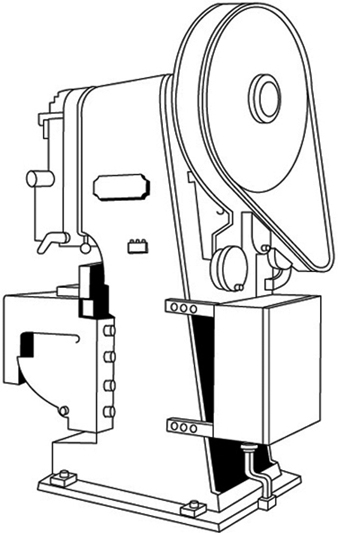
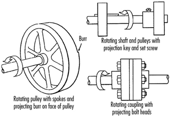
Collars, couplings, cams, clutches, flywheels, shaft ends, spindles and horizontal or vertical shafting are some examples of common rotating mechanisms which may be hazardous. There is added danger when bolts, nicks, abrasions and projecting keys or set screws are exposed on rotating parts on machinery, as shown in figure 2.
Figure 2. Examples of hazardous projections on rotating parts
In-running nip points are created by rotating parts on machinery. There are three main types of in-running nip points:
- Parts with parallel axes can rotate in opposite directions. These parts may be in contact (thereby producing a nip point) or in close proximity to each other, in which case the stock fed between the rolls produces the nip points. This danger is common on machinery with intermeshing gears, rolling mills and calenders, as shown in figure 3.
- Another type of nip point is created between rotating and tangentially moving parts, such as the point of contact between a power transmission belt and its pulley, a chain and a sprocket, or a rack and pinion, as shown in figure 4.
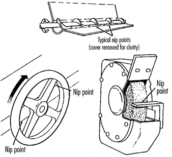
- Nip points can also occur between rotating and fixed parts which create a shearing, crushing or abrading action. Examples include handwheels or flywheels with spokes, screw conveyors or the periphery of an abrasive wheel and an incorrectly adjusted work rest, as shown in figure 5.
Figure 3. Common nip points on rotating parts
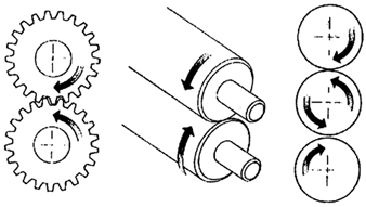
Figure 4. Nip points between rotating elements and parts with longitudinal motions
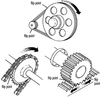
Figure 5. Nip points between rotating machine components
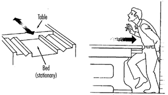
Reciprocating motions may be hazardous because during the back-and-forth or up-and-down motion, a worker may be struck by or caught between a moving part and a stationary part. An example is shown in figure 6.
Figure 6. Hazardous reciprocating motion
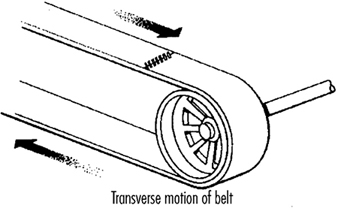
Transverse motion (movement in a straight, continuous line) creates a hazard because a worker may be struck or caught in a pinch or shear point by a moving part. An example of transverse motion is shown in figure 7.
Figure 7. Example of transverse motion
Actions
There are four basic types of action: cutting, punching, shearing and bending.
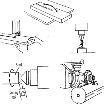
Cutting action involves rotating, reciprocating or transverse motion. Cutting action creates hazards at the point of operation where finger, head and arm injuries can occur and where flying chips or scrap material can strike the eyes or face. Typical examples of machines with cutting hazards include band saws, circular saws, boring or drilling machines, turning machines (lathes) and milling machines. (See figure 8.)
Figure 8. Examples of cutting hazards
Punching action results when power is applied to a slide (ram) for the purpose of blanking, drawing or stamping metal or other materials. The danger of this type of action occurs at the point of operation where stock is inserted, held and withdrawn by hand. Typical machines which use punching action are power presses and iron workers. (See figure 9.)
Figure 9. Typical punching operation
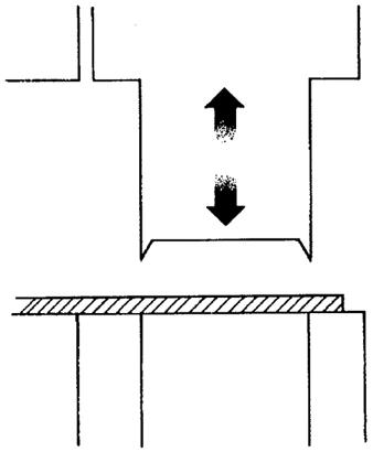
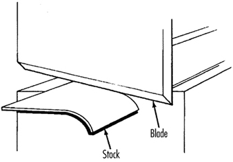
Shearing action involves applying power to a slide or knife in order to trim or shear metal or other materials. A hazard occurs at the point of operation where stock is actually inserted, held and withdrawn. Typical examples of machinery used for shearing operations are mechanically, hydraulically or pneumatically powered shears. (See figure 10.)
Figure 10. Shearing operation
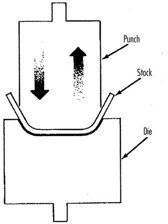
Bending action results when power is applied to a slide in order to shape, draw or stamp metal or other materials. The hazard occurs at the point of operation where stock is inserted, held and withdrawn. Equipment that uses bending action includes power presses, press brakes and tubing benders. (See figure 11.)
Figure 11. Bending operation
Requirements for Safeguards
Safeguards must meet the following minimum general requirements to protect workers against mechanical hazards:
Prevent contact. The safeguard must prevent hands, arms or any part of a worker’s body or clothing from making contact with dangerous moving parts by eliminating the possibility of the operators or other workers placing parts of their bodies near hazardous moving parts.
Provide security. Workers should not be able to easily remove or tamper with the safeguard. Guards and safety devices should be made of durable material that will withstand the conditions of normal use and that are firmly secured to the machine.
Protect from falling objects. The safeguard should ensure that no objects can fall into moving parts and damage the equipment or become a projectile that could strike and injure someone.
Not create new hazards. A safeguard defeats its purpose if it creates a hazard of its own, such as a shear point, a jagged edge or an unfinished surface. The edges of guards, for example, should be rolled or bolted in such a way that they eliminate sharp edges.
Not create interference. Safeguards which impede workers from performing their jobs might soon be overridden or disregarded. If possible, workers should be able to lubricate machines without disengaging or removing safeguards. For example, locating oil reservoirs outside the guard, with a line leading to the lubrication point, will reduce the need to enter the hazardous area.
Safeguard Training
Even the most elaborate safeguarding system cannot offer effective protection unless workers know how to use it and why. Specific and detailed training is an important part of any effort to implement safeguarding against machine-related hazards. Proper safeguarding may improve productivity and enhance efficiency since it may relieve workers’ apprehensions about injury. Safeguard training is necessary for new operators and maintenance or set-up personnel, when any new or altered safeguards are put in service, or when workers are assigned to a new machine or operation; it should involve instruction or hands-on training in the following:
- a description and identification of the hazards associated with particular machines and the specific safeguards against each hazard
- how the safeguards provide protection; how to use the safeguards and why
- how and under what circumstances safeguards can be removed, and by whom (in most cases, repair or maintenance personnel only)
- what to do (e.g., contact the supervisor) if a safeguard is damaged, missing or unable to provide adequate protection.
Methods of Machine Safeguarding
There are many ways to safeguard machinery. The type of operation, the size or shape of stock, the method of handling, the physical layout of the work area, the type of material and production requirements or limitations will help to determine the appropriate safeguarding method for the individual machine. The machine designer or safety professional must choose the most effective and practical safeguard available.
Safeguards may be categorized under five general classifications: (1) guards, (2) devices, (3) separation, (4) operations and (5) other.
Safeguarding with guards
There are four general types of guards (barriers which prevent access to danger areas), as follows:
Fixed guards. A fixed guard is a permanent part of the machine and is not dependent upon moving parts to perform its intended function. It may be constructed of sheet metal, screen, wire cloth, bars, plastic or any other material that is substantial enough to withstand whatever impact it may receive and to endure prolonged use. Fixed guards are usually preferable to all other types because of their relative simplicity and permanence (see table 1).
Table 1. Machine guards
|
Method |
Safeguarding action |
Advantages |
Limitations |
|
Fixed |
· Provides a barrier |
· Suits many specific applications |
· May interfere with visibility |
|
Interlocked |
· Shuts off or disengages power and prevents starting of machine when guard is open; should require the machine to be stopped before the worker can reach into the danger area |
· Provides maximum protection |
· Requires careful adjustment and maintenance |
|
Adjustable |
· Provides a barrier which may be adjusted to facilitate a variety of production operations |
· Can be constructed to suit many specific applications |
· Operator may enter danger area: protection may not be complete at all times |
|
Self-adjusting |
· Provides a barrier which moves according to the size of the stock entering danger area |
· Off-the-shelf guards are commercially available |
· Does not always provide maximum protection |
In figure 12, a fixed guard on a power press completely encloses the point of operation. The stock is fed through the side of the guard into the die area, with the scrap stock exiting on the opposite side.
Figure 12. Fixed guard on power press
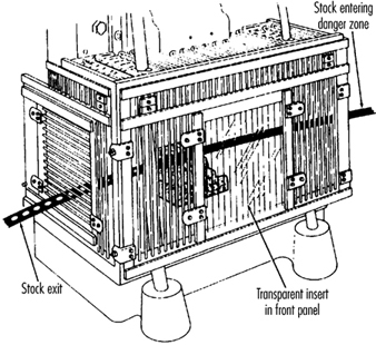
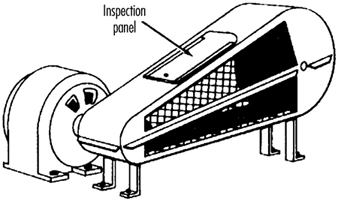
Figure 13 depicts a fixed enclosure guard which shields the belt and pulley of a power transmission unit. An inspection panel is provided on top to minimize the need for removing the guard.
Figure 13. Fixed guard enclosing belts and pulleys
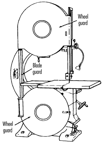
In figure 14, fixed enclosure guards are shown on a bandsaw. These guards protect operators from the turning wheels and moving saw blade. Normally, the only time the guards would be opened or removed would be for a blade change or for maintenance. It is very important that they be securely fastened while the saw is in use.
Figure 14. Fixed guards on band-saw
Interlocked guards. When interlocked guards are opened or removed, the tripping mechanism and/or power automatically shuts off or disengages, and the machine cannot cycle or be started until the interlock guard is back in place. However, replacing the interlock guard should not automatically restart the machine. Interlocked guards may use electrical, mechanical, hydraulic or pneumatic power, or any combination of these. Interlocks should not prevent “inching” (i.e., gradual progressive movements) by remote control, if required.
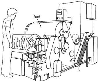
An example of an interlocking guard is shown in figure 15. In this figure, the beater mechanism of a picker machine (used in the textile industry) is covered by an interlocked barrier guard. This guard cannot be raised while the machine is running, nor can the machine be restarted with the guard in the raised position.
Figure 15. Interlocked guard on picker machine
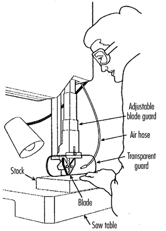
Adjustable guards. Adjustable guards allow flexibility in accommodating various sizes of stock. Figure 16 shows an adjustable enclosure guard on a band-saw.
Figure 16. Adjustable guard on band-saw
Self-adjusting guards. The openings of self-adjusting guards are determined by the movement of the stock. As the operator moves the stock into the danger area, the guard is pushed away, providing an opening which is large enough to admit only the stock. After the stock is removed, the guard returns to the rest position. This guard protects the operator by placing a barrier between the danger area and the operator. The guards may be constructed of plastic, metal or other substantial material. Self-adjusting guards offer different degrees of protection.
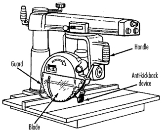
Figure 17 shows a radial-arm saw with a self-adjusting guard. As the blade is pulled across the stock, the guard moves up, staying in contact with the stock.
Figure 17. Self-adjusting guard on radial-arm saw
Safeguarding with devices
Safety devices may stop the machine if a hand or any part of the body is inadvertently placed in the danger area, may restrain or withdraw the operator’s hands from the danger area during operation, may require the operator to use both hands on machine controls simultaneously (thus keeping both hands and body out of danger) or may provide a barrier which is synchronized with the operating cycle of the machine in order to prevent entry to the danger area during the hazardous part of the cycle. There are five basic types of safety devices, as follows:
Presence-sensing devices
Three types of sensing devices which stop the machine or interrupt the work cycle or operation if a worker is within the danger zone are described below:
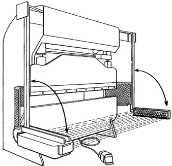
The photoelectric (optical) presence-sensing device uses a system of light sources and controls which can interrupt the machine’s operating cycle. If the light field is broken, the machine stops and will not cycle. This device should be used only on machines which can be stopped before the worker reaches the danger area. Figure 18 shows a photoelectric presence-sensing device used with a press brake. The device may be swung up or down to accommodate different production requirements.
Figure 18. Photoelectric presence-sensing device on press brake
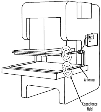
The radio-frequency (capacitance) presence-sensing device uses a radio beam that is part of the control circuit. When the capacitance field is broken, the machine will stop or will not activate. This device should be used only on machines which can be stopped before the worker can reach the danger area. This requires the machine to have a friction clutch or other reliable means for stopping. Figure 19 shows a radio-frequency presence-sensing device mounted on a part-revolution power press.
Figure 19. Radio-frequency presence-sensing device on power saw
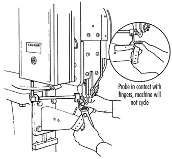
The electro-mechanical sensing device has a probe or contact bar which descends to a predetermined distance when the operator initiates the machine cycle. If there is an obstruction preventing it from descending its full predetermined distance, the control circuit does not actuate the machine cycle. Figure 20 shows an electro-mechanical sensing device on an eyeletter. The sensing probe in contact with the operator’s finger is also shown.
Figure 20. Electromechanical sensing device on eye-letter machine
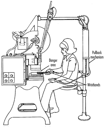
Pullback devices
Pullback devices utilize a series of cables attached to the operator’s hands, wrists and/or arms and are primarily used on machines with stroking action. When the slide/ram is up, the operator is allowed access to the point of operation. When the slide/ram begins to descend, a mechanical linkage automatically assures withdrawal of the hands from the point of operation. Figure 21 shows a pullback device on a small press.
Figure 21. Pullback device on power press
Restraint devices
Restraint devices, which utilize cables or straps that are attached between a fixed point and the operator’s hands, have been used in some countries. These devices are not generally considered to be acceptable safeguards because they are easily bypassed by the operator, thus allowing hands to be placed into the danger zone. (See table 2.)
Table 2. Devices
|
Method |
Safeguarding action |
Advantages |
Limitations |
|
Photoelectric |
· Machine will not start cycling when the light field is interrupted |
· Can allow freer movement for operator |
· Does not protect against mechanical failure |
|
Radio frequency |
· Machine cycling will not start when the capacitance field is interrupted |
· Can allow freer movement for operator |
· Does not protect against mechanical failure |
|
Electro-mechanical |
· Contact bar or probe travels a predetermined distance between the operator and the danger area |
· Can allow access at the point of operation |
· Contact bar or probe must be properly adjusted for each application; this adjustment must be maintained properly |
|
Pullback |
· As the machine begins to cycle, the operator’s hands are pulled out of the danger area |
· Eliminates the need for auxiliary barriers or other interference at the danger area |
· Limits movement of operator |
|
Safety trip controls: |
· Stops machine when tripped |
· Simplicity of use |
· All controls must be manually activated |
|
Two-hand control |
· Concurrent use of both hands is required, preventing the operator from entering the danger area |
· Operator’s hands are at a predetermined location away from danger area |
· Requires a partial cycle machine with a brake |
|
Two-hand trip |
· Concurrent use of two hands on separate controls prevent hands from being in danger area when machine cycle starts |
· Operator’s hands are away from danger area |
· Operator may try to reach into danger area after tripping machine |
|
Gate |
· Provides a barrier between danger area and operator or other personnel |
· Can prevent reaching into or walking into the danger area |
· May require frequent inspection and regular maintenance |
Safety control devices
All of these safety control devices are activated manually and must be manually reset to restart the machine:
- Safety trip controls such as pressure bars, trip rods and tripwires are manual controls which provide a quick means for deactivating the machine in an emergency situation.
- Pressure-sensitive body bars, when depressed, will deactivate the machine if the operator or anyone trips, loses balance or is drawn toward the machine. The positioning of the bar is critical, as it must stop the machine before a part of the body reaches the danger area. Figure 22 shows a pressure-sensitive body bar located on the front of a rubber mill.
Figure 22. Pressure-sensitive body bar on rubber mill

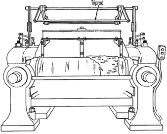
- Safety trip-rod devices deactivate the machine when pressed by hand. Because they have to be actuated by the operator during an emergency situation, their proper position is critical. Figure 23 shows a trip-rod located above the rubber mill.
Figure 23. Safety trip-rod on rubber mill
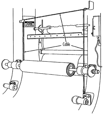
- Safety tripwire cables are located around the perimeter of, or near the danger area. The operator must be able to reach the cable with either hand to stop the machine. Figure 24 shows a calender equipped with this type of control.
Figure 24. Safety tripwire cable on calender
- Two-hand controls require constant, concurrent pressure for the operator to activate the machine. When installed on power presses, these controls use a part-revolution clutch and a brake monitor, as shown in figure 25. With this type of device, the operator’s hands are required to be at a safe location (on control buttons) and at a safe distance from the danger area while the machine completes its closing cycle.
Figure 25. Two-hand control buttons on part-revolution clutch power press

- Two-hand trip. The two-hand trip shown in figure 26 is usually used with machines equipped with full-revolution clutches. It requires concurrent application of both of the operator’s control buttons to activate the machine cycle, after which the hands are free. The trips must be placed far enough from the point of operation to make it impossible for operators to move their hands from the trip buttons or handles into the point of operation before the first half of the cycle is completed. The operator’s hands are kept far enough away to prevent them from being accidentally placed in the danger area before the slide/ram or blade reaches the full down position.
Figure 26. Two-hand control buttons on full-revolution clutch power press
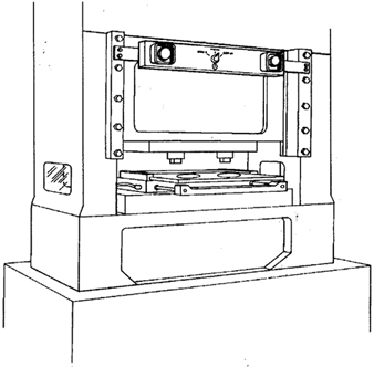
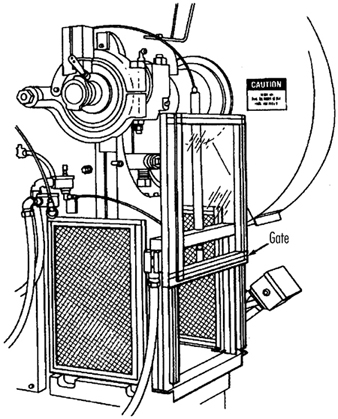
- Gates are safety control devices which provide a movable barrier that protects the operator at the point of operation before the machine cycle can be started. Gates are often designed to be operated with each machine cycle. Figure 27 shows a gate on a power press. If the gate is not permitted to descend to the fully closed position, the press will not function. Another application of gates is their use as a component of a perimeter safeguarding system, where the gates provide protection to the operators and to pedestrian traffic.
Figure 27. Power press with gate
Safeguarding by location or distance
To safeguard a machine by location, the machine or its dangerous moving parts must be so positioned that hazardous areas are not accessible or do not present a hazard to a worker during the normal operation of the machine. This may be accomplished with enclosure walls or fences that restrict access to machines, or by locating a machine so that a plant design feature, such as a wall, protects the worker and other personnel. Another possibility is to have dangerous parts located high enough to be out of the normal reach of any worker. A thorough hazard analysis of each machine and particular situation is essential before attempting this safeguarding technique. The examples mentioned below are a few of the numerous applications of the principle of safeguarding by location/distance.
Feeding process. The feeding process can be safeguarded by location if a safe distance can be maintained to protect the worker’s hands. The dimensions of the stock being worked on may provide adequate safety. For example, when operating a single-end punching machine, if the stock is several feet long and only one end of the stock is being worked on, the operator may be able to hold the opposite end while the work is being performed. However, depending upon the machine, protection might still be required for other personnel.
Positioning controls. The positioning of the operator’s control station provides a potential approach to safeguarding by location. Operator controls may be located at a safe distance from the machine if there is no reason for the operator to be in attendance at the machine.
Feeding and ejection safeguarding methods
Many feeding and ejection methods do not require the operators to place their hands in the danger area. In some cases, no operator involvement is necessary after the machine is set up, whereas in other situations, operators can manually feed the stock with the assistance of a feeding mechanism. Furthermore, ejection methods may be designed which do not require any operator involvement after the machine starts to function. Some feeding and ejection methods may even create hazards themselves, such as a robot which may eliminate the need for an operator to be near the machine but may create a new hazard by the movement of its arm. (See table 3.)
Table 3. Feeding and ejection methods
|
Method |
Safeguarding action |
Advantages |
Limitations |
|
Automatic feed |
· Stock is fed from rolls, indexed by machine mechanism, etc. |
· Eliminates the need for operator involvement in the danger area |
· Other guards are also required for operator protection—usually fixed barrier guards |
|
Semi-automatic |
· Stock is fed by chutes, movable dies, dial |
· Eliminates the need for operator involvement in the danger area |
· Other guards are also required for operator protection—usually fixed barrier guards |
|
Automatic |
· Work pieces are ejected by air or mechanical means |
· Eliminates the need for operator involvement in the danger area |
· May create a hazard of blowing chips or debris |
|
Semi-automatic |
· Work pieces are ejected by mechanical |
· Operater does not have to enter danger area to remove finished work |
· Other guards are required for operator |
|
Robots |
· They perform work usually done by operator |
· Operator does not have to enter danger area |
· Can create hazards themselves |
Using one of the following five feeding and ejection methods to safeguard machines does not eliminate the need for guards and other devices, which must be used as necessary to provide protection from exposure to hazards.
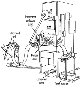
Automatic feed. Automatic feeds reduce the operator exposure during the work process, and often do not require any effort by the operator after the machine is set up and running. The power press in figure 28 has an automatic feeding mechanism with a transparent fixed enclosure guard at the danger area.
Figure 28. Power press with automatic feed
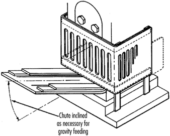
Semi-automatic feed. With semi-automatic feeding, as in the case of a power press, the operator uses a mechanism to place the piece being processed under the ram at each stroke. The operator does not need to reach into the danger area, and the danger area is completely enclosed. Figure 29 shows a chute feed into which each piece is placed by hand. Using a chute feed on an inclined press not only helps centre the piece as it slides into the die, but may also simplify the problem of ejection.
Figure 29. Power press with chute feed
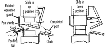
Automatic ejection. Automatic ejection may employ either air pressure or a mechanical apparatus to remove the completed part from a press, and may be interlocked with the operating controls to prevent operation until part ejection is completed. The pan shuttle mechanism shown in figure 30 moves under the finished part as the slide moves toward the up position. The shuttle then catches the part stripped from the slide by the knockout pins and deflects it into a chute. When the ram moves down toward the next blank, the pan shuttle moves away from the die area.
Figure 30. Shuttle ejection system
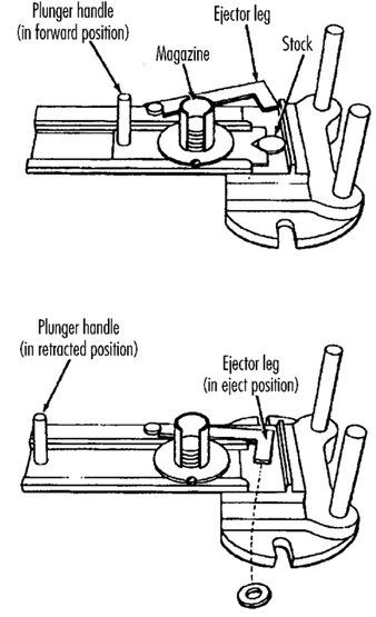
Semi-automatic ejection. Figure 31 shows a semi-automatic ejection mechanism used on a power press. When the plunger is withdrawn from the die area, the ejector leg, which is mechanically coupled to the plunger, kicks the completed work out.
Figure 31. Semi-automatic ejection mechanism
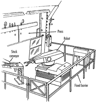
Robots. Robots are complex devices that load and unload stock, assemble parts, transfer objects or perform work otherwise done by an operator, thereby eliminating operator exposure to hazards. They are best used in high-production processes requiring repeated routines, where they can guard against other hazards to employees. Robots may create hazards, and appropriate guards must be used. Figure 32 shows an example of a robot feeding a press.
Figure 32. Using barrier guards to protect robot envelope
Miscellaneous safeguarding aids
Although miscellaneous safeguarding aids do not give complete protection from machine hazards, they may provide operators with an extra margin of safety. Sound judgement is needed in their application and use.
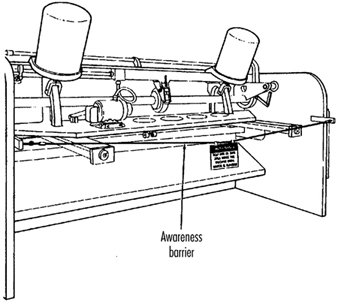
Awareness barriers. Awareness barriers do not provide physical protection, but serve only to remind operators that they are approaching the danger area. Generally, awareness barriers are not considered adequate when continual exposure to the hazard exists. Figure 33 shows a rope used as an awareness barrier on the rear of a power squaring shear. Barriers do not physically prevent persons from entering danger areas, but only provide awareness of the hazard.
Figure 33. Rear view of power shearing square
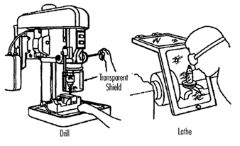
Shields. Shields may be used to provide protection from flying particles, splashing metal-working fluids or coolants. Figure 34 shows two potential applications.
Figure 34. Applications of shields
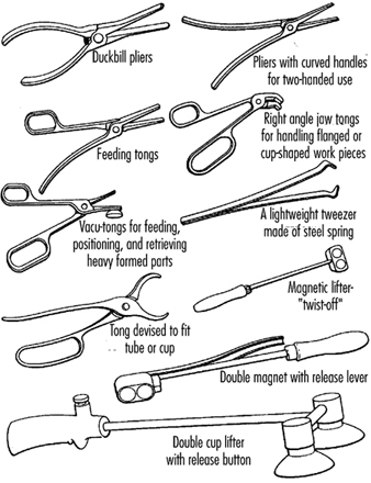
Holding tools. Holding tools place and remove stock. A typical use would be for reaching into the danger area of a press or press brake. Figure 35 shows an assortment of tools for this purpose. Holding tools should not be used instead of other machine safeguards; they are merely a supplement to the protection that other guards provide.
Figure 35. Holding tools
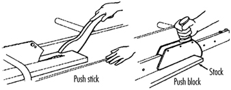
Push sticks or blocks, such as shown in figure 36, may be used when feeding stock into a machine, such as a saw blade. When it becomes necessary for hands to be in close proximity to the blade, the push stick or block may provide a margin of safety and prevent injury.
Figure 36. Use of push stick or push block
Hand and Portable Power Tool Safety
Tools are such a common part of our lives that it is sometimes difficult to remember that they may pose hazards. All tools are manufactured with safety in mind, but occasionally an accident may occur before tool-related hazards are recognized. Workers must learn to recognize the hazards associated with the different types of tools and the safety precautions required to prevent those hazards. Appropriate personal protective equipment, such as safety goggles or gloves, should be worn for protection from potential hazards that may be encountered while using portable power tools and hand tools.
Hand Tools
Hand tools are non-powered and include everything from axes to wrenches. The greatest hazards posed by hand tools result from misuse, use of the wrong tool for the job, and improper maintenance. Some of the hazards associated with the use of hand tools include but are not limited to the following:
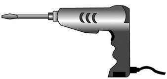
- Using a screwdriver as a chisel may cause the tip of the screwdriver to break off and fly, hitting the user or other employees.
- If a wooden handle on a tool such as a hammer or an axe is loose, splintered or cracked, the head of the tool may fly off and strike the user or another worker.
- A wrench must not be used if its jaws are sprung, because it might slip.
- Impact tools such as chisels, wedges or drift pins are unsafe if they have mushroomed heads which might shatter on impact, sending sharp fragments flying.
The employer is responsible for the safe condition of tools and equipment provided to employees, but the employees have the responsibility to use and maintain the tools properly. Workers should direct saw blades, knives or other tools away from aisle areas and other employees working in close proximity. Knives and scissors must be kept sharp, as dull tools can be more hazardous than sharp ones. (See figure 1.)
Figure 1. A screwdriver

Safety requires that floors be kept as clean and dry as possible to prevent accidental slips when working with or around dangerous hand tools. Although sparks produced by iron and steel hand tools are not normally hot enough to be sources of ignition, when working with or around flammable materials, spark-resistant tools made from brass, plastic, aluminium or wood may be used to prevent spark formation.
Power Tools
Power tools are hazardous when improperly used. There are several types of power tools, usually categorized according to the power source (electric, pneumatic, liquid fuel, hydraulic, steam and explosive powder actuated). Employees should be qualified or trained in the use of all power tools used in their work. They should understand the potential hazards associated with the use of power tools, and observe the following general safety precautions to prevent those hazards from occurring:
- Never carry a tool by the cord or hose.
- Never yank the cord or the hose to disconnect it from the receptacle.
- Keep cords and hoses away from heat, oil and sharp edges.
- Disconnect tools when they are not in use, before servicing, and when changing accessories such as blades, bits and cutters.
- All observers should stay a safe distance away from the work area.
- Secure work with clamps or a vise, freeing both hands to operate the tool.
- Avoid accidental starting. The worker should not hold a finger on the switch button while carrying a plugged-in tool. Tools which have lock-on controls should be disengaged when power is interrupted so that they do not start up automatically upon restoration of power.
- Tools should be maintained with care and kept sharp and clean for best performance. Instructions in the user’s manual should be followed for lubrication and changing accessories.
- Workers should assure they have good footing and balance when using power tools. Appropriate apparel should be worn, as loose clothing, ties or jewellery can become caught in moving parts.
- All portable electric tools that are damaged shall be removed from use and tagged “Do Not Use” to prevent electrical shock.
Protective Guards
Hazardous moving parts of power tools need to be safeguarded. For example, belts, gears, shafts, pulleys, sprockets, spindles, drums, flywheels, chains or other reciprocating, rotating or moving parts of equipment must be guarded if such parts are exposed to contact by workers. Where necessary, guards should be provided to protect the operator and others with respect to hazards associated with:
- the point of operation
- in-running nip points
- rotating and reciprocating parts
- flying chips and sparks, and mist or spray from metal-working fluids.
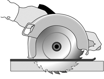
Safety guards must never be removed when a tool is being used. For example, portable circular saws must be equipped with guards. An upper guard must cover the entire blade of the saw. A retractable lower guard must cover the teeth of the saw, except when it makes contact with the work material. The lower guard must automatically return to the covering position when the tool is withdrawn from the work. Note the blade guards in the illustration of a power saw (figure 2).
Figure 2. A circular saw with guard
Safety Switches and Controls
The following are examples of hand-held power tools which must be equipped with a momentary contact “on-off” control switch:
- drills, tappers and fastener drivers
- horizontal, vertical and angle grinders with wheels larger than 2 inches (5.1 cm) in diameter
- disc and belt sanders
- reciprocating and sabre saws.
These tools also may be equipped with a lock-on control, provided that turnoff can be accomplished by a single motion of the same finger or fingers that turn it on.
The following hand-held power tools may be equipped with only a positive “on-off” control switch:
- platen sanders
- disc sanders with discs 2 inches (5.1 cm) or less in diameter
- grinders with wheels 2 inches (5.1 cm) or less in diameter
- routers and planers
- laminate trimmers, nibblers and shears
- scroll saws and jigsaws with blade shanks ¼ inch (0.64 cm) wide or less.
Other hand-held power tools which must be equipped with a constant pressure switch that will shut off the power when the pressure is released include:
- circular saws having a blade diameter greater than 2 inches (5.1 cm)
- chain-saws
- percussion tools without positive accessory-holding means.
Electric Tools
Workers using electric tools must be aware of several dangers. The most serious of these is the possibility of electrocution, followed by burns and slight shocks. Under certain conditions, even a small amount of current can result in fibrillation of the heart which may result in death. A shock also may cause a worker to fall off a ladder or other elevated work surfaces.
To reduce the potential of injury to workers from shock, tools must be protected by at least one of the following means:
- Grounded by a three-wire cord (with a ground wire). Three-wire cords contain two current-carrying conductors and a grounding conductor. One end of the grounding conductor connects to the tool’s metal housing. The other end is grounded through a prong on the plug. Any time an adapter is used to accommodate a two-hole receptacle, the adapter wire must be attached to a known ground. The third prong should never be removed from the plug. (See figure 3.)
- Double insulated. The worker and the tools are protected in two ways: (1) by normal insulation on the wires inside, and (2) by a housing that cannot conduct electricity to the operator in the event of a malfunction.
- Powered by a low-voltage isolation transformer.
- Connected through ground fault circuit interrupters. These are permanent and portable devices which instantaneously disconnect a circuit when it seeks ground through a worker’s body or through grounded objects.
These general safety practices should be followed in using electric tools:
- Electric tools should be operated within their design limitations.
- Gloves and safety footwear are recommended during use of electric tools.
- When not in use, tools should be stored in a dry place.
- Tools should not be used if wires or connectors are frayed, bent or damaged.
- Electric tools should not be used in damp or wet locations.
- Work areas should be well lighted.
Powered Abrasive Wheels
Powered abrasive grinding, cutting, polishing and wire buffing wheels create special safety problems because the wheels may disintegrate and throw off flying fragments.
Before abrasive wheels are mounted, they should be inspected closely and sound (or ring) tested by tapping gently with a light non-metallic instrument to be sure that they are free from cracks or defects. If wheels are cracked or sound dead, they could fly apart in operation and must not be used. A sound and undamaged wheel will give a clear metallic tone or “ring”.
To prevent the wheel from cracking, the user should be sure it fits freely on the spindle. The spindle nut must be tightened enough to hold the wheel in place without distorting the flange. Follow the manufacturer’s recommendations. Care must be taken to assure that the spindle wheel will not exceed the abrasive wheel specifications. Due to the possibility of a wheel disintegrating (exploding) during start-up, the worker should never stand directly in front of the wheel as it accelerates to full operating speed. Portable grinding tools need to be equipped with safety guards to protect workers not only from the moving wheel surface, but also from flying fragments in case of breakage. In addition, when using a powered grinder, these precautions should be observed:
- Always use eye protection.
- Turn off the power when tool is not in use.
- Never clamp a hand-held grinder in a vise.
Pneumatic Tools
Pneumatic tools are powered by compressed air and include chippers, drills, hammers and sanders. Although there are several potential dangers encountered in the use of pneumatic tools, the main one is the danger of getting hit by one of the tool’s attachments or by some kind of fastener the worker is using with the tool. Eye protection is required and face protection is recommended when working with pneumatic tools. Noise is another hazard. Working with noisy tools such as jackhammers requires proper, effective use of appropriate hearing protection.
When using a pneumatic tool, the worker must check to assure that it is fastened securely to the hose to prevent a disconnection. A short wire or positive locking device attaching the air hose to the tool will serve as an added safeguard. If an air hose is more than½ inch (1.27 cm) in diameter, a safety excess flow valve should be installed at the source of the air supply to shut off the air automatically in case the hose breaks. In general, the same precautions should be taken with an air hose that are recommended for electric cords, because the hose is subject to the same kind of damage or accidental striking, and it also presents a tripping hazard.
Compressed-air guns should never be pointed toward anyone. Workers should never “dead-end” the nozzle against themselves or anyone else. A safety clip or retainer should be installed to prevent attachments, such as a chisel on a chipping hammer, from being unintentionally shot from the barrel. Screens should be set up to protect nearby workers from being struck by flying fragments around chippers, riveting guns, air hammers, staplers or air drills.
Airless spray guns that atomize paints and fluids at high pressures (1,000 pounds or more per square inch) must be equipped with automatic or manual visual safety devices that will prevent activation until the safety device is manually released. Heavy jackhammers can cause fatigue and strains which may be reduced by the use of heavy rubber grips that provide a secure handhold. A worker operating a jackhammer must wear safety glasses and safety shoes to protect against injury if the hammer slips or falls. A face shield also should be used.
Fuel-Powered Tools
Fuel-powered tools are usually operated using small gasoline-powered internal combustion motors. The most serious potential dangers associated with the use of fuel-powered tools comes from hazardous fuel vapours that can burn or explode and give off dangerous exhaust fumes. The worker must be careful to handle, transport and store the gasoline or fuel only in approved flammable liquid containers, according to proper procedures for flammable liquids. Before the tank for a fuel-powered tool is refilled, the user must shut down the engine and allow it to cool to prevent accidental ignition of hazardous vapours. If a fuel-powered tool is used inside a closed area, effective ventilation and/or protective equipment is necessary to prevent exposure to carbon monoxide. Fire extinguishers must be available in the area.
Explosive Powder-Actuated Tools
Explosive powder-actuated tools operate like a loaded gun and should be treated with the same respect and precautions. In fact, they are so dangerous that they must be operated only by specially trained or qualified employees. Suitable ear, eye and face protection are essential when using a powder-actuated tool. All powder-actuated tools should be designed for varying powder charges so that the user can select a powder level necessary to do the work without excessive force.
The muzzle end of the tool should have a protective shield or guard centred perpendicularly on the barrel to protect the user from any flying fragments or particles that might create a hazard when the tool is fired. The tool must be designed so that it will not fire unless it has this kind of safety device. To prevent the tool from firing accidentally, two separate motions are required for firing: one to bring the tool into position, and another to pull the trigger. The tools must not be able to operate until they are pressed against the work surface with a force at least 5 pounds greater than the total weight of the tool.
If a powder-actuated tool misfires, the user should wait at least 30 seconds before trying to fire it again. If it still will not fire, the user should wait at least another 30 seconds so that the faulty cartridge is less likely to explode, then carefully remove the load. The bad cartridge should be put in water or otherwise safely disposed of in accordance with employer’s procedures.
If a powder-actuated tool develops a defect during use, it should be tagged and taken out of service immediately until it is properly repaired. Precautions for the safe use and handling of powder-actuated tools include the following:
- Powder-actuated tools should not be used in explosive or flammable atmospheres except upon issuance of a hot-work permit by an authorized person.
- Before using the tool, the worker should inspect it to determine that it is clean, that all moving parts operate freely and that the barrel is free from obstructions.
- The tool should never be pointed at anybody.
- The tool should not be loaded unless it is to be used immediately. A loaded tool should not be left unattended, especially where it may be available to unauthorized persons.
- Hands should be kept clear of the barrel end.
In using powder-actuated tools to apply fasteners, the following safety precautions should be considered:
- Do not fire fasteners into material that would let them pass through to the other side.
- Do not drive fasteners into materials like brick or concrete any closer than 3 inches (7.6 cm) to an edge or corner, or into steel any closer than ½ inch (1.27 cm) to a corner or edge.
- Do not drive fasteners into very hard or brittle material that might chip, shatter or make the fasteners ricochet.
- Use an alignment guide when shooting fasteners into existing holes. Do not drive fasteners into a spalled area caused by an unsatisfactory fastening.
Hydraulic Power Tools
The fluid used in hydraulic power tools must be approved for the expected use and must retain its operating characteristics at the most extreme temperatures to which it will be exposed. The manufacturer’s recommended safe operating pressure for hoses, valves, pipes, filters and other fittings must not be exceeded. Where there is a potential for a leak under high pressure in an area where sources of ignition, such as open flames or hot surfaces, may be present, the use of fire-resistant fluids as the hydraulic medium should be considered.
Jacks
All jacks—lever and ratchet jacks, screw jacks and hydraulic jacks—must have a device that stops them from jacking up too high. The manufacturer’s load limit must be permanently marked in a prominent place on the jack and should not be exceeded. Use wooden blocking under the base if necessary to make the jack level and secure. If the lift surface is metal, place a 1-inch-thick (2.54 cm) hardwood block or equivalent between the underside of the surface and the metal jack head to reduce the danger of slippage. A jack should never be used to support a lifted load. Once the load has been lifted, it should immediately be supported by blocks.
To set up a jack, make certain of the following conditions:
- The base rests on a firm level surface.
- The jack is correctly centred.
- The jack head bears against a level surface.
- The lift force is applied evenly.
Proper maintenance of jacks is essential for safety. All jacks must be inspected before each use and lubricated regularly. If a jack is subjected to an abnormal load or shock, it should be thoroughly examined to make sure it has not been damaged. Hydraulic jacks exposed to freezing temperatures must be filled with an adequate antifreeze liquid.
Summary
Workers who use hand and power tools and who are exposed to the hazards of falling, flying, abrasive and splashing objects and materials, or to hazards of harmful dusts, fumes, mists, vapours or gases, must be provided with the appropriate personal equipment necessary to protect them from the hazard. All hazards involved in the use of power tools can be prevented by workers following five basic safety rules:
- Keep all tools in good condition with regular maintenance.
- Use the right tool for the job.
- Examine each tool for damage before use.
- Operate tools according to the manufacturer’s instructions.
- Select and use appropriate protective equipment.
Employees and employers have a responsibility to work together to maintain established safe work practices. If a an unsafe tool or hazardous situation is encountered, it should be brought to the attention of the proper individual immediately.
" DISCLAIMER: The ILO does not take responsibility for content presented on this web portal that is presented in any language other than English, which is the language used for the initial production and peer-review of original content. Certain statistics have not been updated since the production of the 4th edition of the Encyclopaedia (1998)."