- You are here:
-
Home

- k2 Feed
Wood Planning Machines
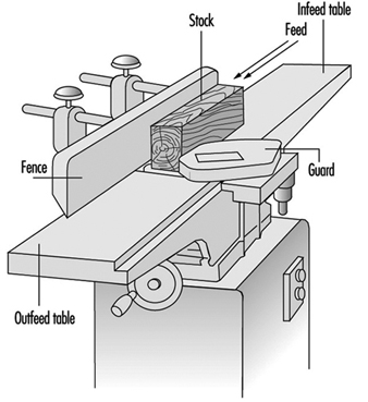
The development of stationary planing machines can be traced back to the beginning of the 19th century. On the first machines of this type, the workpiece was clamped to a carriage and fed below a horizontal shaft fitted with blades extending over the full working width. In 1850 a planing machine was built in Germany on which the workpiece was fed over a cutterblock located between two tables used to position and to support the workpiece. Apart from technical improvements this basic design has been maintained to this day. Such a machine is called a surface planing machine or a jointer (see figure 1).
Figure 1. Jointer
More recently, machines were designed to plane the upper surface of a workpiece to a predetermined thickness by means of a horizontally rotating cutterblock. The distance between the cutting circle diameter and the surface of the table supporting the workpiece is adjustable. Such machines are called one-side-thickness planing machines.
These two basic machine types were eventually combined into a machine which could be used for both surface and thickness planing. This development ended in planing machines for two-, three- and four-sided working in one pass.
From the point of view of occupational safety and health, it is strongly recommended that measures be taken for the extraction of wood dust and chips from the planing machine (e.g., by connecting the planing machine to a dust extraction system). Dust originating from hardwood (oak, beech) and tropical wood is considered a particular health hazard and must be extracted. Measures to reduce the noise level of planing machines should also be taken. An automatic brake for the cutterblock is compulsory in many countries.
Surface Planing Machines
A surface planing machine has rigid main frame that supports the infeed and the outfeed table. The cutterblock is located between the two tables and mounted on ball bearings. The main frame should be ergonomically designed (i.e., it should enable the operator to work comfortably).
Hand-operated control devices should be installed in such a way that the operator is not placed in a hazardous situation when operating them, and the possibility of inadvertent operation should be minimized.
The side of the main frame facing the operator’s position must be free of projecting parts such as handwheels, levers and so on. The table to the left of the cutterblock (outfeed table) is normally set at the same height as the cutting circle of the cutterblock. The table to the right of the cutterblock (infeed table) is set lower than the outfeed table to obtain the desired depth of cut. Contact between the table lips and the cutterblock should not be possible over the full setting range of the tables. However, the clearance between the table lips and the cutting circle of the cutterblock shall be as small as possible to provide for good support of the workpiece to be planed.
The major operations on a surface planing machine are flatting and edging. The position of the hands on the workpiece is important from an operational and safety viewpoint. When flatting, the workpiece should be fed with one hand, with the other hand holding it down initially on the infeed table. As soon as there is a sufficient portion of timber on the outfeed table, the latter hand can pass safely over the bridge-guard to apply pressure on the outfeed table and will be followed by the feeding hand to complete the feeding operation. When edging, the hands should not pass over the cutterblock while in contact with the timber. Their prime function is to exert horizontal pressure on the workpiece to maintain it square to the fence.
The noise produced by the rotating cutterblock often may exceed the level considered harmful to the ear. Measures to reduce the noise level are therefore necessary. Some of the noise reduction measures which have proved successful on surface planers are the following:
- use of a “quiet” cutterblock (e.g., a round form with minimum blade projection, helical blade instead of straight blade, segmental rotating tools with offset cutting)
- slotted or drilled table lips (the configuration and the dimensions of the apertures in the table lips must be selected so that no accident hazards arise; e.g., slots shall be no more than 6 mm wide and the diameter of the holes shall not exceed 6 mm)
- aerodynamic design of the chip deflectors below the table lips
- reduction of the cutterblock speed to below 1,000 rpm, provided the surface quality of the workpiece is still satisfactory.
Noise reduction up to 12 dBA when idling and 10 dBA under load can be achieved.
Cutterblocks should have a circular cross-section, and the chip clearance grooves and slots should be as small as possible. The blades and inserts shall be properly secured, preferably by form lock fixing.
The cutterblock rotates generally at speeds between 4,500 and 6,000 rpm. The diameters of conventional cutterblocks vary from 56 to 160 mm, and their lengths (working widths) from 200 to 900 mm. By analogy with the kinematics of conventional milling, the surface of the workpiece planed with a cutterblock is composed of cycloid arcs. The surface quality of the work therefore depends on the speed and diameter of the cutterblock, the number of cutting blades and the feed rate of the workpiece.
Equipping surface planing machines with an automatic brake for the cutterblock is recommended. The brake should be activated when the machine is stopped, and the braking time should not exceed 10 seconds.
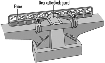
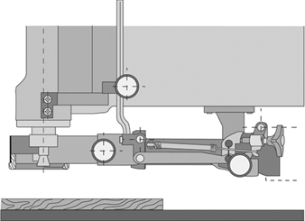
Access to the cutterblock at the rear of the fence should be prevented by a guard attached either to the fence or the fence support. The cutterblock in front of the fence should be guarded by an adjustable bridge-type guard fixed to the machine (e.g., to the main frame on the outfeed table side) (see figure 2). Access to the transmission elements should be prevented by a fixed guard.
Figure 2. Fence & rear cutterblock guard
Hazards
As the cutterblock rotates opposite to the direction in which the workpiece is fed, the hazard of kickback exists. If the workpiece is ejected, the operator’s hand or fingers may come in contact with the rotating cutterblock unless adequate guarding has been provided. It also frequently happens that the hand comes in contact with the cutterblock while feeding the workpiece with stretched fingers instead of pushing it forward with closed fist. Cutting blades not properly secured may be ejected by centrifugal force and may cause severe injury and/or material damage.
Guarding systems for surface planing machines
In many countries legislation covering the use of surface planing machines requires that the cutterblock be covered by an adjustable guarding system in order to prevent accidental contact of the operator’s hand with the rotating cutterblock.
In 1938, the SUVA introduced a planer guard which efficiently met all practical requirements. Over the years this guard has proved useful not only as a guarding system but also as an aid for most operations. It is well accepted by the woodworking trade in Switzerland, and almost all industrial surface planing machines are equipped with it. The design features of this guard have been introduced into the draft European standard for surface planing machines. The main features of this guard are the following:
- strong and rigid
- not easily deflected to expose cutterblock
- always stays parallel to the cutterblock axis regardless of its horizontal or vertical adjustment
- easily adjustable horizontally and vertically without the use of a tool.
However, accidents still happen. These accidents are mainly caused by failure to adjust the guard properly. Therefore, SUVA engineers have developed a bridge-type guard which covers the cutterblock in front of the fence automatically, and constantly exerts a defined pressure against the workpiece or the fence. This guard has been available since 1992.
The main design features of this new guard, called “Suvamatic”, are the following:
- complete guarding of the cutterblock. The full planing width is safeguarded by one single bridge-type guard. It can be folded down using a hinged locking system. This prevents the guard from projecting too far over the face of the machine.
- practical workpiece guiding system. The workpiece guiding system consists of a pressure pad and a guide for the workpiece. Both are fitted to the tip of the guard. The latter can be tilted to guide the workpiece both for flatting and edging.
- pressure application to assist work. For edging, the guard exerts pressure in direction of the fence. After edging, it automatically covers the full length of the cutterblock in front of the fence.
- automatic lifting and lowering of the guard. For flatting, the guard is lifted by the workpiece guide. After flatting, it lowers itself automatically to cover the cutterblock.
- guard can be locked in position for batch jobs. For batch jobs, the guard can be locked in vertical position to just accommodate the thickness of the workpiece. The guard will return automatically to this preset position after being pressed down.
- will fit all machines. The guard can be fitted to all surface planing machines and combined surface and thickness planing machines.
One-Side Thickness Planing Machines
The main frame of a one-side thickness planing machine houses the cutterblock, thickness planing table and feed elements.
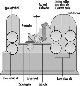
Once the workpiece has been flattened and edged on a surface planing machine, it is planed to the desired thickness on the thickness planing machine. Unlike that of a surface planing machine, the cutterblock of a thickness planing machine is located above the planing table and the workpiece is no longer fed by hand but mechanically by feed rollers. The feed rollers are driven either by a separate motor (approximately 1 kW) or via a speed-reduction gearbox receiving its power from the cutterblock motor. With a separate drive the feed rate remains constant, but if the power is transmitted from the cutterblock motor the feed rate varies according to the cutterblock speed. Feed rates between 4 and 35 m/min are common.
Two spring-mounted feed rollers rest on the upper surface of the workpiece. The feed roller in front of the cutterblock is grooved for better grip on the workpiece; the feed roller at the outfeed end of the cutterblock is smooth. An infeed and an outfeed pressure bar located next to the cutterblock press the workpiece down onto the table, thereby ensuring a clean and even cut. The design and arrangement of the feed rollers and pressure bars should be such that contact with the rotating cutterblock is impossible.
Sectional feed rollers and pressure bars allow for the simultaneous working of two or more workpieces of slightly different thickness. From the point of view of accident prevention, sectional feed rollers and pressure bars are essential. The width of the individual feed roller or pressure bar section should not exceed 50 mm.
Two idle rollers are arranged in the table. They are designed to facilitate the passage of the workpiece over the table.
The surface of the table must be a plane free from slots or holes. Accidents involving an operator’s fingers being squeezed between openings and the workpiece have occurred. Vertical adjustment of the table may be manual or power assisted. A mechanical end-stop should prevent any contact of the table with the cutterblock or feed rollers. It must be ensured that the vertical adjustment mechanism hold the table in a stable position.
In order to prevent the feeding of oversize workpieces, a device (e.g., a fixed rod or fixed bar) is located on the infeed side of the machine, thereby limiting the maximum workpiece height. A maximum height of 250 mm between the surface of the table in its lowest position and the above-mentioned safety device is rarely exceeded. The usual working width varies between 315 and 800 mm (for special machines this width might go up to 1,300 mm).
The cutterblock diameter generally varies from 80 to 160 mm. Normally four blades are fitted to the cutterblock. The cutterblock rotates at speeds between 4,000 and 6,000 rpm, and its input power varies from 4 to 20 kW. The maximum depth of cut is 10 to 12 mm.
To minimize the danger of kickback, one-side thickness planing machines should be fitted with an anti-kickback device covering the full working width of the machine. This anti-kickback device generally consists of several grooved elements arranged on a rod. The individual element is between 8 and 15 mm wide, and it falls under its own weight to the rest position. The lowest point of the individual grooved element in its rest position should be 3 mm below the cutting circle of the cutterblock. The grooved elements should be made of a material (preferably steel) with a resilience strength of 15 J/cm2 and a surface hardness of 100 HB.
The following noise-reduction measures have proved to be successful on one-side thickness planing machines:
- use of a “quiet” cutterblock (like that suggested for surface planing machines)
- aerodynamic design of the pressure bars and the chip extraction hood
- reduction of the cutterblock speed
- partial or complete enclosure of the machine (tunnel-like design of the infeed and outfeed opening with sound-absorbing material on the surface facing the source of noise)
Noise reduction of up to 20 dBA may be achieved by a well designed complete enclosure.
Hazards
The major cause of accidents on one-side thickness planing machines is kickback of the workpiece. Kickback may happen because of:
- poor maintenance of the anti-kickback device (the individual elements may not fall free under their own weight but stick together because of dust accumulation; the grooves in the elements may be covered with resin, be blunt or be incorrectly reground)
- poor maintenance of the sectional feed rollers and pressure bars (e.g., resin-covered or rusty sections)
- insufficient spring load on feed rollers and pressure bars when several pieces of non-uniform thickness are fed at the same time.
Typical causes of other accidents are:
- contact of the hand with the rotating cutterblock when removing chips and dust from the table by hand rather than with a wooden stick or rake
- ejection of cutterblock blades due to incorrect fixing.
Combined Surface Planing and Thicknessing Machines
The design and operation of combined machines (see figure 3) are similar to those of the individual machines described above. The same can be said in regards to the feed rates, motor power, table and roller adjustments. For thickness planing the surface planing tables are either pulled away, folded down or lifted up sideways, exposing the cutterblock, which is covered by a chip extraction hood to prevent access Combined machines are mainly used in small workshops with few workers, or where space is limited (i.e., in cases where the installation of two individual machines is impossible or unprofitable).
Figure 3. Combined surface & thickness planer
The changeover from one operation to the other is often time-consuming and may be annoying if only a few pieces have to be machined. Moreover, usually only one person at a time can use the machine. However, since 1992 machines have been introduced to the market where simultaneous operation (surface and thickness planing at the same time) is possible.
The hazards of combined machines are to a large extent identical to the hazards listed for the individual machines.
Routing Machines
Stationary routing machines are used in general for the manufacture of wood articles and furniture elements, but sometimes also for machining plastics and light alloys. Important types of routing machines are copy routers, pattern millers, machines with mobile router heads and automatic copying machines. The automatic copying machines are generally used for machining several workpieces simultaneously.
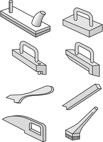
A common feature of all routing machines is that the tool is located above the workpiece support, which is normally a table. The tool-spindle axis is nearly always vertical, but on some machines the router head, and thus also the tool-spindle axis, may be tilted. The machining head is lowered for machining and returns automatically to its initial (rest) position. On older machines the machining head is lowered manually by operating a mechanical foot-pedal or hand lever. On modern machines the head is generally lowered by a pneumatic or hydraulic system. Figure 1 shows various accessories (hold-down shoes, guides and so on) and the Swiss National Accident Insurance Organization (SUVA) safety guard.
Figure 1. SUVA safety device with routing tool in working position
The tool-spindle is driven either by a belt drive or directly by a high-frequency motor, which is often of the two-speed type. The tool-spindle speeds generally range from 6,000 to 24,000 rpm. They are lower in pattern millers, where the lowest speed may be 250 rpm. Pattern millers are often equipped with a gearbox for the selection of different speeds.
The cutting diameter of the routing tool varies from 3 to 50 mm. However, on special pattern millers the cutting diameter of the tool may be as large as 300 mm.
Tooling
On routing machines single-edged spoon bits, double-edged panel cutters or solid-shaped cutters mainly are used. Like any tool they must be designed and made of such materials that will withstand the forces and loads to be expected during operation. Machines should be used and maintained in compliance with the manufacturer’s instructions.
The routing tools should be:
- clearly and permanently marked with the permissible speed, e.g., less than 20,000 rpm
- of a type tested by an approved body
- of round form design with a minimal radial cutting edge projection to reduce the danger of kickback.
Guarding of the tool
On routing machines where the tool is moving and the workpiece remains fixed, access to the rotating tool should be prevented by an adjustable guard (hand protector). It should be supplemented by a movable guard which can be lowered on to the workpiece surface. The lower end of this movable guard may be a brush.
On routing machines where the workpiece is held and/or fed by hand, it is highly recommended to use a safety device exerting vertical pressure on the workpiece. The SUVA has designed such a guard. This safety device has been successfully used since the end of the 1940s and is still the most complete guard of its kind. Its main features are:
- prevention of unintentional contact with the rotating tool both in its rest position and in its working position
- fast and easy changeover from one size of hold-down shoe to another. Several sizes of hold-down shoes are available to fit tools with different cutting diameters
- manually adjustable amount of pressure exerted on the workpiece by the hold-down shoe
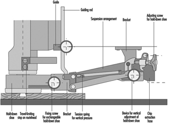
- automatic return of the hold-down shoe to its upper position when the router head rises to its rest position. The guarding device can be adjusted so that the hold-down shoe may be lifted only when the lower edge of the tool is above the level of the lower edge of the hold-down shoe; this is to prevent any unintentional contact with the tool from below (see figure 2. Serious injuries to the back of the hand, where the tendons are protected only by the skin, are thus avoided.
Figure 2. Safety device with routing tool in initial position
- possibility of connection of a chip extraction system to the guarding device.
This guarding device also enables workpieces to be routed along a guide with the aid of a horizontal pressure pad.
Hazards
Routing machines have been found to be less dangerous than vertical spindle moulding machines. One reason for this is the smaller diameter of most routing tools. However, the tools on routing machines are easily accessible and thus present a constant hazard for the hands and arms of the operator. Therefore, copy routers, where the workpiece is generally fed by hand, are by far the most dangerous routing machines.
Causes of accidents
The main causes of router accidents are:
- unintentional contact of the hand or arm with the rotating tool in its rest position (1) when removing chips and dust from the table by hand rather than using a wooden stick, (2) when the workpiece or the jig is not correctly handled or (3) when the sleeve of the operator’s clothing becomes entangled in the rotating tool
- unintentional contact of the hand with the routing tool as a result of kickback of the workpiece held by hand.
Kickback may happen because of:
- an unsafe working practice
- faults in the workpiece (knots, etc.)
- workpieces being fed into the tool too abruptly or from the wrong direction
- blunt cutter edges
- inadequate cutting speed
- incorrect fixing of the workpiece to the jig
- workpiece breakage
- ejection of the tool or parts of the tool due to bad tool design, excessive hardness of the tool material, faults in the material of the tool, overspeed of the tool or poor clamping of the tool in the tool holder.
In the event of ejection of a tool or workpiece, not only the operator but also other persons working in the area may be injured by ejected parts.
Measures to prevent accidents
Measures to prevent accidents should be directed at:
- the design and construction of the machine
- the tooling
- guarding the tool in its rest position (figure 15) and as far as possible in the working position (figure 14), in particular when the workpiece is held and fed by hand.
Design and Construction of the Machine
Routing machines must be designed to be safe to operate. It should be ensured that:
- the machine is sufficiently rigid
- the electrical equipment conforms to safety regulations
- actuators used to initiate a start function or movement of a machine element are constructed and mounted so as to minimize inadvertent operation
- access to moving machine parts, such as belt drives, hydraulic or pneumatically moved router heads or travelling tables on machines with automatic feeds, are prevented by adequate guarding
- the actual revolutions per minute of the tool are clearly visible to the operator
- the safety devices and chip extraction systems are easy to install
- the noise level of the machine is reduced as far as possible.
Furthermore, it is advisable to equip the tool drive of the routing machine with an automatic brake that activates when the machine is stopped. The braking time should not exceed 10 seconds.
Sample checklist
Housekeeping
1. A daily housekeeping programme is essential.
2. Dust accumulations of 1/8” depth in any area indicate a need for cleaning. It should be noted that any accumulation of dust may lead to a fire. The finer the dust, the greater the hazards.
3. Clean wood dust frequently.
a. Wipe down daily around hot surfaces.
b. Major blow down or vacuum when possible of all areas, including rafters, at least twice per year.
c. When concentrations are high, work small areas at a time.
d. Low humidity increases the potential for hazards and should be taken in consideration during blow downs.
4. Schedule blow downs or clean ups while equipment is down, such as Friday afternoons and weekends.
Electrical maintenance
1. Inspect/clean all motors regularly to avoid dust build-up.
2. Ensure all electrical boxes and panels meet the National Electrical Code requirements for their classified location.
3. Listen for unusual sounds, note unusual smells and watch for visual dust accumulations on machines and motors. Check motors and other electricals often to detect overheating.
4. Ensure that maintenance or operating personnel are lubricating bearings to motors, conveyors, chains and sprockets on a timely basis.
5. Ensure that electrical panels and boxes are kept closed and maintained to prevent dust accumulations, including keeping all knockout holes plugged.
Fire prevention
1. Actively prohibit smoking in unauthorized locations.
2. Adopt procedures for hot-work permits and ensure that procedures are followed.
3. Do not allow operator-controlled machines to operate unattended.
4. Install a device at the mouth of the dust collecting system to prevent sanding belts and other spark producing items from entering the system and causing a fire.
5. Trap metal in wood hogs by installing magnets in the conveyor system and metal detectors in the hog. Policies and procedures should be implemented to prevent metal and other foreign objects from reaching the hogs.
6. Conduct weekly and monthly inspections of fire protective systems including fire extinguishers, fire hoses, alarms and sprinkler control valves.
7. Ensure that boiler rooms and heating equipment are free of dust accumulations, that written boiler start-up procedures are being followed and that properly classified equipment is used.
8. Recognize the correct procedure in fighting dust fires.
9. Request a detailed inspection by the local fire marshal or insurance carrier.
10. Encourage mock drills/visits by the local fire department.
11. Install spark detection and extinguishing systems in dust collection systems and check periodically to ensure that they are working.
12. Review evacuation plans, emergency lighting, fire drills periodically for each work shift.
Miscellaneous
1. Contact insurance carrier for assistance in hazard identifications associated with safety, health and fire prevention.
2. Contact appropriate government safety agencies for additional assistance.
3. Employees should enter dust silos only when confined space procedures are followed.
4. All operators should ensure that dust collecting systems are working properly and report any malfunctions to management immediately.
5. Check for objects obstructing the ducts to the dust system.
6. It is recommended that all supervisors, safety committee members and other employees be made aware of the contents of this voluntary checklist to achieve maximum implementation.
Woodworking Processes
For the purposes of this article, the processes of the woodworking industry will be considered to start with the reception of converted timber from the sawmill and continue until the shipping of a finished wood article or product. Earlier stages in the handling of wood are dealt with in the chapters Forestry and Lumber industry.
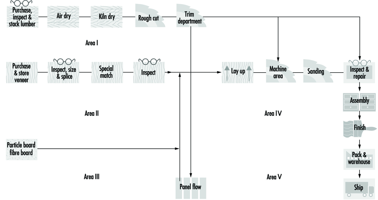
The woodworking industry produces furniture and a variety of building materials, ranging from plywood floors to shingles. This article covers the main stages in the processing of wood for the production of wooden products, which are machine working of natural wood or manufactured panels, assembly of machined parts and surface finishing (e.g., painting, staining, lacquering, veneering and so on). Figure 1 is a flow diagram for wood furniture manufacturing, which covers nearly the whole range of these processes.
Figure 1. Flow diagram for wood furniture manufacturing
Drying. Some furniture manufacturing facilities may purchase dried lumber, but others perform drying onsite using a drying kiln or oven, fired by a boiler. Usually wood waste is the fuel.
Machining. Once the lumber is dried, it is sawed and otherwise machined into the shape of the final furniture part, such as a table leg. In a normal plant, the wood stock moves from rough planer, to cutoff saw, to rip saw, to finish planer, to moulder, to lathe, to table saw, to band saw, to router, to shaper, to drill and mortiser, to carver and then to a variety of sanders.
Wood can be hand carved/worked with a variety of hand tools, including chisels, rasps, files, hand saws, sandpaper and the like.
In many instances, the design of furniture pieces requires bending of certain wooden parts. This occurs after the planing process, and usually involves the application of pressure in conjunction with a softening agent, such as water, and increased atmospheric pressure. After bending into the desired shape, the piece is dried to remove excess moisture.
Assembly. Wood furniture can either be finished and then assembled, or the reverse. Furniture made of irregularly shaped components is usually assembled and then finished.
The assembly process usually involves the use of adhesives (either synthetic or natural) in conjunction with other joining methods, such as nailing, followed by the application of veneers. Purchased veneers are trimmed to correct size and patterns, and bonded to purchased chipboard.
After assembly, the furniture part is examined to ensure a smooth surface for finishing.
Pre-finishing. After initial sanding, an even smoother surface is attained by spraying, sponging or dipping the furniture part with water to cause the wood fibres to swell and “raise”. After the surface has dried, a solution of glue or resin is applied and allowed to dry. The raised fibres are then sanded down to form a smooth surface.
If the wood contains rosin, which can interfere with the effectiveness of certain finishes, it may be derosinated by applying a mixture of acetone and ammonia. The wood is then bleached by spraying, sponging or dipping the wood into a bleaching agent such as hydrogen peroxide.
Surface finishing. Surface finishing may involve the use of a large variety of coatings. These coatings are applied after the product is assembled or in a flat line operation before assembly. Coatings could normally include fillers, stains, glazes, sealers, lacquers, paints, varnishes and other finishes. The coatings may be applied by spray, brush, pad, dip, roller or flow-coating machine.
Coatings can be either solvent based or water based. Paints may contain a wide variety of pigments, depending on the desired colour.
Hazards and Precautions
Machining safety
Woodworking manufacturing has many of the hazards to safety and health that are common to general industry, with a much larger proportion of extremely hazardous equipment and operations than most. Consequently, safety requires constant attention to safe work habits by employees, vigilant supervision, and maintenance of a safe work environment by employers.
Although in many instances woodworking machinery and equipment may be purchased without the necessary guards and other safety devices, it is management’s responsibility to provide adequate safeguards before such machinery and equipment is used. See also the articles “Routing machines” and “Wood planing machines”.
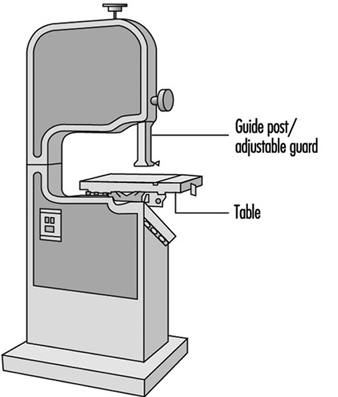
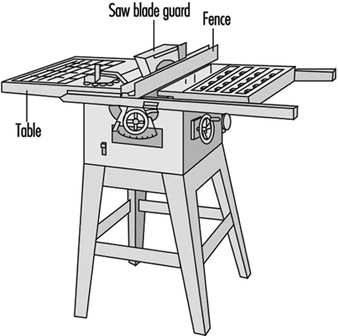
Sawing machines. Employees should be made aware of the safe operating practices necessary for the proper use of various woodworking saws (see figure 2 and figure 3).
Figure 2. Band saw
Specific guidelines are as follows:
1. When feeding a table saw, hands must be kept out of the line of the cut. No guard can prevent a person’s hand from following the stock into the saw. When ripping with the fence gauge near the saw, a push stick or suitable jig must be used to complete the cut. See figure 4.
Figure 4. Push sticks
2. The saw blade must be positioned so as to minimize its protrusion above the stock; the lower the blade, the less chance for kickbacks. It is good practice to stand out of the line of the stock being ripped. A heavy leather apron or other guard for the abdomen is recommended.
3. Freehand sawing is always dangerous. The stock must always be held against a gauge or fence. See figure 3.
4. The saw must be appropriate for the job. For instance, it is an unsafe practice to rip with a table saw not equipped with a non-kickback device. Kickback aprons are recommended.
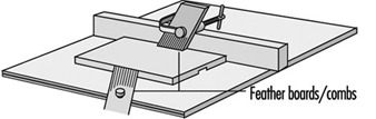
5. The dangerous practice of removing a hood guard because of narrow clearance on the gauge side can be avoided by clamping a filler board to the table between the gauge and the saw and using it to guide the stock. Employees must never be permitted to bypass guards. Combs, featherboards (see figure 5) or suitable jigs must be provided where standard guards cannot be used.
Figure 5. Featherboards & combs
6. Crosscutting long boards on a table saw should be avoided because the operator is required to use considerable hand pressure near the saw blade. Also, boards extending beyond the table may be struck by people or trucks. Long stock should be crosscut on a swing pull saw or radial arm saw with adequate supporting bench.
7. Work that should be done on special power-feed machines should not be done on general-purpose hand-fed machines.
8.To set a gauge of a table saw without taking off the guards, a permanent mark should designate the line of cut on the table top.
9. It is considered safe practice to bring equipment to a complete stop before adjusting blades or fences, and to disconnect the power source when changing blades.
10. A brush or stick should be used to clean sawdust and scrap from a saw.
A table saw is also called a variety saw because it can perform a wide variety of sawing functions. For this reason the operator should have a variety of guards, because no one guard can protect from every function. See figure 3.
Cutting machines. Cutting machines can also be hazardous if not adequately guarded and always used with respect and alertness. Cutting tools should be kept well sharpened and correctly balanced on their spindles.
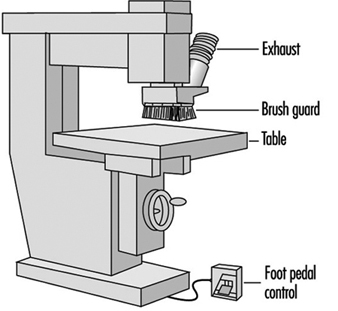
The router shown in figure 6 has a brush guard. Other routers may have a ring guard, a round guard that encircles the router bit. The purpose of guards is to keep the hands away from the cutting bit. Computer numerical controlled (CNC) routers may have several bits and are high production machines. On CNC machines the operator’s hands are kept further from the bit area. However, another problem is the high amount of wood dust. See also the article “Routing machines”.
Figure 6. Router
Guarding on a jointer or surface planing machine is mainly to keep the operator’s hands away from the revolving knives. The “mutton chop”-type guard allows only the portion of the knives which are cutting the stock to be exposed (see figure 7). The exposed portion of the knives behind the fence should also be guarded.
Figure 7. Jointer
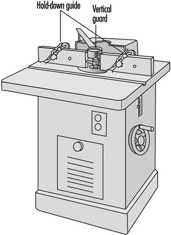
The shaper is a potentially very dangerous machine (see figure 8). If the shaper knives become separated from the above and below collars on the arbor, they can be thrown with great force. Also, stock must often be held close to the knives. This holding must be done with a fixture instead of by the operator’s hands. Featherboards can be used to hold the stock down against the table. Ring or saucer guards should be used whenever possible. A saucer guard is a round, flat, plastic disk that is mounted horizontally on the arbor above the shaper knives.
Figure 8. Shaper
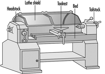
A lathe should be guarded by a hood guard because there is a danger of the stock being thrown from the machine. See figure 9. It is good practice for the hood to be interlocked with the motor so the lathe cannot be run unless the hood guard is in place.
Figure 9. Lathe
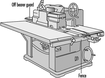
A ripsaw should have anti-kickback fingers installed to prevent the stock from reversing its direction and striking the operator. See figure 10. Also, the operator should wear a padded apron to lessen the impact if a kickback does occur.
Figure 10. Ripsaw
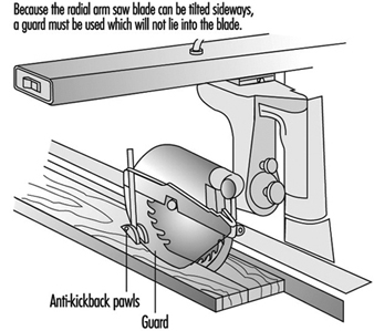
Because the radial arm saw blade can be tilted sideways, a guard must be used which will not lie into the blade. See figure 11.
Figure 11. Radial arm saw
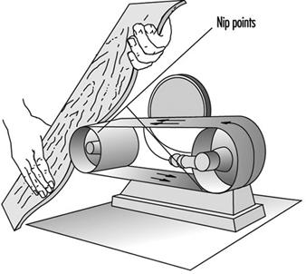
Sanding machines. Machined stock pieces are sanded down using belt, jitterbug, disc, drum or orbital sanders. Nip points are created in sanding belts. See figure 12. Often these nip points can be guarded with a hood which will also be part of a dust exhaust system.
Figure 12. Sander
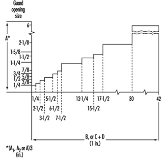
Machine guarding. Figure 13 illustrates that the opening between a guard and the point of contact must be decreased as the distance decreases.
Figure 13. Distance between guard & point of operation
Miscellaneous machine safety concerns. Care must be taken that the use of stock-clamping/holding devices do not create additional hazards.
Most woodworking machines create the necessity of the operator (and helper) wearing eye protection.
It is common practice for employees to blow dust off of themselves with compressed air. They should be cautioned to keep air pressure below 30 psi and to avoid blowing into eyes or open cuts.
Wood dust hazards
Machines that produce wood dust should be equipped with dust-collecting systems. If the exhaust system is inadequate to dispose of the wood dust, the operator may need to wear a dust respirator. The International Agency for Research on Cancer (IARC) has now determined that “there is sufficient evidence in humans for the carcinogenicity of wood dust”, and that “Wood dust is carcinogenic to humans (Group 1)”. Other studies indicate that wood dust may prove an irritant to the mucous membranes of the eyes, nose and throat. Some toxic woods are more actively pathogenic and may produce allergic reactions and occasionally pulmonary disorders and systemic poisoning. See table 1.
Table 1. Poisonous, allergenic and biologically active wood varieties
|
Scientific names |
Selected commercial names |
Family |
Health Impairment |
|
Abies alba Mill (A. pectinata D.C.) |
Silver fir |
Pinaceae |
Dermatitis; conjunctivitis-rhinitis; asthma |
|
Acacia spp. |
Australian blackwood |
Mimosaceae |
Dermatitis; conjunctivitis-rhinitis; asthma; toxic effects |
|
Acer spp. |
Maple |
Aceraceae |
Dermatitis |
|
Afrormosia elata Harms. |
Afrormosia, kokrodua, asamala, obang, oleo pardo, bohele, mohole |
Papilionaceae |
Dermatitis; conjunctivitis-rhinitis; asthma |
|
Afzelia africana Smith |
Doussié, afzelia, aligua, apa, chanfuta, lingue merbau, intsia, hintsy |
Caesalpinaceae |
Dermatitis; conjunctivitis-rhinitis; asthma |
|
Agonandra brasiliensis Miers |
Pao, marfim, granadillo |
Olacaceae |
Dermatitis |
|
Ailanthus altissima Mill |
Chinese sumac |
Simaroubaceae |
Dermatitis |
|
Albizzia falcata Backer |
Iatandza |
Mimosaceae |
Dermatitis; conjunctivitis-rhinitis; asthma; |
|
Alnus spp. |
Common alder |
Betulaceae |
Dermatitis; conjunctivitis-rhinitis; asthma |
|
Amyris spp. |
Venezuelan or West Indian sandalwood |
Rutaceae |
Dermatitis; toxic effects |
|
Anacardium occidentale L. |
Cashew |
Anacardiaceae |
Dermatitis |
|
Andira araroba Aguiar. (Vataireopsis araroba Ducke) |
Red cabbage tree |
Papilionaceae |
Dermatitis; conjunctivitis-rhinitis; asthma |
|
Aningeria spp. |
Aningeria |
Sapotaceae |
Conjunctivitis-rhinitis; asthma |
|
Apuleia molaris spruce (A. leiocarpa MacBride) |
Redwood |
Caesalpinaceae |
Dermatitis; toxic effects |
|
Araucaria angustifolia O. Ktze |
Parana pine, araucaria |
Araucariaceae |
Toxic effects |
|
Aspidosperma spp. |
Red peroba |
Apocynaceae |
Dermatitis; conjunctivitis- |
|
Astrocaryum spp. |
Palm |
Palmaceae |
Dermatitis; toxic effects |
|
Aucoumea klaineana Pierre |
Gabon mahogany |
Burseraceae |
Dermatitis; conjunctivitis-rhinitis; asthma; allergic extrinsic alveolitis |
|
Autranella congolensis |
Mukulungu, autracon, elang, bouanga, kulungu |
Sapotaceae |
Dermatitis |
|
Bactris spp. (Astrocaryum spp.) |
Palm |
Palmaceae |
Dermatitis; toxic effects |
|
Balfourodendron riedelianum Engl. |
Guatambu, gutambu blanco |
Rutaceae |
Dermatitis |
|
Batesia floribunda Benth. |
Acapu rana |
Caesalpinaceae |
Toxic effects |
|
Berberis vulgaris L. |
Barberry |
Berberidaceae |
Toxic effects |
|
Betula spp. |
Birch |
Betulaceae |
Dermatitis |
|
Blepharocarva involucrigera F. Muell. |
Rosebutternut |
Anacardiaceae |
Dermatitis; conjunctivitis-rhinitis; asthma |
|
Bombax brevicuspe Sprague |
Kondroti, alone |
Bombacaceae |
Dermatitis |
|
Bowdichia spp. |
Black sucupira |
Papilionaceae |
Dermatitis |
|
Brachylaena hutchinsii Hutch. |
Muhuhu |
Compositae |
Dermatitis |
|
Breonia spp. |
Molompangady |
Rubiaceae |
Dermatitis |
|
Brosimum spp. |
Snakewood, letterwood, tigerwood |
Moraceae |
Dermatitis; conjunctivitis-rhinitis; asthma; toxic effects |
|
Brya ebenus DC. (Amerimnum ebenus Sw.) |
Brown ebony, green ebony, Jamaican ebony, tropical American ebony |
Papilionaceae |
Dermatitis |
|
Buxus sempervirens L. |
European boxwood, East London b., Cape b. |
Buxaceae |
Dermatitis; conjunctivitis-rhinitis; asthma; toxic effects |
|
Caesalpinia echinata Lam. (Guilandina echinata Spreng.) |
Brasilwood |
Caesalpinaceae |
Dermatitis; toxic effects |
|
Callitris columellaris F. Muell. |
White cypress pine |
Cupressaceae |
Dermatitis; conjunctivitis-rhinitis; asthma |
|
Calophyllum spp. |
Santa maria, jacareuba, kurahura, galba |
Guttiferae |
Dermatitis; toxic effects |
|
Campsiandra laurifolia Benth. |
Acapu rana |
Caesalpinaceae |
Toxic effects |
|
Carpinus betulus |
Hornbeam |
Betulaceae |
Dermatitis |
|
Cassia siamea Lamk. |
Tagayasan, muong ten, djohar |
Caesalpinaceae |
Dermatitis; conjunctivitis-rhinitis; asthma |
|
Castanea dentata Borkh |
Chestnut, sweet chestnut |
Fagaceae |
Dermatitis; conjunctivitis-rhinitis; asthma |
|
Castanospermum australe A. Cunn. |
Black bean, Australian or Moreton Bay chestnut |
Papilionaceae |
Dermatitis |
|
Cedrela spp. (Toona spp.) |
Red cedar, Australian cedar |
Meliaceae |
Dermatitis; conjunctivitis-rhinitis; asthma |
|
Cedrus deodara (Roxb. ex. Lamb.) G. Don |
Deodar |
Pinaceae |
Dermatitis; conjunctivitis-rhinitis; asthma |
|
Celtis brieyi De Wild. |
Diania |
Ulmaceae |
Dermatitis |
|
Chlorophora excelsa Benth. and Hook I. |
Iroko, gelbholz, yellowood, kambala, mvule, odum, moule, African teak, abang, tatajuba, fustic, mora |
Moraceae |
Dermatitis; conjunctivitis-rhinitis; asthma; allergic extrinsic alveolitis |
|
Chloroxylon spp. |
Ceylon satinwood |
Rutaceae |
Dermatitis; toxic effects |
|
Chrysophyllum spp. |
Najara |
Sapotaceae |
Dermatitis |
|
Cinnamomum camphora Nees and Ebeim |
Asian camphorwood, cinnamon |
Lauraceae |
Toxic effects |
|
Cryptocarya pleurosperma White and Francis |
Poison walnut |
Lauraceae |
Dermatitis; conjunctivitis-rhinitis; asthma; toxic effects |
|
Dacrycarpus dacryoides (A. Rich.) de Laub. |
New Zealand white pine |
Podocarpaceae |
Dermatitis; conjunctivitis-rhinitis; asthma |
|
Dacrydium cupressinum Soland |
Sempilor, rimu |
Podocarpaceae |
conjunctivitis-rhinitis; asthma |
|
Dactylocladus stenostachys Oliv. |
Jong kong, merebong, medang tabak |
Melastomaceae |
Toxic effects |
|
Dalbergia spp. |
Ebony |
Papilionaceae |
Dermatitis; conjunctivitis-rhinitis; asthma; |
|
Dialium spp. |
Eyoum, eyum |
Caesalpinaceae |
Dermatitis; conjunctivitis-rhinitis; asthma |
|
Diospyros spp. |
Ebony, African ebony |
Ebenaceae |
Dermatitis; conjunctivitis-rhinitis; asthma; toxic effects |
|
Dipterocarpus spp. |
Keruing, gurjum, yang, keruing |
Dipterocarpaceae |
Dermatitis |
|
Distemonanthus benthamianus Baill. |
Movingui, ayan, anyaran, Nigerian satinwood |
Caesalpinaceae |
Dermatitis |
|
Dysoxylum spp. |
Mahogany, stavewood, red bean |
Meliaceae |
dermatitis; conjunctivitis-rhinitis; asthma; toxic effects |
|
D. muelleri Benth. |
Rose mahogany |
||
|
Echirospermum balthazarii Fr. All. (Plathymenia reticulata Benth.) |
Vinhatico |
Mimosaceae |
Dermatitis; conjunctivitis-rhinitis; asthma |
|
Entandophragma spp. |
Tiama |
Meliaceae |
Dermatitis; |
|
Erythrophloeum guineense G. Don |
Tali, missanda, eloun, massanda, sasswood, erun, redwater tree |
Caesalpinaceae |
Dermatitis; conjunctivitis-rhinitis; asthma; toxic effects |
|
Esenbeckia leiocarpa Engl. |
Guaranta |
Rutaceae |
Dermatitis |
|
Eucalyptus spp. |
|
Myrtaceae |
Dermatitis; conjunctivitis-rhinitis; asthma |
|
Euxylophora paraensis Hub. |
Boxwood |
Rutaceae |
Dermatitis; conjunctivitis-rhinitis; asthma |
|
Excoecaria africana M. Arg. (Spirostachys africana Sand) |
African sandalwood, tabootie, geor, aloewood, blind-your-eye |
Euphorbiaceae |
Dermatitis; conjunctivitis-rhinitis; asthma; toxic effects |
|
Fagara spp. |
Yellow sanders, West Indian satinwood, atlaswood, olon, bongo, mbanza |
Rutaceae |
Dermatitis; conjunctivitis-rhinitis; asthma; toxic effects |
|
Fagus spp. (Nothofagus spp.) |
Beech |
Fagaceae |
Dermatitis; conjunctivitis-rhinitis; asthma |
|
Fitzroya cupressoides (Molina) Johnston |
Alerce |
Cupressaceae |
Dermatitis |
|
Flindersia australis R. Br. |
Australian teak, Queensland maple, maple |
Rutaceae |
Dermatitis |
|
Fraxinus spp. |
Ash |
Oleaceae |
Dermatitis |
|
Gluta spp. |
Rengas, gluta |
Anacardiaceae |
Dermatitis; toxic effects |
|
Gonioma kamassi E. Mey. |
Knysna boxwood, kamassi |
Apocynaceae |
Dermatitis; conjunctivitis-rhinitis; asthma; toxic effects |
|
Gonystylus bancanus Baill. |
Ramin, melawis, akenia |
Gonystylaceae |
Dermatitis; conjunctivitis-rhinitis; asthma; allergic extrinsic alveolitis |
|
Gossweilerodendron balsamiferum (Verm.) Harms. |
Nigerian cedar |
Caesalpinaceae |
Dermatitis; conjunctivitis-rhinitis; asthma |
|
Grevillea robusta A. Cunn. |
Silky oak |
Proteaceae |
Dermatitis |
|
Guaiacum officinale L. |
Gaiac, lignum vitae |
Zygophyllaceae |
Dermatitis; conjunctivitis-rhinitis; asthma |
|
Guarea spp. |
Bossé |
Meliaceae |
Dermatitis; conjunctivitis-rhinitis; asthma; toxic effects |
|
Halfordia scleroxyla F. Muell. |
Saffron-heart |
Polygonaceae |
Dermatitis; allergic extrinsic alveolitis |
|
Hernandia spp. |
Mirobolan, topolite |
Hernandiaceae |
Dermatitis |
|
Hippomane mancinella L. |
Beach apple |
Euphorbiaceae |
Dermatitis; conjunctivitis-rhinitis; asthma; toxic effects |
|
Illipe latifolia F. Muell. |
Moak, edel teak |
Sapotaceae |
Dermatitis |
|
Jacaranda spp. |
Jacaranda |
Bignoniaceae |
Dermatitis |
|
Juglans spp. |
Walnut |
Juglandaceae |
Dermatitis; conjunctivitis-rhinitis; asthma |
|
Juniperus sabina L. |
|
Cupressaceae |
Dermatitis; conjunctivitis-rhinitis; asthma; toxic effects |
|
Khaya antotheca C. DC. |
Ogwango, African mahogany, krala |
Meliaceae |
Dermatitis; allergic extrinsic alveolitis |
|
Laburnum anagyroides Medic. (Cytisus laburnum L.) |
Laburnum |
Papilionaceae |
Dermatitis; conjunctivitis-rhinitis; asthma; toxic effects |
|
Larix spp. |
Larch |
Pinaceae |
Dermatitis; conjunctivitis-rhinitis; asthma |
|
Liquidambar styracifolia L. |
Amberbaum, satin-nussbaum |
Hamamelidaceae |
Dermatitis |
|
Liriodendron tulipifera L. |
American whitewood, tulip tree |
Magnoliaceae |
Dermatitis |
|
Lovoa trichilioides Harms. (L. klaineana Pierre) |
Dibetou, African walnut, apopo, tigerwood, side |
Meliaceae |
dermatitis; conjunctivitis-rhinitis; asthma; toxic effects |
|
Lucuma spp. (Pouteria spp.) |
Guapeva, abiurana |
Sapotaceae |
Dermatitis; conjunctivitis-rhinitis; asthma |
|
Maba ebenus Wight. |
Makassar-ebenholz |
Ebenaceae |
Dermatitis |
|
Machaerium pedicellatum Vog. |
Kingswood |
Papilionaceae |
Dermatitis |
|
Mansonia altissima A. Chev. |
Nigerian walnut |
Sterculiaceae |
Dermatitis; conjunctivitis-rhinitis; asthma; toxic effects |
|
Melanoxylon brauna Schott |
Brauna, grauna |
Caesalpinaceae |
Dermatitis |
|
Microberlinia brazzavillensis A. Chev. |
African zebrawood |
Caesalpinaceae |
Dermatitis; conjunctivitis-rhinitis; asthma; toxic effects |
|
Millettia laurentii De Wild. |
Wenge |
Papilionaceae |
Dermatitis; conjunctivitis-rhinitis; asthma; |
|
Mimusops spp. (Manilkara spp.) |
Muirapiranga |
Sapotaceae |
Dermatitis; conjunctivitis-rhinitis; asthma; |
|
Mitragyna ciliata Aubr. and Pell. |
Vuku, African poplar |
Rubiaceae |
Dermatitis; conjunctivitis-rhinitis; asthma; |
|
Nauclea diderrichii Merrill (Sarcocephalus diderrichii De Wild.) |
Bilinga, opepe, kussia, badi, West African boxwood |
Rubiaceae |
Dermatitis; conjunctivitis-rhinitis; asthma; toxic effects |
|
Nesogordonia papaverifera R. Capuron |
Kotibé, danta, epro, otutu, ovové, aborbora |
Tiliaceae |
Toxic effects |
|
Ocotea spp. |
Stinkwood |
Lauraceae |
Dermatitis; conjunctivitis-rhinitis; asthma; toxic effects |
|
Paratecoma spp. |
|
Bignoniaceae |
Dermatitis; conjunctivitis-rhinitis; asthma; toxic effects |
|
Parinarium spp. |
|
Rosaceae |
Dermatitis |
|
Peltogyne spp. |
Blue wood, purpleheart |
Caesalpinaceae |
Toxic effects |
|
Phyllanthus ferdinandi F.v.M. |
Lignum vitae, chow way, tow war |
Euphorbiaceae |
Dermatitis; conjunctivitis-rhinitis; asthma |
|
Picea spp. |
European spruce, whitewood |
Pinaceae |
Dermatitis; conjunctivitis-rhinitis; asthma; allergic extrinsic alveolitis |
|
Pinus spp. |
Pine |
Pinaceae |
Dermatitis; conjunctivitis-rhinitis; asthma |
|
Piptadenia africana Hook f. |
Dabema, dahoma, ekhimi |
Mimosaceae |
Dermatitis; conjunctivitis-rhinitis; asthma |
|
Platanus spp. |
Plane |
Platanaceae |
Dermatitis |
|
Pometia spp. |
Taun |
Sapindaceae |
Dermatitis; conjunctivitis-rhinitis; asthma |
|
Populus spp. |
Poplar |
Salicaceae |
Dermatitis; conjunctivitis-rhinitis; asthma |
|
Prosopis juliflora D.C. |
Cashaw |
Mimosaceae |
Dermatitis |
|
Prunus spp. |
Cherry |
Rosaceae |
dermatitis; conjunctivitis-rhinitis; asthma |
|
Pseudomorus brunoniana Bureau |
White handlewood |
Moraceae |
Dermatitis; toxic effects |
|
Pseudotsuga douglasii Carr. (P. menziesii Franco) |
Douglas fir, red fir, Douglas spruce |
Pinaceae |
Dermatitis; conjunctivitis-rhinitis; asthma |
|
Pterocarpus spp. |
African padauk, New Guinea rosewood, red sandalwood, red sanders, quassia wood |
Papilionaceae |
Dermatitis; conjunctivitis-rhinitis; asthma; toxic effects |
|
Pycnanthus angolensis Warb. (P. kombo Warb.) |
Ilomba |
Myristicaceae |
Toxic effects |
|
Quercus spp. |
Oak |
Fagaceae |
Dermatitis; conjunctivitis-rhinitis; asthma |
|
Raputia alba Engl. |
Arapoca branca, arapoca |
Rutaceae |
Dermatitis |
|
Rauwolfia pentaphylla Stapf. O. |
Peroba |
Apocynaceae |
Dermatitis; conjunctivitis-rhinitis; asthma; toxic effects |
|
Sandoricum spp. |
Sentul, katon, kra-ton, ketjapi, thitto |
Meliaceae |
Dermatitis; conjunctivitis-rhinitis; asthma; toxic effects |
|
Schinopsis lorentzii Engl. |
Quebracho colorado, red q., San Juan, pau mulato |
Anacardiaceae |
Dermatitis; toxic effects |
|
Semercarpus australiensis Engl. |
Marking nut |
Anacardiaceae |
Dermatitis; toxic effects |
|
Sequoia sempervirens Endl. |
Sequoia, California |
Taxodiaceae |
Dermatitis; conjunctivitis-rhinitis; asthma; toxic effects |
|
Shorea spp. |
Alan, almon, red balau |
Dipterocarpaceae |
Dermatitis |
|
S. assamica Dyer |
Yellow lauan, white meranti |
||
|
Staudtia stipitata Warb. (S. gabonensis Warb.) |
Niové |
Myristicaceae |
Dermatitis |
|
Swietenia spp. |
Mahogany, Honduras mahogany, Tabasco m., baywood, American mahogany, |
Meliaceae |
Dermatitis; conjunctivitis-rhinitis; asthma; allergic extrinsic alveolitis; toxic effects |
|
Swintonia spicifera Hook. |
Merpauh |
Anacardiaceae |
Dermatitis |
|
Tabebuia spp. |
Araguan, ipé preto, lapacho |
Bignoniaceae |
Dermatitis; conjunctivitis-rhinitis; asthma; toxic effects |
|
Taxus baccata L. |
Yew |
Taxaceae |
Dermatitis; conjunctivitis-rhinitis; asthma; allergic extrinsic alveolitis; toxic effects |
|
Tecoma spp. |
Green heart |
Bignoniaceae |
Dermatitis; conjunctivitis-rhinitis; asthma; toxic effects |
|
Tectona grandis L. |
Teak, djati, kyun, teck |
Verbenaceae |
Dermatitis; conjunctivitis-rhinitis; asthma; allergic extrinsic alveolitis |
|
Terminalia alata Roth. |
Indian laurel |
Combretaceae |
Dermatitis; conjunctivitis-rhinitis; asthma |
|
Thuja occidentalis L. |
White cedar |
Cupressaceae |
Dermatitis; conjunctivitis-rhinitis; asthma; toxic effects |
|
Tieghemella africana A. Chev. (Dumoria spp.) |
Makoré, douka, okola, ukola, makoré, abacu, baku, African cherry |
Sapotaceae |
Dermatitis; conjunctivitis-rhinitis; asthma; toxic effects |
|
Triplochiton scleroxylon K. Schum |
Obeche, samba, wawa, abachi, African whitewood, arere |
Sterculiaceae |
Dermatitis; conjunctivitis-rhinitis; asthma |
|
Tsuga heterophylla Sarg. |
Tsuga, Western hemlock |
Pinaceae |
Dermatitis |
|
Turraeanthus africana Pell. |
Avodiré |
Meliaceae |
Dermatitis; allergic extrinsic alveolitis |
|
Ulmus spp. |
Elm |
Ulmaceae |
Dermatitis |
|
Vitex ciliata Pell. |
Verbenaceae |
Dermatitis |
|
|
V. congolensis De Wild. and Th. Dur |
Difundu |
||
|
V. pachyphylla Bak. |
Evino |
||
|
Xylia dolabriformis Benth. |
Mimosaceae |
Conjunctivitis-rhinitis; |
|
|
X. xylocarpa Taub. |
Pyinkado |
asthma |
|
|
Zollernia paraensis Huber |
Santo wood |
Caesalpinaceae |
Dermatitis; toxic effects |
Source: Istituto del Legno, Florence, Italy.
Increased use of high-production CNC machinery such as routers, tenoners and lathes creates more wood dust and will require new dust-collection technology.
Dust control. Most dust in a woodworking production shop is removed by local exhaust systems. However, often there is a considerable accumulation of very fine dust that has settled on rafters and other structural members, especially in areas where sanding is done. This is a hazardous situation, with great potential for fire and explosion. A flash fire over dust-covered surfaces may be followed by explosions of increasing force. In order to minimize this probability, it would be wise to use a checklist. See sample checklist in box.
Assembly hazards
A wide range of adhesives is used in the bonding of veneers to manufactured panels, depending on the characteristics required of the final product. Apart from casein glue, natural adhesives are less widely employed and the greatest use is made of synthetic adhesives such as urea-formaldehyde. Synthetic adhesives may pose a hazard of skin disease or systemic intoxication, especially those which release free formaldehyde or organic solvents into the atmosphere. Adhesives should be handled in well ventilated premises and sources of vapour emission should be equipped with exhaust ventilation. Employees should be provided with gloves, protective creams, respirators and eye protection when necessary.
The moving parts, especially blades, of veneer slicing, jointing and clipping machines should be fully guarded. Two-hand controls may be necessary.
Finishing hazards
Surface finishing. Solvents used for carrying the sprayed pigments or for thinning can include a wide variety of volatile organic compounds which may reach toxic and explosive concentrations in the air. In addition, many pigments are toxic by inhalation of spray mist (e.g., lead, manganese and cadmium pigments). Wherever dangerous concentrations of vapour or mist can occur, use exhaust ventilation (e.g., spray painting in a booth) or use water sprays. All sources of ignition, including fires, electrical equipment and static electricity, should be eliminated before any operations begin.
An active hazardous material communication programme should be in place to alert employees to all hazards created by toxic, reactive, corrosive and/or ignitable finish, glue and solvent chemicals and the protective measures that should be taken. Eating in the presence of these chemicals should be prohibited. Proper storage of flammables and proper disposal of soiled rags and steel wool which could cause spontaneous ignition are imperative.
Fire prevention. In view of the highly flammable nature of wood (especially in the form of dust and shavings) and of the other items found in a woodworking plant (such as solvents, glues and coatings), the importance of fire prevention measures cannot be overemphasized. Measures include:
- installing automatic wood-dust and shaving collection equipment on saws, planers, moulders and so on, which transport the waste to storage silos pending disposal or recovery
- prohibiting smoking at the workplace and eliminating all sources of ignition (e.g., open flames)
- ensuring regular clean-up procedures of deposited dust and shavings
- adequate maintenance of machines to prevent occurrences such as the overheating of bearings
- installation of fire barriers, sprinkler systems, fire extinguishers, fire hoses and a crew trained to use this equipment
- proper storage of flammables
- explosion-proof electrical equipment where needed.
Environmental and Public Health Concerns
The production of finished products from wood can be done without long-range environmental damage. The harvesting of trees can be done in such a manner that new growth can replace what is cut. Major deforestation such as has been the case in rain forests can be discouraged. Waste products from the machining of wood (i.e., sawdust, wood chips) can be used in chipcore or as fuel.
While there are solid waste and process wastewater implications for the woodworking industry, the major concerns are the air emissions resulting from the use of waste wood as fuel and from solvent-intensive finishing operations. Wood-fired boilers are commonly used in drying operations, while many of the finishing materials are applied by spray. In both instances, engineering controls are required to reduce air-borne particulates and recover and/or incinerate the volatile compounds.
Controls should result in operators being exposed to less toxic chemicals as less hazardous substitutes are found. Use of water-based finishes instead of solvent-based will decrease fire hazards.
General Profile
Traditionally, furniture factories have been located in Europe and North America. With the increased cost of labour in industrialized countries, more furniture production, which is labour intensive, has shifted to Far Eastern countries. It is likely that this movement will continue unless more automated equipment can be developed.
Most furniture manufacturers are small enterprises. For example, in the United States, approximately 86% of the factories in the wood furniture industry have fewer than 50 employees (EPA 1995); this is representative of the situation internationally.
The woodworking industry in the United States is responsible for manufacturing household, office, store, public building and restaurant furniture and fixtures. The woodworking industry falls under the US Bureau of the Census Standard Industrial Classification (SIC) Code 25 (equivalent to International SIC Code 33) and includes: wood household furniture, such as beds, tables, chairs and bookshelves; wood television and radio cabinets; wood office furniture, such as cabinets, chairs and desks; and wood office and store fixtures and partitions, such as bar fixtures, counters, lockers and shelves.
Because production lines for assembling furniture are costly, most manufacturers do not supply an exceptionally large range of items. Manufacturers may specialize in the product manufactured, the product group or the production process (EPA 1995).
Commercial Photographic Laboratories
Materials and Processing Operations
Black-and-white processing
In black-and-white photographic processing, exposed film or paper is removed from a light-tight container in a darkroom and sequentially immersed in water solutions of developer, stop bath and fixer. After a water washing, the film or paper is dried and ready for use. The developer reduces the light-exposed silver halide to metallic silver. The stop bath is a weakly acidic solution that neutralizes the alkaline developer and stops further reduction of the silver halide. The fixer solution forms a soluble complex with the unexposed silver halide, which is subsequently removed from the emulsion in the washing process together with various water-soluble salts, buffers and halide ions.
Colour processing
Colour processing is more complex than black-and-white processing, with additional steps required for processing most types of colour film, transparencies and paper. In short, instead of one silver halide layer, as in black-and-white films, there are three superimposed silver negatives; that is, a silver negative is produced for each of three sensitized layers. On contact with the colour developer, the exposed silver halide is converted to metallic silver while the oxidized developer reacts with a specific coupler in each layer to form the dye image.
Another difference in colour processing is the use of a bleach to remove the unwanted metallic silver from the emulsion by converting metallic silver to silver halide by means of an oxidizing agent. Subsequently, the silver halide is converted to a soluble silver complex, which is then removed by washing as in the case of black-and-white processing. In addition, colour processing procedures and materials vary depending on whether a colour transparency is being formed or whether colour negatives and colour prints are being processed.
General processing design
The essential steps in photoprocessing thus consist of passing the exposed film or paper through a series of processing tanks either by hand or in machine processors. Although the individual processes may be different, there are similarities in the types of procedures and equipment used in photoprocessing. For example, there will be a storage area for chemicals and raw materials and facilities for handling and sorting incoming exposed photographic materials. Facilities and equipment are necessary for measuring, weighing and mixing processing chemicals, and for supplying these solutions to the various processing tanks. In addition, a variety of pumping and metering devices are used to deliver processing solutions to tanks. A professional or photofinishing laboratory will typically utilize larger, more automated equipment that will process either film or paper. To produce a consistent product, the processors are temperature controlled and, in most cases, are replenished with fresh chemicals as sensitized product is run through the processor.
Larger operations may have quality-control laboratories for chemical determinations and measurement of photographic quality of materials being produced. Although the use of packaged chemical formulations may eliminate the need for measuring, weighing and maintaining a quality-control laboratory, many large photoprocessing facilities prefer to mix their own processing solutions from bulk quantities of the constituent chemicals.
Following the processing and drying of materials, protective lacquers or coatings may be applied to the finished product, and film-cleaning operations may take place. Finally, materials are inspected, packaged and prepared for shipment to the customer.
Potential Hazards and their Prevention
Unique darkroom hazards
The potential hazards in commercial photographic processing are similar to those in other types of chemical operations; however, a unique feature is the requirement that certain portions of the processing operations be conducted in darkness. Consequently, the processing operator must have a good understanding of the equipment and its potential hazards, and of precautionary measures in case of accidents. Safelights or infrared goggles are available and can be used to provide sufficient illumination for operator safety. All mechanical elements and live electrical parts must be enclosed and projecting machine parts must be covered. Safety locks should be installed to ensure that light does not enter the darkroom and should be designed so that they allow free passage of personnel.
Skin and eye hazards
Because of the wide variety of formulae used by various suppliers and different methods of packaging and mixing photoprocessing chemicals, only a few generalizations can be made regarding the types of chemical hazards present. A variety of strong acids and caustic materials may be encountered, especially in storage and mixing areas. Many photoprocessing chemicals are skin and eye irritants and, in some cases, may cause skin or eye burns following direct contact. The most frequent health issue in photoprocessing is the potential for contact dermatitis, which most commonly arises from skin contact with alkaline developer solutions. The dermatitis may be due to irritation caused by alkaline or acidic solutions, or, in some cases, to skin allergy.
Colour developers are aqueous solutions that usually contain derivatives of p-phenylenediamine, whereas black-and-white developers usually contain p-methyl-aminophenolsulphate (also known as Metol or KODAK ELON Developing Agent) and/or hydroquinone. Colour developers are more potent skin sensitizers and irritants than black-and-white developers and may also cause lichenoid reactions. In addition, other skin sensitizers such as formaldehyde, hydroxylamine sulphate and S-(2-(dimethylamino)-ethyl)-isothiouronium dihydrochloride are found in some photoprocessing solutions. The development of skin allergy is more likely to occur after repeated and prolonged contact with processing solutions. Persons with pre-existing skin diseases or skin irritation are often more susceptible to the effects of chemicals on the skin.
Avoiding skin contact is an important goal in photoprocessing areas. Neoprene gloves are recommended for reducing skin contact, especially in the mixing areas, where more concentrated solutions are encountered. Alternatively, nitrile gloves may be used when prolonged contact with photochemicals is not required. Gloves should be of sufficient thickness to prevent tears and leaks, and should be inspected and cleaned frequently, preferably by thorough washing of the outer and inner surfaces with a non-alkaline hand cleaner. It is particularly important that maintenance personnel be provided with protective gloves during repair or cleaning of the tanks and rack assemblies, and so on, since these may become coated with deposits of chemicals. Barrier creams are not appropriate for use with photochemicals because they are not impervious to all photochemicals and may contaminate processing solutions. A protective apron or lab coat should be worn in the darkroom, and frequent laundering of work clothing is desirable. For all reusable protective clothing, users should look for signs of permeation or degradation after each use and replace clothing as appropriate. Protective goggles and a face shield also should be used, especially in areas where concentrated photochemicals are handled.
If photoprocessing chemicals contact the skin, the affected area should be flushed quickly with copious amounts of water. Because materials such as developers are alkaline, washing with a non-alkaline hand cleaner (pH of 5.0 to 5.5) reduces the potential to develop dermatitis. Clothing should be changed immediately if there is any contamination with chemicals, and spills or splashes should be immediately cleaned up. Hand-washing facilities and provisions for rinsing the eyes are particularly important in the mixing and processing areas. Emergency shower facilities should also be available.
Inhalation hazards
In addition to potential skin and eye hazards, gases or vapours emitted from some photoprocessing solutions may present an inhalation hazard, as well as contribute to unpleasant odours, especially in poorly ventilated areas. Some colour processing solutions may release vapours such as acetic acid, triethanolamine and benzyl alcohol, or gases such as ammonia, formaldehyde and sulphur dioxide. These gases or vapours may be irritating to the respiratory tract and eyes, or, in some cases, may cause other health-related effects. The potential health-related effects of these gases or vapours is concentration dependent and is usually observed only at concentrations that exceed occupational exposure limits. However, because of a wide variation in individual susceptibility, some individuals—for example, persons with pre-existing medical conditions such as asthma—may experience effects at concentrations below occupational exposure limits.
Some photochemicals may be detectable by odour because of the chemical’s low odour threshold. Although the odour of a chemical is not necessarily indicative of a health hazard, strong odours or odours that are increasing in intensity may indicate that the ventilation system is inadequate and should be reviewed.
Appropriate photoprocessing ventilation incorporates both general dilution and local exhaust to exchange air at an acceptable rate per hour. Good ventilation offers the added benefit of making the working environment more comfortable. The amount of ventilation required varies according to room conditions, processing output, specific processors and processing chemicals. A ventilation engineer may be consulted to ensure optimum operation of room and local exhaust ventilation systems. High-temperature processing and nitrogen-burst agitation of tank solutions may increase the release of some chemicals to the ambient air. Processor speed, solution temperatures and solution agitation should be set at minimum suitable performance levels to reduce the potential release of gases or vapours from processing tanks.
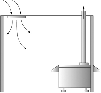
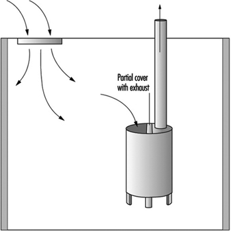
General room ventilation—for example, 4.25 m3/min supply and 4.8 m3/min exhaust (equivalent to 10 air changes per hour in a 3 x 3 x 3-metre room), with a minimum outside air replenishment rate of 0.15 m3/min per m2 floor area—is usually adequate for photographers who undertake basic photoprocessing. An exhaust rate higher than a supply rate produces a negative pressure in the room and reduces the opportunity for gases or vapours to escape to adjoining areas. The exhaust air should be discharged outside the building to avoid redistributing potential air contaminants within the building. If the processor tanks are enclosed and have an exhaust (see figure 1), the minimum air supply and exhaust rate can probably be reduced.
Figure 1. Enclosed-machine ventilation
Some operations (e.g., toning, film cleaning, mixing operations and special processing procedures) may require supplementary local exhaust ventilation or respiratory protection. Local exhaust is important because it reduces the concentration of airborne contaminants that might otherwise be recirculated by the general dilution ventilation system.
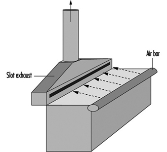
A lateral slot-type ventilation system for extracting vapours or gases at the surface of a tank may be used for some tanks. When designed and operated correctly, lateral slot-type exhausts draw clean air across the tank and remove contaminated air from the operator’s breathing zone and the surface of the processing tanks. Push-pull lateral slot-type exhausts are the most effective systems (see figure 2).
Figure 2. Open-tank with "push-pull" ventilation
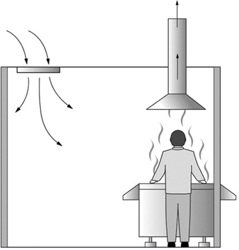
A hooded or canopy exhaust system (see figure 3) is not recommended because operators often lean over tanks with their heads under the hood. In this position, the hood draws vapours or gases into the operator’s breathing zone.
Figure 3. Overhead canopy exhaust
Split-tank covers with local exhaust attached to the stationary portion on mixing tanks may be used to supplement general room ventilation in mixing areas. Tank covers (tight-fitting covers or floating lids) should be used to prevent the release of potential air contaminants from storage and other tanks. A flexible exhaust may be attached to tank covers to facilitate the removal of volatile chemicals (see figure 4). As appropriate, automixers, which allow individual parts of multicomponent products to be added directly to and subsequently mixed in processors, should be used because they decrease the potential for operator exposure to photochemicals.
Figure 4. Chemical mixing tank exhaust
When mixing dry chemicals, the containers should be emptied gently to minimize chemical dust from becoming airborne. Tables, benches, shelves and ledges should be wiped with a water-dampened cloth frequently to keep residual chemical dust from accumulating and later becoming airborne.
Facility and operations design
Surfaces that may be contaminated with chemicals should be constructed to permit flushing with water. Adequate provisions should be made for floor drains, particularly in storage, mixing and processing areas. Because of the potential for leaks or spills, arrangements should be made for containment, neutralization and proper disposal of photochemicals. Since floors may be wet at times, flooring around potentially wet areas should be covered with non-skid tape or paint for safety purposes. Consideration should also be given to potential electrical hazards. For electrical devices used in or near water, ground-fault circuit interrupters and appropriate grounding should be used.
As a general rule, photochemicals should be stored in a cool (at temperatures no lower than 4.4 °C), dry (relative humidity between 35 and 50%), well-ventilated area, where they can be easily inventoried and retrieved. Chemical inventories should be actively managed so that the quantities of hazardous chemicals stored can be minimized and so that materials are not stored beyond their expiration dates. All containers should be properly labelled.
Chemicals should be stored to minimize the likelihood of container breakage during storage and retrieval. Chemical containers should not be stored where they can fall over, above eye level or where personnel have to stretch to reach them. Most hazardous materials should be stored at a low level and on a firm base in order to avoid possible breakage and spilling on the skin or eyes. Chemicals that, if accidentally mixed, might lead to fire, explosion or toxic chemical release should be segregated. For example, strong acids, strong bases, reducers, oxidizers and organic chemicals should be stored separately.
Flammable and combustible liquids should be stored in approved containers and storage cabinets. Storage areas should be kept cool, and smoking, open flames, heaters or anything else that might cause accidental ignition should be prohibited. During transfer operations, it should be ensured that containers are properly bonded and grounded. The design and operation of storage and handling areas for flammable and combustible materials should comply with applicable fire and electrical codes.
Whenever possible, solvents and liquids should be dispensed by metering pumps rather than by pouring. Pipetting of concentrated solutions and establishing siphons by mouth should not be permitted. The use of pre-weighed or pre-measured preparations may simplify operations and reduce the opportunities for accidents. Careful maintenance of all pumps and lines is necessary to avoid leakage.
Good personal hygiene should always be practiced in photoprocessing areas. Chemicals should never be placed in beverage or food containers or vice versa; only containers intended for chemicals should be used. Food or drink should never be brought into areas where chemicals are used, and chemicals should not be stored in refrigerators used for food. After handling chemicals, hands should be washed thoroughly, especially before eating or drinking.
Training and education
All personnel, including maintenance and housekeeping, should be trained in safety procedures relevant to their job tasks. An education programme for all personnel is essential in promoting safe work practices and preventing accidents. The educational programme should be carried out before personnel are allowed to work, at regular intervals thereafter and whenever new potential hazards are introduced into the workplace.
Summary
The key to working safely with photoprocessing chemicals is to understand the potential hazards of exposure and to manage the risk to an acceptable level. Risk management strategies for controlling potential occupational hazards in photoprocessing should include:
- providing personnel with training on potential hazards and safety procedures in the workplace,
- encouraging personnel to read and understand hazard communication vehicles (e.g., safety data sheets and product labels),
- maintaining workplace cleanliness and good personal hygiene,
- making certain that processors and other equipment are installed, operated and maintained to manufacturers’ specifications,
- substituting with less hazardous or less odorous chemicals, where possible,
- using engineering controls (e.g., general and local exhaust ventilation systems) where applicable,
- using protective equipment (e.g., protective gloves, goggles or face shield) when necessary,
- establishing procedures to ensure prompt medical attention for anyone with evidence of injury, and
- consideration of environmental exposure monitoring and health monitoring of employees as a verification of effective risk management strategies.
Additional information on black-and-white processing is discussed in the Entertainment and the arts chapter.
Overview of Environmental Issues
Major Environmental Issues
Solvents
Organic solvents are used for a number of applications in the printing industry. Major uses include cleaning solvents for presses and other equipment, solubilizing agents in inks, and additives in fountain solutions. In addition to general concerns about volatile organic compound (VOC) emissions, some potential solvent components may be persistent in the environment or have high ozone-depleting potential.
Silver
During black-and-white and colour photographic processing, silver is released into some of the processing solutions. It is important to understand the environmental toxicology of silver so that these solutions can be properly handled and disposed of. While free silver ion is highly toxic to aquatic life, its toxicity is much lower in a complexed form as in photoprocessing effluent. Silver chloride, silver thiosulphate and silver sulphide, which are forms of silver commonly observed in photoprocessing, are over four orders of magnitude less toxic than silver nitrate. Silver has a high affinity for organic material, mud, clay and other matter found in natural environments, and this lessens its potential impact in aquatic systems. Given the extremely low level of free silver ion found in photoprocessing effluents or in natural waters, control technology appropriate to complexed silver is sufficiently protective of the environment.
Other photoprocessing effluent characteristics
The composition of photographic effluent varies, depending on the processes being run: black-and-white, colour reversal, colour negative/positive or some combination of these. Water comprises 90 to 99% of the effluent volume, with the majority of the remainder being inorganic salts that function as buffers and fixing (silver halide-solubilizing) agents, iron chelates, such as FeEthylene diamine tetra-acetic acid, and organic molecules that serve as developing agents and anti-oxidants. Iron and silver are the significant metals present.
Solid waste
Every component of the printing, photography and reproduction industries generates solid waste. This can consist of packaging waste such as cardboard and plastics, consumables such as toner cartridges or waste material from operations such as scrap paper or film. Increasing pressure on industrial generators of solid waste has led businesses to examine carefully options to lower solid waste through reduction, reuse or recycling.
Equipment
Equipment plays an obvious role in determining the environmental impact of the processes used in the printing, photography and reproduction industries. Beyond this, scrutiny is increasing on other aspects of equipment. One example is energy efficiency, which relates back to the environmental impact of the energy generation. Another example is “takeback legislation”, which requires the manufacturers to receive equipment back for proper disposal after its useful commercial life.
Control Technologies
The effectiveness of a given control methodology can be quite dependent on the specific operating processes of a facility, the size of that facility and the necessary level of control.
Solvent control technologies
Solvent use can be reduced in several ways. More volatile components, such as isopropyl alcohol, can be replaced with compounds having lower vapour pressure. In some situations, solvent-based inks and washes can be replaced with water-based materials. Many printing applications need improvements in water-based options to compete effectively with solvent-based materials. High-solids ink technology can also result in reduction of organic solvent use.
Solvent emissions can be lowered by reducing the temperature of dampening or fountain solutions. In limited applications, solvents can be captured on adsorptive materials such as activated carbon, and reused. In other instances, windows of operation are too strict to allow captured solvents to be reused directly, but they may be recaptured for recycling offsite. Solvent emissions may be concentrated in condenser systems. These systems consist of heat exchangers followed by a filter or electrostatic precipitator. The condensate passes through an oil-water separator before ultimate disposal.
In larger operations, incinerators (sometimes called afterburners) can be used to destroy emitted solvents. Platinum or other precious metal materials may be used to catalyze the thermal process. Non-catalyzed systems must operate at higher temperatures but are not sensitive to processes that can poison catalysts. Heat recovery is generally necessary to make non-catalyzed systems cost effective.
Silver recovery technologies
The level of silver recovery from photoeffluent is controlled by the economics of recovery and/or by solution discharge regulations. Major silver recovery techniques include electrolysis, precipitation, metallic replacement and ion exchange.
In electrolytic recovery, current is passed through the silver-bearing solution and silver metal is plated on the cathode, usually a stainless steel plate. The silver flake is harvested by flexing, chipping or scraping and sent to a refiner for reuse. Attempting to lower the residual solution silver level significantly below 200 mg/l is inefficient and can result in formation of undesired silver sulphide or noxious sulphurous byproducts. Packed-bed cells are capable of reducing silver to lower levels but are more complex and expensive than cells with two-dimensional electrodes.
Silver may be recovered from solution by precipitation with some material that forms an insoluble silver salt. The most common precipitating agents are trisodium trimercaptotriazine (TMT) and various sulphide salts. If a sulphide salt is used, care must be taken to avoid generation of highly toxic hydrogen sulphide. TMT is an inherently safer alternative recently introduced to the photoprocessing industry. Precipitation has a recovery efficiency of greater than 99%.
Metallic replacement cartridges (MRCs) allow the flow of the silver-bearing solution over a filamentous deposit of iron metal. Silver ion is reduced to silver metal as iron is oxidized to ionic soluble species. The metallic silver sludge settles to the bottom of the cartridge. MRCs are not appropriate in areas where iron in the effluent is a concern. This method has a recovery efficiency of greater than 95%.
In ion exchange, anionic silver thiosulphate complexes exchange with other anions on a resin bed. When the capacity of the resin bed is exhausted, additional capacity is regenerated by stripping the silver with a concentrated thiosulphate solution or converting the silver to silver sulphide under acidic conditions. Under well-controlled conditions, this technique can lower silver below 1 mg/l. However, ion-exchange can be used only on solutions dilute in silver and thiosulphate. The column is extremely sensitive to stripping if the thiosulphate concentration of the influent is too high. Also, the technique is very labour- and equipment-intensive, making it expensive in practice.
Other photoeffluent control technologies
The most cost-efficient method to handle photographic effluent is via biological treatment at a secondary waste treatment plant (often referred to as a publicly owned treatment works, or POTW). Several constituents or parameters of photographic effluent may be regulated by sewer discharge permits. In addition to silver, other common regulated parameters include pH, chemical oxygen demand, biological oxygen demand and total dissolved solids. Multiple studies have demonstrated that photoprocessing wastes (including the small amount of silver remaining after reasonable silver recovery) following biological treatment are not expected to have an adverse effect on the receiving waters.
Other technologies have been applied to photoprocessing wastes. Haul-away for treatment in incinerators, cement kilns or other ultimate disposal is practised in some regions of the world. Some laboratories reduce the volume of solution to be hauled away through evaporation or distillation. Other oxidative techniques such as ozonation, electrolysis, chemical oxidation and wet air oxidation have been applied to photoprocessing effluents.
Another major source of reduced environmental burden is through source reduction. The level of silver coated per square metre in sensitized goods is steadily decreasing as new generations of products enter the marketplace. As the silver levels in media decrease, the amount of chemicals necessary to process a given area of film or paper has also decreased. Regeneration and reuse of solution overflows have also resulted in less environmental burden per image. For example, the amount of colour developing agent required to process a square metre of colour paper in 1996 is less than 20% of that required in 1980.
Solid-waste minimization
The desire to minimize solid waste is encouraging efforts to recycle and reuse materials rather than dispose of them in landfills. Recycling programmes exist for toner cartridges, film cassettes, single-use cameras and so on. Recycling and reuse of packaging is becoming more prevalent as well. More packaging and equipment parts are being labelled appropriately to allow more efficient material recycling programmes.
Life cycle analysis design for the environment
All of the issues discussed above have resulted in increasing consideration of the entire life cycle of a product, from procuring of natural resources to creating the products, to dealing with end-of-life issues for these products. Two related analytic tools, life cycle analysis and design for the environment, are being used to incorporate environmental issues into the decision-making process in product design, development and sales. Life cycle analysis takes into consideration all of the inputs and material flows for a product or process and attempts to quantitatively measure the impact on the environment of different options. Design for the environment brings into consideration various aspects of product design such as recyclability, reworkability and so on to minimize the impact on the environment of the production or disposal of the equipment in question.
Health Issues and Disease Patterns
Interpreting the human health data in the printing, commercial photographic processing and reproduction industry is no simple matter, since the processes are complex and are continually evolving - sometimes dramatically. While the use of automation has substantially reduced manual work exposures in modernized versions of all three of the disciplines, work volume per employee has increased substantially. Furthermore, dermal exposure represents an important route of exposure for these industries, yet is less well characterized by available industrial hygiene data. Case reporting of the less serious, reversible effects (e.g., headaches, nose and eye irritation) is incomplete and under-reported in the published literature. Despite these challenges and limitations, epidemiological studies, health surveys and case reports provide a substantial amount of information regarding the health status of workers in these industries.
Printing Activities
Agents and exposures
Today there are five categories of printing processes: flexography, gravure, letterpress, lithography and screen printing. The type of exposure that can occur from each process is related to the types of printing inks that are used and to the likelihood of inhalation (mists, solvent fumes and so on) and penetrable skin contact from the process and cleaning activities employed. It should be noted that the inks are composed of organic or inorganic pigments, oil or solvent vehicles (i.e., carriers), and additives applied for special printing purposes. Table 1 outlines some characteristics of different printing processes.
Table 1. Some potential exposures in the printing industry
|
Process |
Type of ink |
Solvent |
Potential exposures |
|
Flexography and gravure |
Liquid inks (low viscosity) |
Volatiles |
Organic solvents: xylene, benzene |
|
Letterpress and lithography |
Paste inks (high viscosity) |
Oils— |
Ink mist: hydrocarbon solvents; isopropanol; polycyclic aromatic hydrocarbons (PAHs) |
|
Screen printing |
Semipaste |
Volatiles |
Organic solvents: xylene, cyclohexanone, butyl acetate |
Mortality and chronic risks
Several epidemiological and case-report studies exist on printers. Exposure characterizations are not quantified in much of the older literature. However, respirable-size carbon black particles with potentially carcinogenic polycyclic aromatic hydrocarbons (benzo(a)pyrene) bound to the surface have been reported in rotary letterpress printing machine rooms of newspaper production. Animal studies find the benzo(a)pyrene tightly bound to the surface of the carbon black particle and not easily released to lung or other tissues. This lack of “bioavailability” makes it more difficult to determine whether cancer risks are feasible. Several, but not all, cohort (i.e., populations followed through time) epidemiological studies have found suggestions of increased lung cancer rates in printers (table 2). A more detailed assessment of over 100 lung cancer cases and 300 controls (case-control type study) from a group of over 9,000 printing workers in Manchester, England (Leon, Thomas and Hutchings 1994) found that the duration of work in a machine room was related to lung cancer occurrence in rotary letterpress workers. Since smoking patterns of the workers are not known, direct consideration of the role of occupation in the study is unknown. However, it is suggestive that rotary letterpress work may have presented a lung cancer risk in previous decades. In some areas of the world, however, older technologies, such as rotary letterpress work, may still exist and thus afford opportunities for preventive assessments, as well as installation of appropriate controls where needed.
Table 2. Cohort studies of printing trade mortality risks
|
Population studied |
Number of workers |
Mortality risks* (95% C.I.) |
||||
|
Follow-up period |
Country |
All causes |
All cancers |
Lung cancer |
||
|
Newspaper pressmen |
1,361 |
(1949–65) – 1978 |
USA |
1.0 (0.8–1.0) |
1.0 (0.8–1.2) |
1.5 (0.9–2.3) |
|
Newspaper pressmen |
,700 |
(1940–55) – 1975 |
Italy |
1.1 (0.9–1.2) |
1.2 (0.9–1.6) |
1.5 (0.8–2.5) |
|
Typographers |
1,309 |
1961–1984 |
USA |
0.7 (0.7–0.8) |
0.8 (0.7–1.0) |
0.9 (0.6–1.2) |
|
Printers (NGA) |
4,702 |
(1943–63) – 1983 |
UK |
0.8 (0.7–0.8) |
0.7 (0.6–0.8) |
0.6 (0.5–0.7) |
|
Printers (NATSOPA) |
4,530 |
(1943–63) – 1983 |
UK |
0.9 (0.9–1.0) |
1.0 (0.9–1.1) |
0.9 (0.8–1.1) |
|
Rotogravure |
1,020 |
(1925–85) – 1986 |
Sweden |
1.0 (0.9–1.2) |
1.4 (1.0–1.9) |
1.4 (0.7–2.5) |
|
Paperboard printers |
2,050 |
(1957–88) – 1988 |
USA |
1.0 (0.9–1.2) |
0.6 (0.3–0.9) |
0.5 (0.2–1.2) |
* Standardized Mortality Ratios (SMR) = number of observed deaths divided by number of expected deaths, adjusted for age effects over the time periods in question. An SMR of 1 indicates no difference between observed and expected. Note: 95% confidence intervals are provided for the SMRs.
NGA = National Graphical Association, UK
NATSOPA = National Society of Operative Printers, Graphical and Media Personnel, UK.
Sources: Paganini-Hill et al. 1980; Bertazzi and Zoccheti 1980; Michaels, Zoloth and Stern 1991; Leon 1994; Svensson et al. 1990; Sinks et al. 1992.
Another group of workers that has been substantially studied are lithographers. Modern lithographers’ exposure to organic solvents (turpentine, toluene and so on), pigments, dyes, hydroquinone, chromates and cyanates has been markedly reduced in recent decades due to the use of computer technologies, automated processes and changes in materials. The International Agency for Research on Cancer (IARC) recently concluded that occupational exposures in printing process are possibly carcinogenic to humans (IARC 1996). At the same time, it may be important to point out that IARC’s conclusion is based on historical exposures which, in most cases, should be significantly different today. Reports of malignant melanoma have suggested risks about twice the expected rate (Dubrow 1986). While some postulate that skin contact with hydroquinone could be related to melanoma (Nielson, Henriksen and Olsen 1996), it has not been confirmed in a hydroquinone manufacturing plant where significant exposure to hydroquinone was reported (Pifer et al. 1995). However, practices which minimize skin contact with solvents, particularly in plate cleaning, should be emphasized.
Photographic Processing Activities
Exposures and agents
Photographic processing of black-and-white or colour film or paper can be done either manually or by essentially fully automated larger-scale processes. The selection of the process, chemicals, working conditions (including ventilation, hygiene and personal protective equipment) and workload can all influence the types of exposures and potential health issues of the occupational environment. The types of jobs (i.e., processor-related tasks) having the greatest potential for exposure to key photographic chemicals, such as formaldehyde, ammonia, hydroquinone, acetic acid and colour developers, are noted in table 3. The typical photographic processing and handling work flow is depicted in figure 1.
Table 3. Tasks in photographic processing with chemical exposure potential
|
Work area |
Tasks with exposure potential |
|
Chemical mixing |
Mix chemicals into solution. |
|
Analytical laboratory |
Handle samples. |
|
Film/print processing |
Process film and print using developers, hardeners, bleaches. |
|
Film/print take-off |
Remove processed film and prints for drying. |
Figure 1. Photographic processing operations
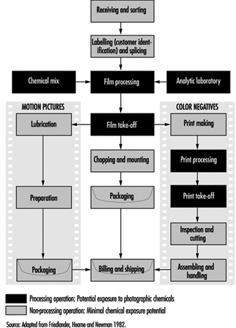
In more recently designed high-volume processing units, some of the steps in the workflow have been combined and automated, making inhalation and skin contact less likely. Formaldehyde, an agent that has been used for decades as a colour image stabilizer, is diminishing in concentration in photographic product. Depending on the specific process and site environmental conditions, its air concentration may range from non-detectable levels in the operator’s breathing zone up to about 0.2 ppm at machine dryer vents. Exposures can also occur during equipment cleaning, making or replenishing stabilizer fluid and unloading processors, as well as in spill situations.
It should be noted that while chemical exposures have been the primary focus of most health studies of photographic processors, other work environmental aspects, such as reduced light, materials handling and the postural demands of the job, are also of preventive health interest.
Mortality risks
The only published mortality surveillance of photographic processors suggests no increased risks of death for the occupation (Friedlander, Hearne and Newman 1982). The study covered nine processing laboratories in the United States, and was updated to cover 15 more years of follow-up (Pifer 1995). It should be noted that this is a study of over 2,000 employees who were actively working at the beginning of 1964, with over 70% of them having had at least 15 years of employment in their profession at that time. The group was followed for 31 years, through 1994. Many exposures relevant earlier in the careers of these employees, such as carbon tetrachloride, n-butylamine, and isopropylamine, were discontinued in the laboratories over thirty years ago. However, many of the key exposures in modern laboratories (i.e., acetic acid, formaldehyde and sulphur dioxide) were also present in previous decades, albeit at much higher concentrations. During the 31-year follow-up time period, the standardized mortality ratio was only 78% of that expected (SMR 0.78), with 677 deaths in the 2,061 workers. No individual causes of death were significantly increased.
The 464 processors in the study also had reduced mortality, whether compared to the general population (SMR 0.73) or to other hourly workers (SMR 0.83) and had no significant increases in any cause of death. Based on available epidemiological information, it does not appear that photographic processing presents an increased mortality risk, even at the higher concentrations of exposure likely to have been present in the 1950s and 1960s.
Pulmonary disease
The literature has very few reports of pulmonary disorders for photographic processors. Two articles, (Kipen and Lerman 1986; Hodgson and Parkinson 1986) describe a total of four potential pulmonary responses to processing workplace exposures; however, neither had quantitative environmental exposure data to assess the measured pulmonary findings. No increases in longer-term illness absence for pulmonary disorders was identified in the only epidemiological review of the subject (Friedlander, Hearne and Newman 1982); however, it is important to note that illness-absences of eight consecutive days were required in order to be captured in that study. It appears that respiratory symptoms can be aggravated or initiated in sensitive individuals by exposure to higher concentrations of acetic acid, sulphur dioxide and other agents in photographic processing, should ventilation be poorly controlled or errors occur during mixing, resulting in the release of undesired concentrations of these agents. However, work-related pulmonary cases have only rarely been reported in this occupation (Hodgson and Parkinson 1986).
Acute and subchronic effects
Contact irritative and allergic dermatitis has been reported in photographic processors for decades, starting with the initial use of colour chemicals in the late 1930s. Many of these cases occurred in the first few months of a processor’s exposure. The use of protective gloves and improved handling processes have substantially reduced photographic dermatitis. Eyesplashes with some photochemicals can present risks of corneal injury. Training on eyewash procedures (flushing eyes with cool water for at least 15 minutes followed by medical attention) and the use of protective eyewear is particularly important for photoprocessors, many of whom may work in isolation and/or in diminished light environments.
Some ergonomics concerns exist regarding the operation of rapid-turnaround, high-volume photographic processing units. The mounting and dismounting of large rolls of photographic paper can present a risk of upper back, shoulder and neck disorders. The rolls can weigh 13.6 to 22.7 kg (30 to 50 pounds), and may be awkward to handle, depending partly on access to the machine, which can be compromised in compact work sites.
Injuries and strains to the staff can be prevented by proper staff training, by provision of adequate access to the rolls and by considerations of human factors in the general design of the processing area.
Prevention and methods of early detection of effects
Protection from dermatitis, respiratory irritation, acute injury and ergonomic disorders starts with the recognition that such disorders can occur. With proper worker information (including labels, material safety data sheets, protective equipment and health protection training programmes), periodic health/safety reviews of the worksetting and informed supervision, prevention can be strongly emphasized. In addition, the early identification of disorders can be facilitated by having a medical resource for worker health reporting, coupled with targeted voluntary periodic health assessments, focusing on respiratory and upper extremity symptoms in questionnaires and direct observation of exposed skin areas for signs of work-related dermatitis.
Because formaldehyde is a potential respiratory sensitizer, a strong irritant and a possible carcinogen, it is important that each workplace be assessed to determine where formaldehyde is used (chemical inventory and material safety data sheet reviews), to assess air concentrations (if indicated by materials used), to identify where leaks or spills could occur and to estimate the quantity that could be spilled and the concentration generated in worst-case scenarios. An emergency response plan should be developed, conspicuously posted, communicated and periodically practised. A health and safety specialist should be consulted in the development of such an emergency plan.
Reproduction Activities
Agents and exposures
Modern photocopying machines emit very low levels of ultraviolet radiation through the glass cover (plenum), generate some noise and may emit low concentrations of ozone during the processing activity. These machines use a toner, primarily carbon black (for black-and-white printers), to produce a dark print on the paper or transparent film. Thus, potential routine exposures of health interest for photocopy operators can include ultraviolet radiation, noise, ozone and possibly toner. In older machines, toner could be an issue during replacement, although modern self-contained cartridges have substantially reduced potential respiratory and skin exposure.
The degree of ultraviolet radiation exposure that occurs through the copier machine platen glass is very low. The duration of a photocopier flash is approximately 250 microseconds, with continual copying making about 4,200 flashes per hour - a value that can vary depending upon the copier. With the glass platen in place, the emitted wavelength ranges from 380 to about 396 nm. UVB does not typically result from copier flashes. UVA measurements maximally recorded at the glass paten average about 1.65 microjoule/cm2 per flash. Thus, the maximum 8-hour near-UV spectral exposure from a continuously run photocopier making about 33,000 copies per day is approximately 0.05 joules/cm2 at the glass surface. This value is only a fraction of the threshold limit value recommended by the American Conference of Governmental Industrial Hygienists (ACGIH) and appears to present no measurable health risk, even in such exaggerated exposure conditions.
It should be noted that certain workers may be at higher risk for UV exposures, including those with photosensitive conditions, people using photosensitizing agents/medicines and people with impaired ocular pupils (aphakics). Such people are usually advised to minimize their UV exposures as a general precautionary measure.
Acute effects.
The literature does not reveal many acute effects meaningfully related to photocopying. Older, insufficiently maintained units could emit detectable ozone concentrations if run in poorly vented settings. While eye and upper respiratory irritation symptoms have been reported from workers in such environments, the minimum manufacturer specifications for space and ventilation, coupled with newer copier technology, have essentially eliminated ozone as an emission issue.
Mortality risks.
No studies were found that described mortality or chronic health risks from long-term photocopying.
Prevention and early detection
By simply following manufacturers’ recommended use, photocopying activity should not present a workplace risk. Individuals experiencing an aggravation of symptoms related to intense use of photocopiers should seek health and safety advice.
Reproduction and Duplicating Services
The modern office may contain several types of reproduction machines. They range from the ubiquitous dry-process photocopier to the rather special-purpose blueprint machine, the fax and mimeograph machines, as well as other types of duplicators. Within this article, the different devices will be grouped according to broad technology classes. Since dry-process photocopiers are so widespread, they will receive the greatest attention.
Photocopiers and Laser Printers
Processing operations
Most steps in conventional electrophotography (xerography) are directly analogous to those in photography. In the exposure step, the printed page or photograph to be copied is illuminated by a flash of bright light, and the reflected image is focused by a lens onto an electrically charged, light-sensitive photoreceptor, which loses its charge wherever the light hits its surface. The light will have hit in the same pattern as on the surface being copied. Next, developer, generally composed of large carrier beads with small, electrostatically charged particles adhering to them, is transported to the photoreceptor by a cascading or magnetic conveying process. The charged, latent image on the photoreceptor is developed when the finely divided powder (known as toner, dry imager or dry ink) is electrostatically attracted, separates out of the developer and remains on the image. Finally, the toner that has adhered to the imaged areas is electrostatically transferred (printed) to a sheet of plain paper and permanently fused to it (fixed) by the application of heat, or heat and pressure. Residual toner is removed from the photoreceptor by a cleaning process and deposited into a waste toner sump. The photoreceptor is then prepared for the next imaging cycle. Since the imaged paper removes only toner from the developer, the carrier that supplied it to the image is recirculated back into the developer housing and mixed with fresh toner that is metered into the system from a replaceable toner supply bottle or cartridge.
Many machines apply both pressure and heat to the toner-on-paper image during a fusing process. The heat is supplied by a fusing roll, which contacts the toned surface. Depending on the characteristics of the toner and fuser materials, some toner may stick to the fuser surface rather than to the paper, resulting in a deletion of part of the image on the copy. In order to prevent this, a fuser lubricant, commonly a silicone-based fluid, is applied to the surface of the fuser roll.
In laser printing, the image is first converted to an electronic format; that is, it is digitized into a series of very small dots (pixels) by a document scanner, or a digital image may be created directly in a computer. The digitized image is then written onto the photoreceptor in the laser printer by a laser beam. The remaining steps are essentially those of conventional xerography, wherein the image on the photoreceptor is transformed to paper or other surfaces.
Some photocopiers use a process known as liquid development. This differs from the conventional, dry process in that the developer is generally a liquid hydrocarbon carrier in which finely divided toner particles are dispersed. Development and transfer are generally analogous to the conventional processes, except that the developer is washed over the photoreceptor and the wet copy is dried by the evaporation of residual liquid upon the application of heat or both heat and pressure.
Materials
The consumables associated with photocopying are toners, developers, fuser lubricants and paper. Although not generally considered as consumables, photoreceptors, fuser and pressure rolls and various other parts routinely wear out and need replacement, especially in high-volume machines. These parts are generally not considered to be customer replaceable, and require special knowledge for their removal and the adjustment. Many new machines incorporate customer replaceable units (CRUs), which contain the photoreceptor and developer in a self-contained unit which the customer can replace. In these machines, the fuser rolls and so on either last the life of the machine or require separate repair. In a move toward reduced service costs and greater customer convenience, some companies are moving towards increased customer reparability, where repair can be made with no mechanical or electrical hazard risk to the customer and will, at most, require a telephone call to a support centre for assistance.
Toners produce the image on the finished copy. Dry toners are fine powders composed of plastics, colourants and small quantities of functional additives. A polymer (plastic) is usually the major component of a dry toner; styrene-acrylic, styrene-butadiene and polyester polymers are common examples. In black toners, different carbon blacks or pigments are used as the colourant, while in colour copying, various dyes or pigments are employed. During the toner manufacturing process, the carbon black or colourant and the polymer are melt mixed and most of the colourant becomes encapsulated by the polymer. Dry toners may also contain internal and/or external additives which help determine the toner’s static charging and/or flow characteristics.
Wet-process toners are similar to dry toners in that they consist of pigments and additives inside a polymer coating. The difference is that those components are purchased as a dispersion in an isoparaffinic hydrocarbon carrier.
Developers are usually mixtures of toner and carrier. Carriers literally carry toner to the surface of the photoreceptor and are frequently made of materials based on special grades of sand, glass, steel or ferrite types of substances. They may be coated with a small amount of polymer to achieve the desired behaviour in a specific application. Carrier/toner mixtures are known as two-component developers. Single-component developers do not use a separate carrier. Rather, they incorporate a compound like iron oxide into the toner and utilize a magnetic device for applying the developer to the photoreceptor.
Fuser lubricants are most often silicone-based fluids which are applied to fuser rolls to prevent toner offset from the developed image to the roll. While many are simple polydimethylsiloxanes (PDMSs), others contain a functional component to enhance their adhesion to the fuser roll. Some fuser lubricants are poured from a bottle into a sump, from which they are pumped and ultimately applied to the fuser roll. In other machines the lubricant may be applied via a saturated fabric web which wipes part of the roll’s surface, while in some smaller machines and printers, an oil-impregnated wick makes the application.
Most, if not all, modern photocopiers are made to perform well with various weights of ordinary, untreated bond paper. Special carbonless forms are made for some high-speed machines, and non-fusing transfer papers are produced for imaging in photocopiers and then applying the image to a T-shirt or other fabric with the application of heat and pressure in a press. Large engineering/architectural drawing copiers often produce their copies on a translucent velum.
Potential hazards and their prevention
Responsible manufacturers have worked hard to minimize the risk from any unique hazards in the photocopying process. However, material safety data sheets (MSDSs) should be obtained for any consumables or service chemicals used with a particular machine.
Perhaps the only unique material to which one may be significantly exposed in the photocopying process is toner. Modern, dry toners should not present a skin or eye hazard to any but perhaps the most sensitive individuals, and recently designed equipment utilizes toner cartridges and CRUs that minimize contact with bulk toner. Liquid toners, as well, should not be directly irritating to the skin. However, their isoparaffinic hydrocarbon carriers are solvents and can defat the skin, leading to dryness and cracking upon repeated exposure. These solvents may also be mildly irritating to the eyes.
Well-designed equipment will not present a bright light hazard, even if the platen is flashed with no original on it, and some illumination systems are interlocked with the platen cover to prevent any operator exposure to the light source. All laser printers are classified as Class I laser products, meaning that, under normal conditions of operation, the laser radiation (beam) is inaccessible, being contained within the printing process, and does not present a biological hazard. Additionally, the laser device should not require maintenance, and in the highly unusual event that access to the beam is required, the manufacturer must provide safe working procedures to be followed by a properly trained service technician.
Finally, properly manufactured hardware will not have sharp edges, pinch points or exposed shock hazards in areas where operators might place their hands.
Skin and eye hazards
In addition to dry toners not presenting a significant skin or eye hazard, one would expect the same with silicon oil-based fuser lubricants. Polydimethylsiloxanes (PDMSs) have been subjected to extensive toxicological evaluations and have generally been found to be benign. While some low-viscosity PDMSs may be eye irritants, those used as fuser lubricants usually are not, nor are they skin irritants. Regardless of actual irritation, any of these materials will be nuisances either on the skin or in the eyes. Affected skin may be washed with soap and water, and eyes should be flooded with water for several minutes.
Individuals frequently working with liquid toners, especially under potential splash conditions, may want to wear protective goggles, safety glasses with side shields, or a face shield if needed. Rubber or vinyl-coated gloves should prevent the dry skin problems mentioned above.
Papers are generally benign as well. However, there have been cases of significant skin irritation when proper care was not taken during processing. Poor manufacturing processes can also cause odour problems when the paper is heated in the fuser of a dry-process copier. Occasionally, the vellum in an engineering copier has not been properly processed and creates a hydrocarbon solvent odour problem.
In addition to the isoparaffinic base of liquid toners, numerous solvents are routinely used in machine upkeep. Included are platen and cover cleaners and film removers, which, typically, are alcohols or alcohol/water solutions containing small amounts of surfactants. Such solutions are eye irritants, but do not directly irritate the skin. However, like the liquid toner dispersants, their solvent action can defat skin and lead to eventual skin-cracking problems. Rubber or vinyl-coated gloves and goggles or safety glasses with side shields should be sufficient to preclude problems.
Inhalation hazards
Ozone is usually the greatest concern of those in the general vicinity of photocopiers. The next most readily identified concerns would be toner, including paper dust, and volatile organic compounds (VOCs). Some situations also give rise to odour complaints.
Ozone is primarily generated by corona discharge from the devices (corotrons/scorotrons) which charge the photoreceptor in preparation for exposure and cleaning. At concentrations most apt to be encountered in photocopying, it can be identified by its pleasant, clover-like odour. Its low odour threshold (0.0076 to 0.036 ppm) gives it good “warning properties”, in that its presence can be detected before it reaches harmful concentrations. As it reaches concentrations which might produce headaches, eye irritation and breathing difficulty, its odour becomes strong and pungent. One should not expect ozone problems from well-maintained machines in properly ventilated areas. However, ozone may be detected when operators work in the machine’s exhaust stream, especially in the case of long copy runs. Odours that are identified as ozone by inexperienced operators are usually found to have arisen from other sources.
Toner has long been considered to be a nuisance particulate, or “particulate not otherwise classified” (PNOC). Studies performed by Xerox Corporation in the 1980s indicated that inhaled toner elicits the pulmonary responses one would expect from exposure to such insoluble particulate materials. They also demonstrated a lack of carcinogenic hazard at exposure concentrations well above those expected to be found in the office environment.
Paper dust consists of paper fibre fragments and sizers and fillers such as clay, titanium dioxide and calcium carbonate. All of these materials are considered to be PNOCs. No reasons for concern have been found for the paper dust exposures expected to occur in the office environment.
The emission of VOCs by photocopiers is a byproduct of their use in plastic toners and parts, rubbers and organic lubricants. Even so, exposures to individual organic chemicals in the environment of an operating photocopier are usually orders of magnitude below any occupational exposure limits.
Odour problems with modern photocopiers are most often an indication of inadequate ventilation. Treated papers, such as carbonless forms or image transfer papers, and occasionally vellums used in engineering copiers, may produce hydrocarbon solvent odours, but exposures will be well below any occupational exposure limits if ventilation is adequate for normal copying. Modern photocopiers are complex electro-mechanical devices which have some parts (fusers) operating at elevated temperatures. In addition to odours that are present during normal operation, odours also occur when a part fails under a heat load and the smoke and emissions from hot plastic and/or rubber are released. Obviously, one should not remain in the presence of such exposures. Common to nearly all odour problems are complaints of nausea and some sort of eye or mucous membrane irritation. These complaints are usually simply indications of exposure to an unknown, and probably unpleasant, odour, and are not necessarily signs of significant acute toxicity. In such cases, the exposed individual should seek fresh air, which nearly always leads to a rapid recovery. Even exposures to smoke and vapours from overheated parts are usually of such short duration that there is no need for concern. Even so, it is only prudent to seek medical advice if symptoms persist or exacerbate.
Installation considerations
As discussed above, copiers produce heat, ozone and VOCs. While the siting and ventilation recommendations should be obtained from the manufacturer and should be followed, it is reasonable to expect that, for all but possibly the largest machines, location in a room having reasonable air circulation, more than two air changes per hour and adequate space around the machine for servicing will be sufficient to prevent ozone and odour issues. Naturally, this recommendation also assumes that all American Society of Heating, Refrigeration and Air Conditioning Engineers (ASHRAE) recommendations for room occupants are also met. If more than one photocopier is added to a room, care should be taken to provide added ventilation and cooling capability. Large, high-volume machines may require special heat-control considerations.
Supplies do not require special considerations beyond those for the keeping of any flammable solvents and avoiding excessive heat. Paper should be kept in its box to the extent practical and the wrapper should not be opened until the paper is needed.
Facsimile (Fax) Machines
Processing operations.
In facsimile reproduction, the document is scanned by a light source and the image is converted to an electronic form compatible with telephone communications. At the receiver, electro-optical systems decode and print the transmitted image via direct thermal, thermal transfer, xerographic or ink-jet processes.
Machines using the thermal processes have a linear print array like a printed circuit board, over which the copy paper is stepped during the printing process. There are about 200 contacts per inch across the width of the paper, which are rapidly heated when activated by an electric current. When hot, a contact either causes the contact spot on a treated copy paper to turn black (direct thermal) or the coating on a typewriter ribbon-like donor roll to deposit a black dot onto the copy paper (thermal transfer).
Fax machines which operate by the xerographic process use the telephone-transmitted signal to activate a laser beam and they then function the same as a laser printer. In a similar fashion, ink-jet machines function the same as ink-jet printers.
Materials.
Paper, either treated or plain, donor rolls, toner and ink are the major materials used in faxing. Direct thermal papers are treated with leuco dyes, which turn from white to black when heated. Donor rolls contain a mixture of carbon black in a wax and polymer base, coated onto a film substrate. The mixture is sufficiently firm that it does not transfer to the skin when rubbed, but when heated it will transfer to the copy paper. Toners and inks are discussed in the photocopying and ink-jet printing sections.
Potential hazards and their prevention.
No unique hazards have been associated with fax machines. There have been odour complaints with some early direct thermal machines; however, as with many odours in the office environment, the problem is more indicative of a low odour threshold, and possibly inadequate ventilation, than a health problem. Thermal transfer machines usually are odour free, and no hazards have been identified with the donor rolls. Xerographic fax machines have the same potential problems as dry photocopiers; however, their low speed normally precludes any inhalation concerns.
Blueprinting (Diazo)
Processing operations.
Modern references to “blueprints” or “blueprint machines” generally mean diazo copies or copiers. These copiers are most often used with large architectural or engineering drawings made on a film, vellum or translucent paper base. Diazo-treated papers are acidic and contain a coupler which yields a colour change upon reaction with the diazo compound; however, the reaction is prevented by the acidity of the paper. The sheet to be copied is placed in contact with the treated paper and exposed to intense ultraviolet (UV) light from a fluorescent or mercury vapour source. The UV light breaks the diazo bond on the areas of the copy paper not protected from exposure by the image on the master, eliminating the possibility of subsequent reaction with the coupler. The master is then removed from contact with the treated paper, which is then exposed to an ammonia atmosphere. The alkalinity of the ammonia developer neutralizes the acidity of the paper, permitting the diazo/coupler colour-change reaction to produce a copy of the image on the parts of the paper which were protected from the UV by the image on the master.
Materials.
Water and ammonia are the only diazo-process materials in addition to the treated paper.
Potential hazards and their prevention.
The obvious concern around diazo-process copiers is the exposure to ammonia, which can cause eye and mucous membrane irritation. Modern machines usually control emissions, and hence exposures are usually considerably less than 10 ppm. However, older equipment may require careful and frequent maintenance and possible local exhaust ventilation. Care should be taken when servicing a machine to avoid spills and prevent eye contact. Manufacturers’ recommendations regarding protective equipment should be followed. One should also be aware that improperly manufactured paper also has the potential for causing skin problems.
Digital Duplicators and Mimeographs
Processing operations.
Digital duplicators and mimeographs share the same basic process in that a master stencil is “burned” or “cut” and placed onto an ink-containing drum, from which ink flows through the master onto the copy paper.
Materials.
Stencils, inks and papers are the supplies used by these machines. The scanned image is digitally burned onto the mylar master of a digital duplicator, while it is electro-cut into a mimeograph’s paper stencil. A further difference is that digital duplicator inks are water based, though containing some petroleum solvent, while mimeograph inks are based on either a naphthenic distillate or a glycol ether/alcohol mixture.
Potential hazards and their prevention.
The primary hazards associated with digital duplicators and mimeographs are due to their inks, although there is a potential hot wax vapour exposure associated with burning the image onto the digital duplicator’s stencil and an ozone exposure during the electro-cutting of stencils. Both types of ink have the potential for eye and skin irritation, while mimeograph ink’s higher petroleum distillate content has a greater potential for causing dermatitis. The use of protective gloves while working with the inks, and adequate ventilation while making copies, should protect against skin and inhalation hazards.
Spirit Duplicators
Processing operations.
Spirit duplicators use a reverse-image stencil which is coated with an alcohol-soluble dye. In processing, the copy paper is lightly coated with a methanol-based duplicating fluid, which removes a small amount of dye upon coming in contact with the stencil, resulting in image transfer to the copy paper. The copies may emit methanol for some time after duplication.
Materials.
Paper, stencils and duplicating fluid are the main supplies for this equipment.
Potential hazards and their prevention.
Spirit duplicating fluids are usually methanol based, and hence are toxic if absorbed through the skin, inhaled or ingested; they are also flammable. Ventilation should be adequate to ensure operator exposures are below current occupational exposure limits and should include providing a ventilated area for drying. Some more recent duplicating fluids used are ethyl alcohol or propylene glycol based, which avoid the toxicity and flammability concerns of methanol. Manufacturers’ recommendations should be followed regarding the use of protective equipment when handling all duplicating fluids.
General Profile
The printing, commercial photography and reproduction industries are important worldwide in terms of their economic significance. The printing industry is very diverse in technologies and in size of enterprises. However, regardless of size as measured by production volume, the different printing technologies described in this chapter are the most common. In terms of production volume, there are a limited number of large-scale operations, but many small ones. From the economic perspective, the printing industry is one of the largest industries and generates annual revenues of at least US$500 billion worldwide. Similarly, the commercial photography industry is diverse, with a limited number of large-volume and many small-volume operations. Photofinishing volume is about equally divided between the large and small-volume operations. The commercial photographic market generates annual revenues of approximately US$60 billion worldwide, with photofinishing operations comprising approximately 40% of this total. The reproduction industry, which consists of smaller-volume operations with combined annual revenues of about US$27 billion, generates close to 2 trillion copies annually. In addition, reproduction and duplication services on an even smaller scale are provided onsite at most organizations and companies.
Health, environmental and safety issues in these industries are evolving in response to substitutions with potentially less hazardous materials, new industrial hygiene control strategies, and the advent of new technologies, such as the introduction of digital technologies, electronic imaging and computers. Many historically important health and safety issues (e.g., solvents in the printing industry or formaldehyde as a stabilizer in photoprocessing solutions) will not be issues in the future due to material substitution or other risk management strategies. Nevertheless, new health, environmental and safety issues will arise that will have to be addressed by health and safety professionals. This suggests the continued importance of health and environmental monitoring as part of an effective risk management strategy in the printing, commercial photography and reproduction industries.
Printing and Publication
General profile
The printing, commercial photography and reproduction industries are important worldwide in terms of their economic significance. The printing industry is very diverse in technologies and in size of enterprises. However, regardless of size as measured by production volume, the different printing technologies described in this chapter are the most common. In terms of production volume, there are a limited number of large-scale operations, but many small ones. From the economic perspective, the printing industry is one of the largest industries and generates annual revenues of at least US$500 billion worldwide. Similarly, the commercial photography industry is diverse, with a limited number of large-volume and many small-volume operations. Photofinishing volume is about equally divided between the large and small-volume operations. The commercial photographic market generates annual revenues of approximately US$60 billion worldwide, with photofinishing operations comprising approximately 40% of this total. The reproduction industry, which consists of smaller-volume operations with combined annual revenues of about US$27 billion, generates close to 2 trillion copies annually. In addition, reproduction and duplication services on an even smaller scale are provided onsite at most organizations and companies.
Health, environmental and safety issues in these industries are evolving in response to substitutions with potentially less hazardous materials, new industrial hygiene control strategies, and the advent of new technologies, such as the introduction of digital technologies, electronic imaging and computers. Many historically important health and safety issues (e.g., solvents in the printing industry or formaldehyde as a stabilizer in photoprocessing solutions) will not be issues in the future due to material substitution or other risk management strategies. Nevertheless, new health, environmental and safety issues will arise that will have to be addressed by health and safety professionals. This suggests the continued importance of health and environmental monitoring as part of an effective risk management strategy in the printing, commercial photography and reproduction industries.David Richardson
Overview of the Printing Processes
The invention of printing dates back to China in the 11th century. In the latter part of the 15th century, Johannes Gutenburg first introduced moveable type and invented the printing press, thus creating the process of printing that is now common around the world. Since then, the printing process has expanded dramatically beyond simply printing of words on paper to printing of words and other forms of graphic arts on paper and other materials (substrates). In the 20th century, the packaging of all types of consumer products has taken printing to yet another level. Printing, packaging and publications, along with the closely associated field of coating and laminating, are found in everyday products and processes used in the home, at leisure and at work.
The art of placing words and pictures on paper or other substrates is moving in directions not anticipated even a few years ago. A very wide spectrum of technologies, ranging from the older and more traditional styles of printing to the newest technologies involving computers and related processes has evolved. This includes everything from the older technology of lead-based type in flat-bed presses to today’s modern web-fed, direct-to-plate presses (see figure 1). In some operations, these varying technologies are literally found side by side.
Figure 1. The finishing end of a printing process
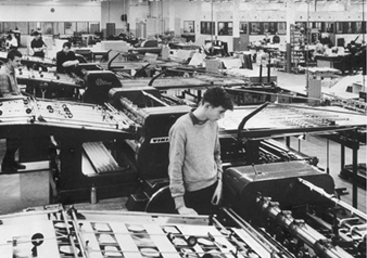
There are four general types of printing and there are many safety, health and environmental hazards associated with these technologies.
1. Letterpress or relief printing. This process, used for many years in printing and publication, involves the creation of images, often letters or pictures, that are raised above a background or non-printing area. Ink is applied to the raised area, which is then placed into contact with the paper or other substrate which accepts the image.
There are several ways to create the relief image, such as assembly of individual letters by using moveable type, or by using the once common linotype machine or machine-created type. These processes are appropriate for simpler, shorter run printing tasks. For longer-running tasks, printing plates, often made of metal or plastic or rubber-type materials, are more appropriate. Using rubber or similar plates is often called flexography or flexographic printing.
Inks typical of this process can be either solvent or water based. Some newer inks, based on ultraviolet (UV) curing and other chemico-physical systems, are being developed and implemented in this printing system.
2. Intaglio or gravure printing. In intaglio or gravure printing processes, the image to be printed is recessed into the face of an engraved plate or cylinder. The plate or cylinder is bathed in ink. Excess ink is then removed from the non-engraved parts of the plate by use of a doctor blade. The plate or cylinder is then brought into contact with the paper or other substrate to which the ink transfers the image. This system of printing is very typical of long-run printed products, such as magazines and packaging materials.
Inks typically are solvent based, with toluene being the most common solvent in intaglio or gravure inks. Use of inks based on soybean oil and water is under way with some success. However, not all applications can utilize this newer technology.
3. Planographic or lithography printing. Dissimilar materials form the basis for planographic or lithographic printing. By using dissimilar materials, areas can be developed that are water receptive or water repelling (i.e., receptive to solvent ink). The solvent ink-receptive area will carry the image, while the water-receptive area will become the background or unprinted area. Thus, ink adheres only in specific areas for transfer to the paper or other substrate. In many instances, this step will involve transfer to an intermediate surface, known as the blanket, which will later be placed against the paper or other substrate. This transfer process is called offset printing, which is widely used for many printing, publication and packaging applications.
It should be noted that not all offset printing involves lithography. Depending upon the exact needs of the printing process, other printing methods may utilize elements of offset printing.
Inks used in planographic or lithographic printing are usually solvent based (i.e., not water based), but some inks that are not solvent based are rapidly being developed.
4. Porous or screen printing. Porous or screen printing uses a stencil placed over a fine mesh screen. The ink is applied to the open screen areas and pressed (squeegeed) over the stencil and open mesh area. The ink will transfer through the screen to the paper or other substrate under the screen. Screen printing is often used for simpler, low volume printing tasks, where this process may have a cost advantage. Typical use of this printing process is for textiles, posters, displays and wallpaper.
Inks for screen printing are either solvent or water based, depending largely on the substrate to be printed. Since the coating used in screen printing is often thicker, inks are typically more viscous than those used in other printing methods.
Preparation of Print-Ready Material
Preparing material for printing involves assembling the various materials, including text, photographs, artwork, illustrations and designs, that are the subject of reproduction into the printed material. All materials must be completely finalized because changes cannot be made after print plates are created. In order to correct errors, the process must be redone. Principles of graphic arts are applied at this point to insure proper aesthetics of the printed product.
The health and safety aspects of the graphic arts step of the printing process are generally regarded as less hazardous than the other aspects of printing. The generation of artwork may involve considerable physical strain, as well as health risks from the pigments, rubber cement, spray adhesives and other materials used. Much of this is being replaced by computerized graphics which is also discussed in the article “Commercial art” in the Entertainment and the arts chapter. The potential hazards of working with visual display units and computers are discussed elsewhere in this Encyclopaedia. Ergonomically sound workstations can alleviate the hazards.
Platemaking
The printing plates or cylinders that are typical of contemporary printing processes must be created for either process photography or computer-generated make-up. Often, the platemaking starts with a camera system that is used to create an image, which subsequently may be transferred by photochemical methods to the plate. Colours must be separated, and aspects of the print quality such as halftone imagery must be developed in this process. The photography used for platemaking is very sophisticated when compared to the typical home-use of a camera. Exceptionally fine sharpness, colour separation and register are needed to allow for the production of quality printed materials. With the introduction of the computer, much of the manual assembly and image development work has been eliminated.
The potential hazards seen in this part of the printing process are similar to those typical of the photographic industry and are discussed elsewhere in this chapter. Controlling potential chemical exposures is important during platemaking.
After the image is created, photomechanical processes are used to create the printing plate. The typical photomechanical processes for making plates can be grouped into the following:
Manual methods. Hand tools, engravers and knives can be used to create relief in the plate, or crayons can be used to create water-repelling areas on a lithography plate. (This is generally a method used in small production, or for special printing tasks.)
Mechanical methods. Lathes, ruling machines and similar types of mechanical equipment are used to create relief, or other equipment can be used to produce water-repelling areas on lithography plates.
Electrochemical methods. Electrochemical methods are used to deposit metals onto plates or cylinders.
Electronic methods. Electronic engravers are used to create relief on plates or cylinders.
Electrostatic methods. Xerographic or similar methods are used to create either relief or water-repelling image components on plates or cylinders.
Photomechanical methods. Photographic images can be transferred to the plates through light-sensitive coatings on the plate or cylinder.
Photomechanical platemaking is the most common process today. In many instances, two or more systems may be used to create the plate or cylinder.
The health and safety implications of making printing plates are extensive owing to the various methods used to create the plate. Mechanical methods, less used today than in the past, were the source of typical mechanical safety issues, including hazards arising from the use of hand tools and the larger mechanical equipment often seen in the machine shop. Risks related to hand safety and guarding are typical in platemaking using mechanical methods. Such platemaking often involves the use of oils and cleaners that may be flammable or toxic.
Older methods are often still in use in many facilities right alongside newer equipment and hazards can be spread. If the plate consists of movable type, a linotype machine, once very common in most printshops, would make type by casting lead into the shape of letters. The lead is melted and kept in a lead pot. With the lead pot present, many of the hazards associated with lead come directly into the printshop. Lead, which is discussed elsewhere in this Encyclopaedia, can enter the body through inhalation of lead compounds and by skin contamination with lead and lead-containing type which can then lead to lead ingestion. The result is possible chronic low-grade lead poisoning, with resultant nervous system dysfunction, kidney dysfunction and other toxicity.
Other methods of platemaking use chemical systems typical of plating or chemical etching to create an image on the plate or cylinder. This involves many different chemicals, including acids and heavy metals (zinc, chromium, copper and aluminium), along with organic chemical-based resin systems that make up some of the upper layers of the plate itself. Some systems now use petroleum-based solvents in the chemical processes of making plates. The potential health hazards from such chemicals must be considered in the safety effort undertaken for such a facility. Ventilation and personal protective equipment that are appropriate for chemicals used are very important. Additionally, the potential environmental effects of corrosives and heavy metals need to be taken into account as part of the safety effort for the chemistry of platemaking. Storage and mixing of these chemical systems also presents health risks which can be significant if a spill occurs.
Engraving systems, used in some instances to transfer the image to the plate or cylinder, also may present potential hazards. Standard systems of engraving will generate some metal contamination that can be a problem for those working with these systems. The newer systems utilize laser equipment to carve the image into the plate material. While this allows the elimination of some steps in the platemaking process, the presence of the laser may present a hazard to the eyes and skin. The laser may also be used to soften materials, such as plastics, rather than to heat them to vapourization, thus creating additional vapour- and fume-related problems for the workplace.
In most instances, the platemaking process is a relatively small portion of the total production operations of the printing facility, which automatically limits the risk present, since few people work in the platemaking area and smaller quantities of materials are typical of these types of operations. As technology progresses, fewer steps will be needed to translate the image to the plate, thus presenting fewer opportunities for hazards to have an impact on employees and the environment.
Ink Manufacture
Depending upon the technologies utilized, a variety of inks and coatings are used. Inks are typically made up of a carrier and pigment or dyes and resins that go to form the image.
The carrier allows the pigments and other components to remain in solution until the ink is dried. Typical printing ink carriers include alcohols, esters (acetates), ketones or water. Gravure inks often include large amounts of toluene. Newer inks may contain epoxidized soybean oil and other chemicals that are less hazardous because they are not volatile.
Another component of typical inks is the resin binder. The resin bender is used, after the solvent has dried, to hold the pigment to the substrate. Organic resins, some natural and others synthetic, such as acrylic resins, are routinely used in inks.
The pigment provides the colour. Pigment bases can come from a variety of chemicals including heavy metals and organic materials.
UV-cured inks are based on acrylates and do not contain carriers. They are not involved in the curing/drying process. These inks tend to be simply a resin and pigment system. The acrylates are potential skin and respiratory sensitizers.
There are many health and safety hazards associated with ink manufacture. Since ink make-up often includes flammable solvents, fire protection is important at any facility where ink manufacture is undertaken. Sprinkler systems and portable extinguishing equipment must be present and in full and complete operating condition. Since employees must know how to use the equipment, training is needed. Electrical systems should be instrinsically safe or involve purging or explosion proofing. Control of static is critical since many solvents can generate a static charge when run through a plastic hose or through the air. Humidity control, grounding and bonding are strongly recommended for static control.
Mixing equipment, from small mixers to large batch tanks, can impose many mechanical safety hazards. Mixer blades and systems must be guarded or otherwise protected during operation and while in make-ready and clean-up modes. Machine guards are needed and must be in place; when they are removed for maintenance-related activities, lockout/tagout programmes are essential.
Owing to the quantities of materials present, the handling of material may also present hazards. While it is recommended that all materials that are conveniently piped directly to the area of use be handled in such a manner, many ink components must be manually moved to the mixing area in bags, drums or other containers. This involves using not only mechanical equipment such as lift trucks and hoists, but also manual handling by the employee doing the mixing. Back strains and similar stresses are common in these operations. Training on correct lifting practices is an important aspect of preventive measures, as well as selecting mechanical lifting processes that require less direct human involvement.
With this much handling, spills and chemical handling incidents can occur. Systems should be in place to deal with such emergency situations. Also, care in storage to prevent spillage and possible mixing of incompatible materials is needed.
The specific chemicals and large amounts stored can lead to issues related to possible employee health exposures. Each component, whether carrier, resin or pigment, should be evaluated both individually and within the context of the ink system. The safety effort should include: industrial hygiene evaluation and sampling to determine whether exposures are judged acceptable; adequate ventilation for removal of toxic materials; and the use of appropriate personal protective equipment should be considered. Since spills and other opportunities for overexposure are present, emergency systems should be in place to render first aid. Safety showers, eye washes, first aid kits and medical surveillance are all recommended, otherwise injury to skin, eyes, respiratory system and other body systems may occur. Inputs can range from simple dermatitis resulting from skin exposure to solvents, to more permanent organ damage due to exposure to heavy-metal pigments, such as lead chromate, that are found in some ink formulations. The spectrum of possible toxicity is large because of the many materials that are used in various ink and coating manufacture. With newer technologies such as UV-curable inks, the hazard may change from standard solvent hazards to sensitization from repeated contact with skin. Care must be taken to fully understand the potential risks of the chemicals used in ink and coating manufacture. This is best done prior to formulation.
Since many inks contain materials that are potentially harmful if they find their way into the environment, controls on the ink-making process may be necessary. Additionally, residual materials including clean-up materials and wastes must be handled carefully, to minimize their impact on the environment.
With the strong worldwide emphasis on a better environment, more “earth friendly” inks are being introduced, which use water as the solvent and less toxic resins and pigments. This should help reduce the hazards related to ink manufacturing.
Printing
Printing involves taking the plate, placing an ink onto the plate, and transferring the ink to the substrate. In offset processes, the image is transferred from a plate wrapped around a cylinder to an intermediate rubber cylinder (blanket) before being transferred to the desired substrate. Substrates are not always limited to paper, although paper is one of the most common substrates. Many fancy labels are printed on vacuum-metallized polyester film, using conventional printing techniques. Laminated plastics may be fed into the printing press in sheets or as part of a continuous web that is later cut to specification to make packaging.
Since printing often involves colour, several printed layers may be placed onto the substrate and then dried prior to the addition of the next layer. All of this must be done very precisely in order to keep all the colours in register. This requires multiple printing stations and sophisticated controls to maintain proper speed and tension through the press.
The hazards associated with operating a printing press are similar to those involved in ink manufacturing. The fire hazard is critical. As with ink manufacturing, sprinkler systems and other means of fire protection are needed. Other systems may be mounted directly to the press. These serve as added controls in addition to the portable extinguishers which should be available. Electrical systems should meet the purged, explosion-proof or intrinsically safe requirements. Static electricity control is also important, especially with solvents like isopropyl alcohol and with web presses. Added to the handling of flammable liquids that can generate static while moving through plastic hoses or the air, most plastic films or webs will also generate very substantial static charges when they move over a metal roll. Humidity control, grounding and bonding are necessary for removing static, along with web-focused static elimination techniques.
Manual handling of printing equipment, substrate materials and related inks is another safety concern. Storage issues similar to those in ink manufacture are present. Minimizing manual handling of equipment, substrate materials and inks is recommended. Where this is not possible, routine and focused education is needed for those employed in the printing room.
Added to the safety issues in the printing room are the mechanical safety issues involving rapidly moving/rotating equipment along with a substrate moving along at speeds in excess of 1,500 feet per minute. Guarding systems and alarms are needed to help insure employee safety. Lockout and tagout systems are also needed during repair/maintenance functions.
With the amount of rotating equipment and the speeds that are common in many printing operations, noise is often a significant issue, especially when multiple presses are present, as in newspaper printing. If noise levels are not acceptable, a hearing conservation programme should be implemented that includes engineering controls.
Although inks are often dried into the air around the press, drying tunnels are recommended to reduce exposure to volatile solvents.
Also, in some higher-speed printing operations, ink misting may occur. Both solvent drying and possible ink misting present a risk of inhalation of possibly toxic chemicals. Further, routine management of the printing operation, filling of tanks and trays, cleaning of rolls and idlers, and related tasks may involve contact with inks and cleaning solvents.
As with ink manufacturing, a well constructed industrial hygiene sampling effort, along with adequate ventilation and personal protective equipment, is recommended. Since these presses, some of which are very large, need to be routinely cleaned, chemical solvents are often used, leading to further chemical contact. Handling procedures can reduce exposures but not entirely remove them, depending on the size of the printing operations. As noted previously, even new inks and coatings that represent better technology still may have hazards. For example, UV-curable inks are potential sensitizers when in contact with the skin, and there is potential exposure to hazardous levels of UV radiation.
Emissions from printing operations, along with clean-up solutions and waste inks, are potential issues of environmental concern. Air pollution abatement systems may be needed to capture and either destroy or reclaim solvents evaporated from inks after printing. Careful management of the wastes generated to minimize the impact on the environment is important. Waste handling systems are recommended where solvents or other components can be recycled. Newer technology using better solvents for clean-up are coming from current research efforts. This may reduce emissions and possible exposures. An active review of current clean-up technology is recommended to see if alternatives to solvent cleaning, such as using water-based solutions or vegetable oils, are available that will meet the requirements found in specific printing operations. However, water-based cleaning solutions that are contaminated with solvent-based inks may still require careful management both inside the printing operation and upon disposal.
Finishing
Once printed, the substrate typically needs some additional finishing prior to being prepared for final use. Some materials can be sent directly from the press to packaging equipment which will form the package and fill in the contents or will apply an adhesive and place the label onto the container. In other instances, a large amount of cutting or slitting to size is needed for final assembly of the book or other printed material.
The health and safety issues related to finishing are mostly mechanical safety issues. Since much of the finishing involves cutting to size, cuts and lacerations to the fingers, hands and wrist/arm are typical. Guarding is important and must be used as part of every task. Small knives and blades used by employees also need to be used carefully and stored and disposed of properly to prevent inadvertent cuts and lacerations. Larger systems also need the same level of attention in guarding and training to prevent accidents.
The material handling aspect of finishing is significant. This applies to the material to be finished as well as the final packaged printed product. Where mechanical equipment such as lift trucks, hoists and conveyors can be used, they are recommended. Where manual lifting and handling must occur, education on proper lifting should be undertaken.
Recent evaluation of this component of the printing process indicates that possible ergonomic stress is placed on the human body. Each task - cutting, sorting, packaging - should be reviewed to determine possible ergonomic implications. If ergonomic problems are found, changes in the workplace may be needed to reduce this possible stressor to acceptable levels. Often some form of automation can help, but there still remain in most printing operations many manual handling tasks that may create ergonomic stress. Job rotation can help reduce this problem.
Printing in the Future
There will always be a need to print words on a substrate. But the future of printing will involve more direct transfer of information from computer to press, as well as electronic printing, where words and images are impressed onto electromagnetic media and other substrates. While such electronic print can be viewed and read only through an electronic device, more and more printed text and literature will move from the printed substrate to the electronic substrate format. This will lessen many of the mechanical safety and health issues related to printing, but will increase the number of ergonomic health risks in the printing industry.
More...
Synthetic Gems
Synthetic gems are chemically and structurally identical to stones found in nature. Imitation gems, in contrast, are stones that are made to appear similar to a particular gem. There are a few basic processes that produce a variety of gem stones. Synthetic gems include garnet, spinel, emerald, sapphire and diamond. Most of these stones are produced for use in jewellery. Diamonds are used as abrasives, while rubies and garnets are used in lasers.
The first synthetic gem used in jewellery was emerald. The process employed in its manufacture is proprietary and kept secret, but probably involves a flux-growth method in which silicates of alumina and beryllium with additions of chromium for colour are melted together. Emeralds crystallize out of the flux. It may take a year to produce stones by this process.
The Verneuil or flame-fusion process is used in the production of sapphire and ruby. It requires large amounts of hydrogen and oxygen, therefore consuming great amounts of energy. This process involves heating a seed crystal with an oxyhydrogen flame until the surface is liquid. Powered raw material such as AI2O3 for sapphire is added carefully. As the raw material becomes molten, the seed crystal is slowly withdrawn from the flame, causing the liquid furthest from the flame to solidify. The end closest to the flame is still liquid and ready for more raw material. The end result is the formation of a rod-like crystal. Sundry colours are created by adding small amounts of various metal ions to the raw materials. Ruby is created by replacing 0.1% of its aluminium ions with chromium atoms.
Spinel, a colourless synthetic germ (MgAI2O4), is made by the Verneuil process. Along with sapphire, spinel is used by industry to provide a wide range of colours for use as birth stones and in class rings. The colour produced by adding the same metal ions will be different in spinel than it will be in sapphire.
Synthetic diamonds are used in industry because of their hardness. Applications for diamonds include cutting, polishing, grinding and drilling. Some of the common uses are cutting and grinding of granite for use in building construction, well drilling and grinding non-ferrous alloys. In addition, processes are being developed that will deposit diamond on surfaces to provide clear, hard, scratch-resistant surfaces.
Diamonds are formed when elemental carbon or graphite is subjected to pressure and heat over time. To create a diamond on the factory floor involves combining graphite and metal catalysts and pressing them together in high heat (up to 1,500 °C). The size and quality of the diamonds are controlled by adjusting the time, pressure and/or heat. Large tungsten carbide dies are used to achieve the high pressures needed to form diamonds in a reasonable period of time. These dies measure up to 2 m across and 20 cm thick, resembling a large doughnut. The mixture of graphite and catalyst is placed in a ceramic gasket, and tapered pistons squeeze from above and below. After a specified time, the gasket containing diamonds is removed from the press. The gaskets are broken away and the diamond-bearing graphite is subjected to a series of agents designed to digest away all material except for the diamonds. The reactants employed are strong agents that are potential sources of significant burns and respiratory injury. Gem-quality diamonds may be produced in the same manner, but the long press times required make this process prohibitively expensive.
Hazards resulting from the manufacture of diamonds include potential exposure to the highly reactive acids and caustic agents in great volumes, noise, dust from forming and breaking of ceramic gaskets, and metal dust exposure. Another potential hazard is created by the failure of the massive carbide dies. After a variable number of uses, the dies fail, posing a trauma hazard if the dies are not isolated. Ergonomic issues arise when the diamonds manufactured are classified and graded. Their small size makes this a tedious and repetitive job.
Optical Fibres
Optical fibres are hair-thin strands of glass designed to transmit light rays along their axis. Light-emitting diodes (LEDs) or laser diodes convert electrical signals into the optical signals that are transmitted through an inner cylindrical core of the optical fibre cable. The lower refractive properties of the external cladding allows light signals to be propagated by internal reflection along the inner cylindrical core. Optical fibres are designed and manufactured to propagate either as a single light beam or as multiple light beams simultaneously transmitted along the core. (See figure 1.)
Figure 1. Single & multi-mode optical fibres
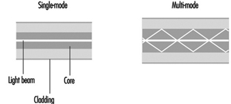
Single-mode fibre is primarily used for telephony, cable television applications and campus backbones. Multi-mode fibre is commonly used for data communications and in premise networks.
Optical fibre manufacturing
Special materials and processes are required to manufacture optical fibres that meet the basic design criteria: (1) a core with a high refractive index and cladding with a low refractive index, (2) a low signal attenuation or power loss, and (3) a low dispersion or broadening of the light beam.
High-purity silica glass with other glass materials (i.e., heavy-metal fluoride glasses, chalcogenide glasses) are the primary materials currently used to manufacture optical fibres. Polycrystalline materials, single-crystal materials, hollow waveguides and polymeric plastic materials are also used. Raw materials must be relatively pure with very low concentrations of transition metals and hydroxyl-forming groups (below the parts per billion level). Processing methods must shield the forming glass from impurities in the manufacturing environment.
Optical fibres are manufactured by using a non-conventional vapour phase preparation of a glass preform which is then drawn into fibre. Volatile silica compounds are converted to SiO2 by flame hydrolysis, chemical vapour deposition (CVD) or high-temperature oxidation. Other dopants are then added to the glass to change the glass properties. Variations in the process of vapour deposition start with the same material but differ in the method used to convert this material to silica.
One of the following vapour phase deposition methods is used to manufacture silica-based optical fibres: (1) modified chemical vapour deposition (MCVD), (2) plasma chemical vapour deposition (PCVD), (3) outside vapour deposition (OVD), and (4) vapour phase axial deposition (VAD) (see figure 2). Silicon tetrachloride (SiCI4), germanium tetrachloride (GeCI4) or other volatile liquid halides convert to gas when heated slightly due to their high vapour pressures. Gaseous halide is delivered to a reaction zone and converted to glass particles (see also the chapter Microelectronics and semiconductors.)
Figure 2. Optic fibre manufacturing flow chart
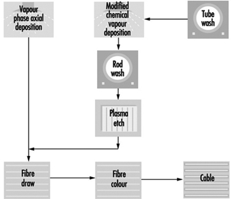
MCVD and PCVD processes. A high-quality fused silica tube is attached to a glass working lathe fitted with a hydrogen/oxygen torch that traverses its length. A halide material supply is attached to one end of the glass tube and a scrubber to the opposite end to remove excess halide material. The surface of the glass tube is first cleaned by fire polishing as the torch traverses the tube’s length. Various reagents are added in the vapour system depending on the product being manufactured. A chemical reaction occurs as the halides pass through the section of the tube being heated. The halides convert to silica “soot” particles that deposit on the inner glass tube wall downstream from the torch. Deposited particles are sintered into the glass layer. The PCVD process is similar to MCVD except that the halides are supplied by a bubbler system, and microwaves are used instead of a torch to convert the halide material to glass.
OVD and VAD processes. In the first stage of the fibre manufacturing process, the core and cladding glasses are vapour deposited around a rotating target rod to form a “soot” preform. The core material is deposited first, followed by the cladding. The entire preform must be extremely pure, since both the core and cladding are vapour deposited. Fibre geometry is determined during the laydown phase of manufacturing. After the target rod is removed, the preform is placed in a furnace, where it is consolidated into a solid, clear glass and the centre hole is closed. Gas is passed through the preform to remove residual moisture which adversely affects the attenuation of the fibre (loss of optical signal as light transmits along the fibre axis). Preforms are then washed with hydrofluoric acid to ensure the purity of the glass and to remove contaminants.
The consolidated glass preform is placed in a draw tower to form a continuous strand of glass fibre. First the preform is loaded into the top of a draw furnace. Next, the tip of the preform is heated and a piece of molten glass begins to fall. As this piece is drawn (pulled), it passes through an inline diameter monitor to assure the fibre meets an exact specified diameter (usually measured in microns.) The fibre’s cladding diameter must conform with exact specifications in order to keep signal loss at connections low. The outer cladding diameter is used as a guide to align fibre cores during end use. The cores must line up so light transfer occurs efficiently.
Acrylate polymer or other coatings are applied and cured with ultraviolet lamps. The coatings are intended to protect the optical fibre from the environment during end use. The optical fibres are tested to assure conformance with manufacturing standards for strength, attenuation and geometry. Specific lengths of fibre are wound onto reels per customer specifications.
A number of potential hazards are encountered during optical fibre manufacturing. These include: (1) exposure to hydrofluoric acid (when cleaning glass preforms), (2) radiant energy and heat stress associated with working environments near lathes and vapour deposition processes, (3) direct contact with hot surfaces or molten material (glass preforms), (4) exposure to acrylate polymer coatings (skin sensitizers), (5) skin punctures and lacerations during fibre handling and (6) a variety of physical hazards previously described.
Glass, Ceramics and Related Materials
This chapter covers the following product sectors:
- glass
- synthetic vitreous fibres
- pottery
- ceramic tile
- industrial ceramics
- brick and tile
- refractories
- synthetic gems
- optical fibres.
Interestingly, not only do most of these sectors have roots in antiquity, but they also share a number of common general processes. For example, all are fundamentally based on the use of naturally occurring raw materials in powder or fine particulate form which are transformed by heat into the desired products. Therefore, despite the range of processes and products encompassed in this group, these common processes allow a common overview of potential health hazards associated with these industries. Since the various manufacturing sectors are composed of both small, fragmented segments (e.g., brick manufacturing) and large, technically sophisticated manufacturing plants employing thousands of workers, each sector is described separately.
Common Processes and Hazards
There are common safety and health hazards encountered in manufacturing of products in these business sectors. The hazards and control measures are discussed in other sections of the Encyclopaedia. Process-specific hazards are discussed in the individual sections of this chapter.
Batch raw material processes
Most of the industrial manufacturing processes receive dry solid raw materials in bulk form or individual bags. Bulk solid raw materials are unloaded from hopper rail cars or over-the-road trucks into bins, hoppers or mixers by gravity, pneumatic transfer lines, screw conveyors, bucket conveyors or other mechanical transfer. Pallets of bagged raw materials (20 to 50 kg) or large bulk fabric bag containers (0.5 to 1.0 tonnes) are unloaded from truck trailers or rail boxcars by powered industrial lift trucks, cranes or hoists. Individual bags or raw materials are removed from pallets manually or with powered lift assists. Bagged raw materials are typically charged into a bag dumping station or directly into storage hoppers or scale hoppers.
Potential safety and health hazards associated with the solid raw material unloading, handling and transfer processes include:
- noise exposures in the 85 to 100 dBA range. Pneumatic vibrators, compressors, valve actuators, mixing drive motors, blowers, and dust collectors are some major noise sources.
- exposures to respirable airborne particulate from the transfer and mixing of granular solid raw materials. Exposures depend on composition of raw materials but may commonly include silica (SiO2), clay, alumina, limestone, alkaline dusts, metal oxides, heavy metals and nuisance particulate.
- ergonomic hazards associated with manual lifting or handling of raw material bags, vibrators, or transfer lines and system maintenance activities
- physical hazards from manoeuvring rail cars or trucks, powered-industrial truck traffic, work at elevated heights, confined-space entries and contact with electrical, pneumatic or mechanical energy sources—e.g., nip points, rotating parts, drive gears, shafts, belts and pulleys.
Firing or melting processes
Manufacturing products in these business sectors involves drying, melting or firing processes in kilns or furnaces. The heat for these processes is generated by combustion of propane, natural gas (methane) or fuel oil, electric arc melting, microwave, dielectric drying and/or resistance heating with electricity. Potential hazards presented from firing or melting processes include:
- exposures to combustion products such as carbon monoxide, nitrogen oxides (NOx) and sulphur dioxide
- fumes and particulates from airborne raw materials (e.g., silica, metals, alkaline dusts) or by-products (e.g., hydrogen fluoride, cristobalite, heavy metal fumes)
- fire or explosion associated with fuel systems used for process heat or fuel for lift trucks; potential fire or explosion hazards associated with flammable fuel storage tanks, piping distribution systems and vaporizers. Back-up or stand-by fuel systems in-frequently used for natural gas curtailments can present similar fire or explosion concerns.
- infrared radiation exposure from molten material, which can increase risk of heat cataracts or skin burns
- radiant energy and heat stress. The working environment around furnaces or kilns can be extremely hot. Significant heat stress problems can occur when emergency repair work or routine maintenance is performed near or above firing or melting processes. Severe thermal burns can result from direct skin contact with hot surfaces or molten materials (see figure 1).
Figure 1. Quality-control technician
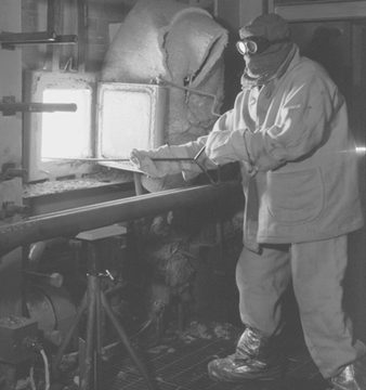
- electrical energy hazards. Direct contact with high-voltage electric energy used for resistance heating to supplement fuel-fired processes presents an electrocution hazard and possible health concerns about exposure to electromagnetic fields (EMF). Strong magnetic and electric fields can potentially interfere with pacemakers and other implanted medical devices.
- noise exposures above 85 to 90 dBA from combustion blowers, batch hoppers or mixers, feed processes and conveyors.
handling in production, fabrication, packaging and warehousing
Material-handling, fabrication and packaging processes differ to a large extent in this business sector, as do the size, shape and weights of products. The high density of materials in this sector or bulky configurations present common material-handling hazards. Manual lifting and material handling in production, fabrication, packaging and warehousing in this industry accounts for many disabling injuries. (See “Injury and illness profile” section below.) Injury reduction efforts are focusing on reducing manual lifting and material handling. For example, innovative packaging designs, robotics for stacking and palletizing finished products, and automatic guided transport vehicles for warehousing are starting to be used in select parts of this business sector to eliminate manual material handling and associated injuries. Use of conveyors, manned lift assists (e.g., vacuum hoists) and scissors platforms for handling and palletizing products are currently common material-handling practices (see figure 2).
Figure 2. Vacuum lift assist being used
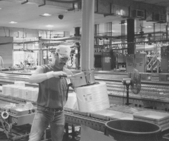
The use of robotics to eliminate manual material handling is playing a major role in prevention of ergonomic injuries. Robotics has reduced ergonomic stresses and severe laceration injuries that have been historically associated with material handling (e.g., flat glass) in the production workforce (see figure 3). However, increased utilization of robotics and process automation introduces moving machinery and electric power hazards, which transforms the types of hazards and also transfers risks to other workers (from production to maintenance workers). Proper designs of electronic controls and logic sequencing, machine guards, total energy lockout practices and establishing safe operating and maintenance procedures are fundamental ways to control injuries to maintenance and production workers.
Figure 3. Robotics used in plate-glass
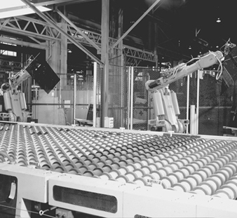
Rebuilds and reconstruction activities
Numerous potential health and safety hazards are encountered during periodic major rebuilds or cold repairs to furnaces or kilns. A wide range of hazards associated with construction activities may be encountered. Examples include: ergonomic hazards with material handling (e.g., refractory bricks); airborne exposures to silica, asbestos, refractory ceramic fibres or particulate matter containing heavy metal, during demolition, or by-products of cutting and welding; heat stress; work at elevated heights; slip, trip or fall hazards; confined-space hazards (see figure 4); and contact with hazardous energy sources.
Figure 4. Confined-space entry
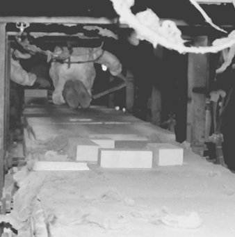
Glass
General profile
Glass was formed naturally from common elements in the earth’s crust long before anyone ever thought of experimenting with its composition, moulding its shape or putting it to the myriad of uses that it enjoys today. Obsidian, for instance, is a naturally occurring combination of oxides fused by intense volcanic heat and vitrified (made into a glass) by rapid air cooling. Its opaque, black colour comes from the relatively high amounts of iron oxide it contains. Its chemical durability and hardness compare favourably with many commercial glasses.
Glass technology has evolved for 6,000 years, and some modern principles date back to ancient times. The origin of the first synthetic glasses is lost in antiquity and legend. Faience was made by the Egyptians, who molded figurines from sand (SiO2), the most popular glass-forming oxide. It was coated with natron, the residue left by the flooding Nile river, which was composed principally of calcium carbonate (CaCO3), soda ash (Na2CO3), salt (NaCl) and copper oxide (CuO). Heating below 1,000 °C produced a glassy coating by the diffusion of the fluxes, CaO and Na2O into the sand and their subsequent solid-state reaction with the sand. The copper oxide gave the article an appealing blue colour.
According to the definition given by Morey: “Glass is an inorganic substance in a condition which is continuous with, and analogous to, the liquid state of that substance, but which, as the result of a reversible change in viscosity during cooling, has attained so high a degree of viscosity as to be, for all practical purposes, rigid.” ASTM defines glass as “an inorganic product of fusion that has cooled to a rigid condition without crystallizing.” Both organic and inorganic materials may form glasses if their structure is non-crystalline—that is, if they lack long-range order.
A most important development in glass technology was the use of a blow pipe (see figure 5), which was first used in approximately 100 years BC. From then onwards, there was a rapid development in the technique of manufacturing glass.
Figure 5. The blow pipe
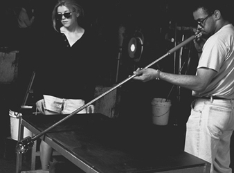
The first glass was coloured because of the presence of various impurities such as oxides of iron and chromium. Virtually colourless glass was first made some 1,500 years ago.
At that time glass manufacturing was developing in Rome, and from there it moved to many other countries in Europe. Many glass works were built in Venice, and an important development took place there. In the 13th century, many of the glass plants were moved from Venice to a nearby island, Murano. Murano is still a centre for the production of hand-made glass in Italy.
By the 16th century, glass was made all over Europe. Now Bohemian glass from the Czech Republic is well known for its beauty and glass plants in the United Kingdom and Ireland produce high-quality lead crystal glass tableware. Sweden is another country that is home to artistic glass crystalware production.
In North America the first manufacturing establishment of any sort was a glass factory. English settlers started to produce glass at the beginning of the 17th century at Jamestown, Virginia.
Today glass is manufactured in most countries all over the world. Many products of glass are made in fully automatic processing lines. Although glass is one of the oldest materials, its properties are unique and not yet fully understood.
The glass industry today is made up of several major market segments, which include the flat glass market, the consumer houseware market, the glass containers market, the optical glass industry and the scientific glassware market segment. The optical and scientific glass markets tend to be very ordered and are dominated by one or two suppliers in most countries. These markets are also much lower in volume than the consumer-based markets. Each of these markets has developed over the years by innovations in specific glass technology or manufacturing advancements. The container industry, for example, was driven by the development of high-speed bottle-making machines developed in the early 1900s. The flat glass industry was significantly advanced by the development of the float glass process in the early 1960s. Both of these segments are multi-billion-dollar businesses worldwide today.
Glass housewares fall into four general categories:
- tableware (including dinnerware, cups and mugs)
- drinkware
- bakeware (or ovenware)
- top-of-stove cookware.
While worldwide estimates are difficult to obtain, the market for glass housewares is undoubtedly on the order of US$1 billion in the United States alone. Depending upon the specific category, a variety of other materials compete for market share, including ceramics, metals and plastics.
Manufacturing processes
Glass is an inorganic product of fusion which has cooled to a rigid condition without crystallizing. Glass is typically hard and brittle and has a conchoidal fracture. Glass may be manufactured to be coloured, translucent or opaque by varying the dissolved amorphous or crystalline materials that are present.
When glass is cooled from the hot molten state, it gradually increases in viscosity without crystallization over a wide temperature range, until it assumes its characteristic hard, brittle form. Cooling is controlled to prevent crystallization, or high strain.
While any compound which has these physical properties is theoretically a glass, most commercial glasses fall into three main types and have a wide range of chemical compositions.
- Soda-lime-silica glasses are the most important glasses in terms of quantity produced and variety of use, including almost all flat glass, containers, low-cost mass-produced domestic glassware and electric light bulbs.
- Lead-potash-silica glasses contain a varying but often high proportion of lead oxide. Optical glass manufacture makes use of the high refractive index of this type of glass; hand-blown domestic and decorative glassware makes use of its ease of cutting and polishing; electrical and electronic applications takes advantage of its high electrical resistivity and radiation protection.
- Borosilicate glasses have a low thermal expansion and are resistant to thermal shock, which makes them ideal for domestic oven and laboratory glassware and for glass fibre for plastic reinforcements.
A commercial glass batch consists of a mixture of several ingredients. However, the largest fraction of the batch is made up of from 4 to 6 ingredients, chosen from such materials as sand, limestone, dolomite, soda ash, borax, boric acid, feldspathic materials, lead and barium compounds. The remainder of the batch consists of several additional ingredients, chosen from a group of some 15 to 20 materials commonly referred to as minor ingredients. These latter additions are added with a view to providing some specific function or quality, such as colour, which is to be realized during the glass preparation process.
Figure 6 illustrates the basic principles of glass manufacture. The raw materials are weighed, mixed and, after the addition of broken glass (cullet), taken to the furnace for melting. Small pots of up to 2 tonnes capacity are still used for the melting of glass for hand-blown crystalware and special glasses required in small quantity. Several pots are heated together in a combustion chamber.
Figure 6. The processes & materials involved
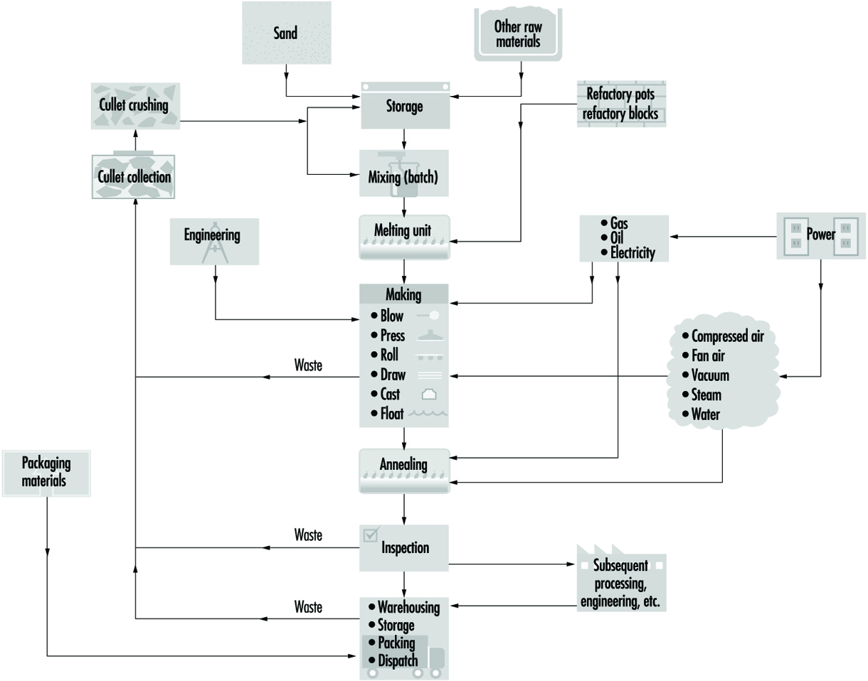
In most modern manufacture, melting takes place in large regenerative, recuperative or electric furnaces built of refractory material and heated by oil, natural gas or electricity. Electric boosting and cold top electric melting were commercialized and became extensively utilized globally in the late 1960s and 1970s. The driving force behind cold top electric melting was emission control, while electric boosting was generally used in order to improve glass quality and to increase throughput.
The most significant economic factors concerning the use of electricity for glass furnace melting are related to fossil fuel costs, the availability of various fuels, electricity costs, capital costs for equipment and so on. However, in many instances the prime reason for the use of electric melting or boosting is environmental control. Various locations worldwide either already have or are expected soon to have environmental regulations that strictly restrict the discharge of various oxides or particulate matter in general. Thus, manufacturers in many locations face the possibility of either having to reduce glass melting throughputs, install baghouses or precipitators in order to handle waste flue gases or modify the melting process and include electric melting or boost. The alternatives to such modification may in some cases be plant shutdowns.
The hottest part of the furnace (superstructure) may be at 1,600 to 2,800°C. Controlled cooling reduces the glass temperature to 1,000 to 1,200°C at the point where the glass leaves the furnace. In addition, all types of glass are subjected to further controlled cooling (annealing) in a special oven or lehr. Subsequent processing will depend on the type of manufacturing process.
Automatic blowing is used on machines for bottle and lamp bulb production in addition to traditional hand-blown glass. Simple shapes, such as in insulators, glass bricks, lens blanks and so on, are pressed rather than blown. Some manufacturing processes use a combination of mechanical blowing and pressing. Wired and figured glass is rolled. Sheet glass is drawn from the furnace by a vertical process which gives it a fire-finished surface. Owing to the combined effects of drawing and gravity, some minor distortion is inevitable.
Plate glass passes through water-cooled rollers onto an annealing lehr. It is free from distortion. Surface damage can be removed by grinding and polishing after fabrication. This process has largely been replaced by the float glass process, which was introduced in recent years (see figure 7). The float process has made possible the manufacture of a glass that combines the advantages of both sheet and plate. Float glass has a fire-finished surface and is free from distortion.
Figure 7. Continuous float process
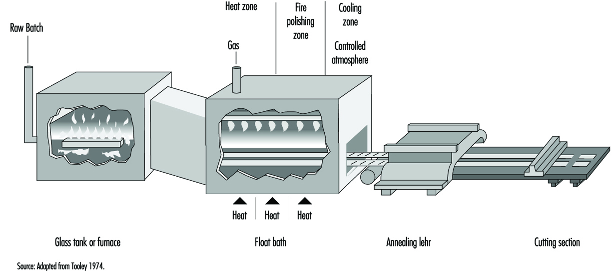
In the float process, a continuous ribbon of glass moves out of a melting furnace and floats along the surface of a bath of molten tin. The glass conforms to the perfect surface of the molten tin. On its passage over the tin, the temperature is reduced until the glass is sufficiently hard to be fed onto the rollers of the annealing lehr without marking its under surface. An inert atmosphere in the bath prevents oxidation of the tin. The glass, after annealing, requires no further treatment and can be further processed by automatic cutting and packing (see figure 8).
Figure 8. Ribbon of float glass exiting from lehr
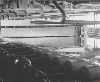
The trend in new residential and commercial architecture toward the inclusion of more glazing area, and the need to reduce energy consumption, has put increased emphasis on improving the energy efficiency of windows. Thin films deposited at the surface of the glass provide low emissivity or solar control properties. The commercialization of such commodity-coated products requires a low cost, large area deposition technology. As a result, an increasing number of float glass manufacturing lines are equipped with sophisticated on-line coating processes.
In commonly used chemical vapour deposition (CVD) processes, a complex gas mixture is brought into contact with the hot substrate, where it pyrolytically reacts to form a coating at the surface of the glass. In general, the coating equipment consists of thermally controlled structures which are suspended over the width of the glass ribbon. They may be located in the tin bath, the lehr gap or the lehr. The function of the coaters is to uniformly deliver the precursor gases over the ribbon width in a temperature-controlled fashion and to safely extract the exhaust gas by-products from the deposition region. For multiple coating stacks, multiple coaters are used in series along the glass ribbon.
For the treatment of the exhaust gas by-products generated by such large-scale processes, wet scrubbing techniques with a conventional filter press are normally sufficient. When the effluent gases are not easily reacted or wetted by aqueous solutions, incineration is the primary option.
Some optical glasses are chemically strengthened by processes which involve immersing the glass for several hours in high-temperature baths containing molten salts of, typically, lithium nitrate and potassium nitrate.
Safety glass is of two major types:
- Toughened glass is made by pre-stressing by heating and then rapidly cooling pieces of flat glass of desired shape and size in special ovens.
- Laminated glass is formed by bonding a sheet of plastic (usually polyvinyl butyral) between two thin sheets of flat glass.
Synthetic Vitreous Fibres
General profile
Synthetic vitreous fibres are produced from a wide variety of materials. They are amorphous silicates manufactured from glass, rock, slag or other minerals. The fibres produced are both continuous and discontinuous fibres. In general, the continuous fibres are glass fibres drawn through nozzles and used to reinforce other materials, such as plastics, to produce composite materials with unique properties. The discontinuous fibres (generally known as wools) are used for many purposes, most commonly for thermal and acoustical insulation. Synthetic vitreous fibres, for purposes of this discussion, have been divided into continuous glass fibres, with the insulation wools made of glass, rock or slag fibres, and refractory ceramic fibres, which are generally aluminium silicates.
The possibility of drawing heat-softened glass into fine fibres was known to glass makers in antiquity and is actually older than the technique of glass blowing. Many early Egyptian vessels were made by winding coarse glass fibres onto a suitably shaped mandrel of clay, then heating the assembly until the glass fibres flowed into one another and, after cooling, removing the clay core. Even after the advent of glass blowing in the 1st century AD, the glass fibre technique was still employed. Venetian glassmakers in the 16th and 17th centuries used it for decorating glassware. In this case, bundles of opaque white fibres were wound onto the surface of a plain transparent blown glass vessel (e.g., a goblet) and then fused into it by heating.
Despite the long history of generally decorative or artistic uses of glass fibres, widespread use did not arise again until the 20th century. Initial commercial US production of glass fibres occurred in the 1930s, while in Europe the initial use occurred some years earlier. Rock and slag wools were produced several years earlier than that.
The manufacture and use of synthetic vitreous fibres is a global multi-billion-dollar industry since these useful materials have become an important component of modern society. Their uses as insulations have resulted in tremendous reduction in energy requirements for heating and cooling buildings, and this energy savings has resulted in significant reduction in global pollution associated with energy production. The number of applications of continuous glass filaments as reinforcements for a plethora of products, from sporting goods to computer chips to aerospace applications, has been estimated to be in excess of 30,000. The development and widespread commercialization of refractory ceramic fibres occurred in the 1970s, and these fibres continue to play an important role in protecting workers and equipment in a variety of high-temperature manufacturing processes.
Manufacturing processes
Continuous glass filaments
Glass filaments are formed by drawing the molten glass through precious-metal bushings into fine filaments of nearly uniform diameter. Due to the physical requirements for the fibres when used as reinforcements, their diameters are relatively large compared to those in the insulation wools. Almost all continuous glass filaments have diameters of 5 to 15 μm or greater. These large diameters, coupled with the narrow range of diameters produced during the manufacture, eliminate any potential chronic respiratory effects, as the fibres are too large to be inhaled into the lower respiratory tract.
Continuous glass fibres are made by the rapid attenuation of drops of molten glass exuding through nozzles under gravity and suspended from them. The dynamic balance between the forces of surface tension and mechanical attenuation results in the drop of glass taking on the shape of a meniscus held at the annular opening of the nozzle and tapering to the diameter of the fibre being drawn. For fibre drawing to be successful, the glass has to be within a narrow range of viscosities (i.e., between 500 and 1,000 poise). At lower viscosities, the glass is too fluid and falls away from the nozzles as drops; in this case surface tension dominates. At higher viscosities, the tension in the fibre during attenuation is too high. The rate of flow of glass through the nozzle can also become too low to maintain a meniscus.
The function of the bushing is to provide a plate containing several hundred nozzles at a uniform temperature and to condition the glass to this uniform temperature so that the fibres drawn are of uniform diameter. Figure 9 shows a schematic diagram of the principal features of a direct-melt bushing attached to a forehearth from which it takes a supply of molten glass very near the temperature at which the glass will pass through the nozzles; in this case, therefore, the basic function of the bushing is also its sole function.
Figure 9. Schematic of direct-melt bushing
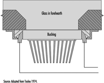
In the case of a bushing operating from marbles, a second function is required—namely, to first melt the marbles before conditioning the glass to the correct fibre-drawing temperature. A typical marble bushing is shown in figure 10. The broken line within the bushing is a perforated plate which retains the unmelted marbles.
Figure 10. Schematic of a marble bushing
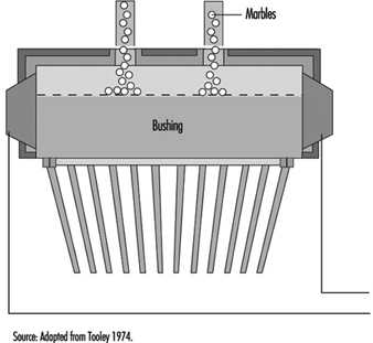
The design of bushings is largely empirical. For reasons of resistance to attack by molten glass and stability at the temperatures needed for fibre drawing, bushings are made from platinum alloys; both 10% rhodium-platinum and 20% rhodium-platinum are used, the latter being more resistant to distortion at elevated temperatures.
Before the individual fibres being drawn from a bushing are gathered and consolidated into a strand, or a multiplicity of strands, they are coated with a fibre size. These fibre sizes are basically of two types:
- starch-oil sizes usually applied to fibres intended for weaving into fine fabrics or similar operations
- keying agent plus film-former sizes applied to fibres intended for the direct reinforcement of plastics and rubber.
After the fibre is formed, a protective coating of organic sizing is applied at an applicator and the continuous filaments are gathered into a multifilament strand (see figure 11) before being wrapped on a winding tube. Applicators function by allowing the fan of fibres, when about 25 to 45 mm wide and on their way to the gathering shoe below the applicator, to pass over a moving surface covered with a film of fibre size.
Figure 11. Textile glass filaments
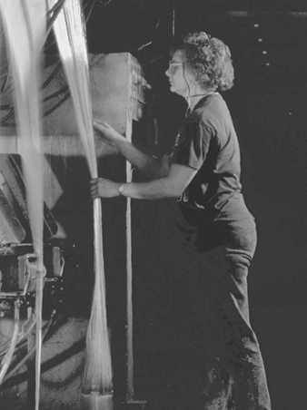
There are basically two types of applications:
- roller applicators, made of rubber, ceramic or graphite, in which the fibre runs over the surface of the roller coated with a film of fibre size
- belt applicators, in which at one end the belt passes over a driven roller which dips the belt into the fibre size and at the other end passes over a fixed hard chrome steel bar at which position the fibres touch the belt to pick up the size.
The protective coating and the fibre-gathering process can vary depending on the types of textile or reinforcement fibre being produced. The basic objective is to coat the fibres with size, gather them into a strand and locate them on a removable tube on the collet with the minimum necessary tension.
Figure 12 shows the process of continuous glass manufacturing.
Figure 12. Continuous filament glass manufacturing
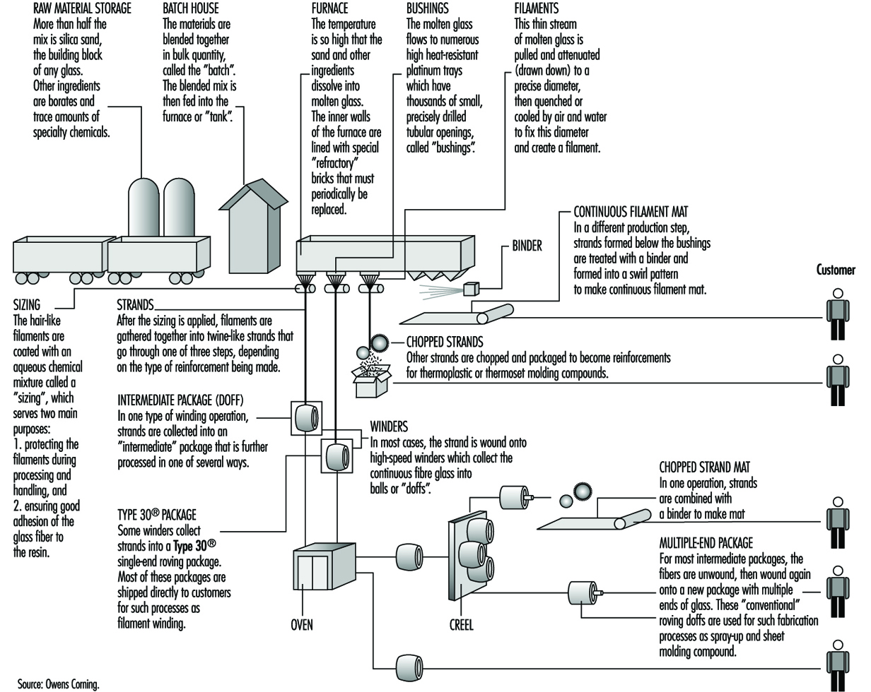
Insulation wool manufacturing
In contrast to continuous filaments, the fibres of the insulation wools and refractory ceramic fibres are made in very high energy processes in which molten material is dropped into either spinning discs or a series of rotating wheels. These methods result in the production of fibres with a range of diameters much wider than seen with continuous filaments. Thus, all of the insulation wools and ceramic fibres contain a fraction of the fibres with diameters of less than 3.0 μm; these could become respirable if fractured into relatively short lengths (less than 200 to 250 μm). Extensive data are available on exposures to respirable synthetic vitreous fibres in the workplace.
Several processes are used to manufacture glass wool, including the steam blowing process and flame blown process; but the most popular is the rotary forming process developed in the mid-1950s. The rotary processes have largely replaced direct blowing processes for the commercial production of glass-fibre insulation products. These rotary processes all employ a hollow drum, or spinner, mounted with its axis vertical. The vertical wall of the spinner is perforated with several thousand holes uniformly distributed around the circumference. Molten glass is allowed to fall at a controlled rate into the centre of the spinner, from where some suitable distributor forces it to the inside of the vertical perforated wall. From that position, centrifugal force drives the glass radially outwards in the form of discrete glass filaments issuing from every perforation. Further attenuation of these primary filaments is achieved by a suitable blowing fluid emerging from a nozzle or nozzles arranged around and concentric with the spinner. The net result is the production of fibres with a mean fibre diameter of 6 to 7 mm. The blowing fluid acts in a downwards direction and so, as well as providing the final attenuation, it also deflects the fibres towards a collecting surface situated below the spinner. On the way to this collecting surface, the fibres are sprayed with a suitable binder before being uniformly distributed across the collecting surface (see figure 13).
Figure 13. The rotary process for making glass wool
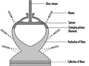
In a rotary process, glass wool fibres are made by allowing molten glass to run through a series of small openings which are situated in a revolving spinner and then attenuating the primary filament by air or steam blowing.
Mineral wool, however, cannot be produced on the rotary spinner process and historically has been produced in process with a series of horizontal spinning mandrels. The mineral wool process consists of a set of rotors (mandrels) mounted in a cascade formation and rotating very rapidly (see figure 14). A stream of molten stone is continuously transferred to one of the upper rotors and from this rotor distributed on the second and so on. The melt is uniformly spread on the outside surface of all the rotors. From the rotors, droplets are thrown out by centrifugal force. The droplets are attached to the rotor surface by elongated necks which, under further elongation and simultaneous cooling, develop into fibres. The elongation is, of course, followed by a decrease in diameter which, in turn, causes an accelerated cooling. Thus, there is a lower limit for the diameter among fibres produced in this process. A normal distribution of fibre diameters around the mean value is, therefore, not expected.
Figure 14. Mineral wool process (rock & slag)
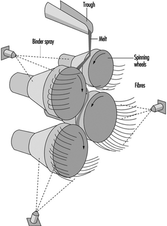
Refractory ceramic fibres
Ceramic fibres are primarily produced by blowing and spinning with methods similar to those described for the insulation wools. In the steam blowing process, raw materials such as alumina and silica are fused in an electric furnace, and the molten material is drawn off and blown with either pressurized steam or other hot gas. The fibres produced are then collected on a screen.
Similar to the spinning process for rock and slag fibres, those for ceramic fibres produce a high proportion of long silky fibres. In this method, a stream of molten material is dropped onto rapidly spinning discs and thrown off tangentially to form fibres.
Pottery Industry
General profile
The making of pottery is one of the oldest of human crafts. Over the centuries different styles and techniques have developed in different parts of the world. In the 18th century, a flourishing industry in many parts of Europe was strongly influenced by the import of fine and highly decorated ware from the Far East. Japan had learned the ceramic art from China about 400 years earlier. With the Industrial Revolution and the general change in conditions in Western Europe, production grew rapidly. At present, almost every country manufactures some ware for domestic use, and pottery is an important export from some countries. Production is now on a factory scale in many parts of the world. While the basic principles of manufacture have not changed, there has been considerable progress in the way in which manufacturing is carried out. This is particularly so in the forming or shaping of ware, in its firing and in the decoration techniques used. The increasing use of microprocessors and robots results in the introduction of high levels of automation in production areas. However, there also still exist everywhere many small-scale craft potteries.
Methods of forming
The earliest method of making pottery involved the hand method of building. Coils of clay are wound around, one on top of the other, and stuck together by pressing with the hands. The clay is first made into a soft state by working it with water. The object is then shaped and moulded by hand, once the coils are adhered.
The potter’s wheel has become a tool for creating pottery. With this method of forming, a pile of clay is placed on a revolving circular plate and is shaped by the wet hands of the potter. The water keeps the potter’s hands from sticking to the clay and keeps the clay moist and workable. Handles, spouts and other protrusions from the spinning clay are placed on just before the object is fired.
Casting is often used today when pottery of a high quality is desired and when the walls of the vessel are to be very thin. A mixture of clay and water, called slip, is poured into a plaster-of-Paris mould. The plaster absorbs the water, causing a thin coat of clay to be deposited all around the inside of the mould. When the deposit of clay is thick enough to form the walls of the vase, the rest of the slip is poured out, leaving the wet piece of ware on the inside of the form. As this dries it shrinks somewhat and can be removed from the mould. Usually the moulds are so constructed that they can be taken apart.
When the piece becomes thoroughly dry, it is smoothed and prepared for the firing process. It is placed in a fire-clay box called a sagger, which protects the piece from the flames and gases that are emitted during the process, just as an oven would protect a loaf of bread that is being baked. The saggers are placed one on top of another in a kiln. The kiln is a large structure that is built of fire brick and is surrounded by flues so that the flames of the fire may totally surround the dishes yet never actually come in contact with them. Smoke would discolour the pieces if they were not protected in such a manner.
Most pieces are fired at least twice. The first time through the kiln is called the bisque firing, and the piece of pottery is called a biscuit or bisque piece. After firing, the biscuit ware is glazed. A glaze is a glassy, glossy coating that makes the pottery more attractive and serviceable. Glazes contain silica, a flux to lower the melting temperature (lead, barium and so on) and metal oxides as colourants. When the glaze is applied to the pottery and is completely dry, it is again placed back into the kiln and is fired at such a high temperature that the glaze melts and covers the entire surface of the pottery.
Kinds of pottery
- Stoneware is a pottery made from either light or dark clay. It is glazed on the unburned body either before setting in the kiln or by means of salt during the burning process and is burned to a dense, hard condition.
- Porcelain is a white, vitrified ware. It is translucent. In porcelain, the body and glaze are brought to completion and maturity at one and the same burning, which takes place at a very high temperature.
- China is a ware similar to porcelain. The body and glaze are brought to completion and maturity at the same firing, at extremely high temperatures.
- Bone china is a variety of china in which burned bone is used as an ingredient, constituting about 40% of the mass.
- Earthenware has a white or nearly white body. It is produced by two firings, like china, but its body remains porous. The glaze is similar to that of china but is made of a cheaper material.
- Faience is a fine glazed earthenware used for ornamental and decorative purposes. Usually there is no attempt to produce a white body, and the glazes are frequently coloured.
Manufacturing processes
The physical properties of pottery vary according to the composition of the body and conditions of firing. The body for any particular use is selected mainly for its physical properties, but white bodies are most usually chosen for tableware.
Industrial products (e.g., refractories, electrical insulators, catalyst carriers and so on) have a wide range of properties according to their eventual use.
Raw materials. The basic ingredients in a pottery body are shown in table 1, which also indicates typical proportions in sample body types.
Table 1. Typical body constituents (%)
|
Body |
Plastic Base |
Flux |
Filler |
|||||
|
Ball Clay |
Kaolin |
Stoneware clay |
Stone |
Feldspar |
Quartz |
Bone ash |
Other |
|
|
Earthenware |
25 |
25 |
15 |
35 |
||||
|
Stoneware |
30–40 |
25–35 |
20–25 |
20–30 (grog) |
||||
|
China |
20–25 |
20–25 |
15–25 |
25–30 |
||||
|
Porcelain |
40–50 |
20–30 |
15–25 |
|||||
|
Bone China |
20–25 |
25–30 |
45–50 |
|||||
Nepheline-syenite is sometimes used as flux, and alumina can replace some or all of the quartz filler in some porcelain-type bodies. Cristobalite (calcined sand) is used as a filler in some pottery bodies, particularly in the wall tile industry.
The body composition is determined partly by the required properties of the end product and partly by the production method. A plastic base is essential for ware that is shaped while moist, but not for non-plastic forming processes, such as dust pressing. The plastic base is not essential, although clay is still the principal ingredient in most ceramic products, including those prepared by dust pressing.
Industrial ceramics are not shown in table 1, as their composition ranges from all ball clay or fireclay, without additional flux or filler, to almost all alumina, with a minimal amount of clay and no added flux.
During firing, the flux melts to a glass to bind the ingredients together. As the amount of flux increases, the temperature of vitrification is lowered. Fillers influence the mechanical strength of the clayware before and during firing; in making tableware, quartz (as sand or calcined flint) is traditionally used, except that bone ash is used in making bone china. The use of alumina or other non-siliceous fillers, which are already employed in the manufacture of industrial ceramics, is being extended to the making of other ware, including domestic products.
Processing. The basic processes in the production of pottery include:
- preparation of the body ingredients
- forming and shaping
- biscuit firing
- application of glaze
- glost firing
- decoration.
The preparatory processes of calcining, crushing and grinding of flint or stone may be done in a separate establishment, but it is usual for all subsequent processes to be carried on in the same factory. In the slip house, the body ingredients are blended in water; plastic clay is then produced by filtering and plugging; the casting slip is then prepared by blunging to a creamy consistency. Dust for pressing is prepared by drying and grinding.
Traditional classifications of shaping processes are shown in table 2. In casting, a water suspension of the body is poured into an absorbent mould and the cast is removed after partial drying. Plastic clay shaping by throwing is now rare in industrial production; mechanical spreading over or in a plaster mould (jiggering and jolly) with separation from the mould after drying is almost universal in making tableware. Pressing of plastic clay or extrusion is mainly restricted to industrial ceramics. Dust-pressed articles are produced by compacting pre-dried body-dust by hand or mechanical pressing.
Table 2. Manufacturing processes
|
Products |
Usual processes |
|
Tables |
Plastic clay shaping; casting |
|
Sanitary ware |
Casting |
|
Tiles |
Dust pressing (wall or vitrified floor tiles), plastic clay pressing (floor quarries) |
|
Industrial ware |
Dust pressing, plastic clay pressing |
After shaping, the ware may be dried and finished by fettling, towing or sponging. Then it is ready for biscuit firing.
After biscuit firing, glaze is applied by dipping or spraying; dipping may be by hand or mechanized. The glazed ware is then fired again. Sometimes, as with sanitary whiteware, glaze is applied to the dried clay article and there is only one firing.
Decoration may be applied either under or over glaze and may be by hand painting, machine printing or transfer; over-glaze decoration involves a third firing; and sometimes separate firings for different colours are necessary.
In the final stages, the ware is sorted and packed for shipping. Figure 15 identifies the various paths followed by various types of pottery and ceramics during their fabrication.
Figure 15. Flow chart by type of ceramic
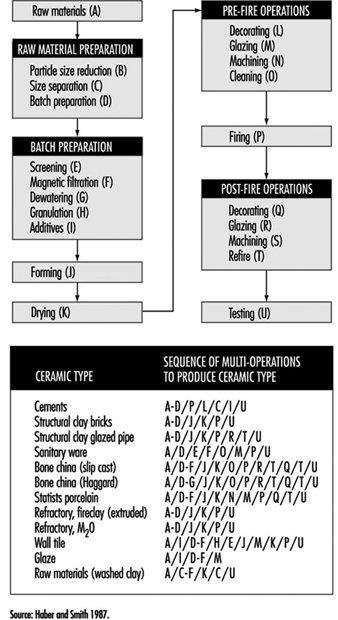
Ceramic Tile
General profile
Ceramic is a term once thought to refer only to the art or technique of producing articles of pottery. The etymology of the term shows that it derives from the Greek keramos, meaning “a potter” or “a pottery”. However, the Greek word is related to an older Sanskrit root, meaning “to burn”; as used by the Greeks themselves, its primary meaning was simply “burnt stuff” or “burnt earth”. The fundamental concept contained in the term was that of a product obtained through the action of fire upon earthy materials.
A traditional ceramic, in the context of this article, refers to the products commonly used as building materials or within the home and industry. Although there is a tendency to equate traditional ceramics with low technology, advanced manufacturing technologies are often used in this industry. Stiff competition among producers has caused the technology to become more efficient and cost effective by utilizing complex tooling and machinery, coupled with computer-assisted process control.
The oldest ceramic products originated from clay-bearing materials. Early potters found the plastic nature of clay to be useful in forming shapes. Because of its tendency to exhibit a large amount of shrinkage, clay bodies were modified by adding coarse sand and stone, which reduced shrinkage and cracking. In modern clay-based bodies, the typical non-clay additions are silica flour and alkali minerals that are added as fluxes. In traditional ceramic formulations, clay acts as a plasticizer and binder for other constituents.
Development of the industry
The production of dried and fired clay tiles has very ancient origins dating back to Middle Eastern populations. The tile whiteware industry developed significantly in Europe, and by the beginning of the 20th century floor and wall tile production achieved industrial scale. Further development in this field occurred after the Second World War. Europe (Italy and Spain, in particular), Latin America and the Far East are now the most important areas of industrial tile production.
The floor and wall tile sector of the whiteware industry has seen a great deal of development since the mid-1980s with the introduction of new technologies, automation and integration of production flow into the manufacturing process. Subsequently, productivity and efficiency increased, while energy consumption and costs have been reduced. Tile manufacturing is now continuous in both wet and dry tile production, and many plants today have nearly 100% automation. The major innovations in the tile industry during the last decade include wet grinding, spray drying, high-pressure dry pressing, roller drying and fast-firing technologies.
The value of the US ceramic tile market supply (US factory shipments plus imports) increased an estimated 9.2% compounded annually between 1992 and 1994. Dollar sales were estimated to have reached US$1.3 billion in 1994. At the same time, volume sales rose 11.9% compounded annually to 1.3 billion square feet. This compares with a market growth rate of 7.6% based on dollar sales, and 6.9% based on volume sales between 1982 and 1992.
Classifications of ceramic tiles
Redware and whiteware
Many types of ceramic tile are available on the market. They differ according to the condition of the surface, colour of the body (white or red), manufacturing technology, raw materials and end use. The difference between “red” and “white” tiles lies in the amount of iron minerals contained in the body. By reacting with the other body components, they can give more or less colouration and modify the behaviour of the body during firing.
A complete and exhaustive classification is very difficult owing to the extreme heterogeneity of the tile products, their processing and subsequent characteristics. In this chapter, European (EN) and ASTM standards are considered.
EN standards exclusively classify ceramic tiles as a function of water absorption (which directly correlates to the porosity) and shaping method (extrusion or pressing). The shaping methods are classified as:
- shaping process A (extruded floor tiles). This process includes split tiles and individually extruded tiles.
- shaping process B (dry-pressed floor and wall tiles).
European Standard EN 87, approved in November 1981, specifies that “Ceramic wall and floor tiles are building materials that are generally designed for use as floor and wall coverings, both indoors and outdoors, regardless of shape and sizes”.
The American National Standards Institute (ANSI) specification for ceramics tile (ANSI A 137.1) contains the following definitions:
- Ceramic mosaic tile is formed by either the dust-pressed or plastic method, usually 6.4 to 9.5 mm (1/4 to 1/8 in.) thick, and has a facial area of less than 39 cm2 (6 in2 ). Ceramic mosaic tiles may be either porcelain or natural clay composition, and they may be either plain or with an abrasive mixture throughout.
- Decorative wall tile is glazed tile with a thin body that is usually non-vitreous and suitable for interior decorative residential wall use where breaking strength is not a requirement.
- Paver tile is glazed or unglazed porcelain or natural clay tile formed by the dust-pressed method having 39 cm2 (6 in2 ) or more facial area.
- Porcelain tile is ceramic mosaic tile or paver tile that is generally made by the dust-pressed method with the resulting tile composition that is dense, impervious, fine-grained and smooth, with a sharply formed face.
- Quarry tile is glazed or unglazed tile, made by the extrusion process from natural clay or shale, usually having 39 cm2 (6 in2) or more facial area.
- Wall tile is glazed tile with a body that is suitable for interior use and usually non-vitreous and is not required to withstand excessive impact or be subject to freezing and thawing conditions.
- Individual tile whiteware grades include unglazed tiles (ceramic mosaic tile, quarry tile, paver tile) and glazed tiles (glazed wall tile, glazed ceramic mosaic tile, glazed quarry tile, glazed paver tile) (ANSI 1988).
The tiles are manufactured by standard ceramic processes. Ceramic wall and floor tiles are prepared from a mixture of ball clays, sand, fluxes, colouring agents and other mineral raw materials, and they undergo processing such as milling, screening, blending and wetting. They are shaped by a pressing, extrusion, casting or other process, normally at room temperature, and are subsequently dried and finally fired at high temperature. Tiles may be glazed, unglazed or engobed. Glazes are glasslike, impervious coatings, and engobes are matte, clay-based coatings that may also be porous. Glazed wall and floor tiles are produced either by single-or two-stage firing.
Traditional ceramic bodies are formed into shapes using many different techniques. The specific forming process is dictated by numerous factors, including material characteristics, size and shape of the part, part specifications, production yield and accepted practices within the geographic region.
Clay-based bodies are heterogeneous mixtures of one or more clays and one or more nonclay powders. Before attaining a final shape, these powders undergo a sequence of unit operations, firing and post-fire operations (see figure 17).
For most traditional bodies, forming techniques can be classified as soft plastic forming, stiff plastic forming, pressing and casting.
Applied pressure is employed to rearrange and redistribute the raw materials into a better-packed configuration. The rheological behaviour of clay-based bodies results from clay mineral inter-action with water, which imparts plasticity to the batch. In nonclay bodies, this same type of behaviour can be achieved by adding plasticizers.
Industrial Ceramics
General profile
Ceramics differ from other engineering materials (metals, plastics, wood products, textiles) in a number of individual properties. Perhaps the most distinctive difference to a designer or potential user of ceramic ware is the unique shape and size of each individual ceramic piece. Ceramics are not readily shaped or worked after firing, except by very costly grinding; consequently, they normally must be used as is. Except for some simple tile, rod and tube shapes of limited sizes, ceramics cannot be marketed by the foot or by the yard, nor cut to fit on the job.
All the useful properties, including shape and size, must be provided in advance, beginning with the very early stages of ceramic processing. The structural integrity of each piece must be preserved through a variety of thermal and mechanical stress exposures during processing and until the piece is finally installed and in service. If a ceramic should fail in service as a result of a variety of causes (brittle fracture on impact, thermal shock, dielectric breakdown, abrasion or melting slag corrosion), it is not likely to be repairable, and usually must be replaced.
Significant advances have been made in fundamental understanding and technological control of the properties of ceramics, and of their utilization in many new, demanding, highly technical applications. The industry in general, and the technical and electronic ceramic portions of it in particular, have devised production and control techniques for mass producing complex shapes in bodies having carefully controlled electrical, magnetic and/or mechanical properties while maintaining dimensional tolerances that are good enough to permit relatively easy assembly with other components.
Many ceramics are produced in large volume as standard items. Refractory bricks and shapes, crucibles, muffles, furnace tubes, insulators, thermocouple protection tubes, capacitor dielectrics, hermetic seals and fibre boards are routinely stocked by a number of ceramic producers in a variety of compositions and sizes. It is usually quicker and cheaper to use stock items whenever possible. When stock items will not meet the need, most manufacturers are prepared to custom produce items. The more stringent the requirements for a given property of the ceramic, or the more restrictive the requirements for specific combinations of properties, sizes and shapes, the more limited are the accepted compositional, microstructural and configurational parameters for the ceramic. Hence the cost and difficulty of manufacture are greater. Most ceramic manufacturers have experienced staff engineers and designers who are well qualified to work with potential customers on details of ceramic ware design.
Markets
The major market for state-of-the-art ceramics has been and will continue to be in electronics, but vigorous worldwide research and development programmes are continuously searching for new applications and identifying ways of improving ceramic properties such that new markets can be accessed.
Advanced ceramics are produced in Japan, the United States and Western Europe. The raw materials used in the industry are traded on an international basis, principally as powders, but there is also a significant amount of in-house processing.
The major applications of industrial ceramics are:
- Oxides. The main oxide materials in use today are alumina in spark plugs, substrates and wear applications; zirconia (ZrO2) in oxygen sensors, as a component in lead-zirconium-titanate (PZT) piezoelectrics, wear applications and thermal barrier coatings; titanates in barium titanate capacitors and PZT piezoelectrics; and ferrites in permanent magnets, magnetic recording heads, memory devices, temperature sensors and electric motor parts.
- Carbides and nitrides. Carbides (mainly silicon carbide and boron carbide) are used in wear applications, while nitrides (mainly silicon nitride and Sialon) are used in wear applications and cutting tools. Aluminium nitride, with its high thermal conductivity, is the primary contending material for part of the electronics substrate market currently dominated by alumina.
- Mixed oxide ceramics. Ceramics research and development efforts are focused on a number of new applications for ceramics that all have enormous potential. Three significant applications are: (1) ceramic superconductors, (2) ceramics for solid oxide fuel cells and (3) ceramic components for heat engines.
Ceramic superconductors are based on a number of mixed oxide systems that include yttrium, barium, copper, strontium and copper (YBa2Cu3O7-8, Bi2Sr2CaCu2O8, Bi2Sr2Ca2Cu3O10) stabilized with lead oxide. Solid oxide fuel-cell ceramics are based on ionic conductors in which high-purity stabilized zirconia is currently the material of choice. Ceramic heat-engine components under investigation are composed of silicon carbide, Sialons and zirconia, either as single-phase ceramics, ceramic-ceramic composites or metal-matrix composites (MMCs).
Manufacturing processes
Manufacturing technology development
Processing innovations. Research and development activity is generating new technologies for the production of ceramic materials. Precursor-derived ceramics were estimated to have a market value of US$2 million in 1989, the major part of which was in CVD (86% of the total market value). Other segments of this growing market include chemical vapour infiltration (CVI), sol-gel and polymer pyrolysis. Products that are being successfully produced by these means include continuous ceramic fibres, composites, membranes and ultra-high-purity/high-activity powders.
The processes used to convert these raw materials to finished products include additional powder processing (e.g., milling and spray drying) prior to forming green shapes that are then fired under controlled conditions. The forming processes include die pressing, isostatic pressing, slip casting, tape casting, extrusion, injection moulding, hot pressing, hot isostatic pressing (HIP), CVD and so on.
Chemical additives to aid ceramic processing. Each step in the manufacturing process requires careful control so that end-product properties are obtained at maximum production efficiency and key effect chemicals are used to optimize powder treatment and green forming. The effect chemicals include milling aids, flocculants and binders, lubricants to effect product release during pressing and minimize wear of die parts, and plasticizers to aid extrusion and injection moulding. A list of such chemicals is shown in table 3. While these materials play an important economic role in production, they are burnt out during firing and play no part in the final product chemistry. The burn out process has to be carefully controlled to avoid residual carbon in the finished products, and process research and development is continuously investigating ways of minimizing the levels of effect chemicals used.
Table 3. Selected chemical additives used to optimize powder treatment and green forming of ceramics
|
Material |
Application or function |
|
Polyvinyl alcohol |
Binder for advanced ceramics |
|
Polyethylene glycol |
Binder for advanced ceramics |
|
Sodium polyacrylate |
Deflocculant for slip casting |
|
Tertiary amide polymer |
Binder for dry pressing |
|
Starch blended with dry colloidal aluminosilicate |
Binder for vacuum forming |
|
Cationic alumina plus organic flocculant |
Binder for vacuum forming |
|
Pre-gelled, cationic corn starch |
Flocculant for colloidal silica and alumina binder |
|
High-purity sodium carboxymethylcellulose |
Binder |
|
Inorganic colloidal magnesium aluminium silicate |
Suspending agent |
|
Medium-viscosity sodium carboxymethylcellulose added to Veegum |
Suspending agent, viscosity stabilizer |
|
Ammonium polyelectrolyte |
Dispersing agent for casting slips for electronic ceramics |
|
Sodium polyelectrolyte |
Dispersing agent binder for spray-dried bodies |
|
Microcrystalline cellulose and sodium carboxymethylcellulose |
Thickening agent |
|
Polysilazane |
Processing aid, binder and precursor for advanced ceramics |
In addition to spawning ceramic products and ceramic manufacturing technologies for new applications, the influence of the advanced ceramics industry on the traditional ceramics industry should not be overlooked. It is expected that many high-technology materials and processes will find application in the traditional ceramics industry as the latter strives to reduce manufacturing costs, to improve quality and to give better value in service to the end user.
Raw materials
There are certain key materials that are either used directly by the ceramics industry or that represent the starting point for the production of added-value materials:
- silica
- clay
- alumina
- magnesia
- titania
- iron oxide
- zircon/zirconia.
This discussion will focus on the properties of silica, alumina and zircon/zirconia.
Silica, in addition to its use in refractories and whitewares, is also the starting point in the manufacture of elemental silicon, silicon carbide and silicon tetrachloride. Silicon, in turn, is the starting point for silicon nitride, and silicon tetrachloride is the precursor for a wide range of silicon organics that can be pyrolyzed under controlled conditions to high-quality silicon carbide and silicon nitride.
Silicon nitride and its Sialon derivatives, as well as silicon carbide, despite their tendency to oxidize, have the potential to meet many of the property targets set by the heat-engine market. A feature of silica and the ceramic materials that are derived from silica is that all the elements are readily available in the earth’s crust. In this respect, these materials offer the potential of ease of supply in all parts of the world. In practice, however, there is a significant energy input required to produce silicon and silicon carbide. Consequently, manufacture of these materials is by and large limited to countries with cheap and readily available electric power.
Alumina is found throughout the earth’s crust as a component in aluminosilicate minerals. Economics dictate that alumina be extracted from bauxite using the Bayer process. Bauxite is widespread in the equatorial belt in different states of purity, and is divided into two classifications: refractory grade ore and metallurgical ore.
Refractory grade bauxite is supplied by China and Guyana as a high-temperature calcine of the naturally occurring mineral: diaspore (Al2O3·H2O) in China and gibbsite (Al2O3·3H2O) in Guyana. During calcination, a complex phase assemblence of corundum (Al2O3), mullite, silica glass and minor levels of aluminium titanate is formed. The consumption of refractory grade bauxite exceeds 700,000 tonnes per year on a worldwide basis.
Metallurgical grade bauxite is mined in Australia, Jamaica and West Africa, and has variable alumina levels in conjunction with major impurities such as iron oxide and silica. The alumina in the metallurgical ores is extracted from the ore when dissolved by sodium hydroxide, yielding a sodium aluminate solution that is separated from the iron oxide and silica, which are rejected as a waste product in the form of red mud. Essentially, pure aluminium hydroxide is precipitated from the sodium aluminate and then calcined to a number of grades of alumina.
The high-purity aluminas used in the ceramics industry and derived by the Bayer process are classified as tabular alumina, fused alumina or speciality calcined alumina.
Tabular alumina is produced by high-temperature (~2,000°C or 3,630°F) calcination of low-temperature calcined alumina in large, oil-fired rotary kilns. Fused alumina is produced by the electric melting of calcined alumina. Tabular and fused alumina are sold to the refractory industry in crushed and graded form for use in a wide range of high-quality products, such as in continuous casting refractories (e.g., single-edge-notched or SEN/slide gates), monolithic refractories for application in blast furnaces and the petrochemical industry.
Speciality calcined alumina powders are the major raw materials used in the advanced ceramics industry for both electronic and engineering applications. The powders are produced in a wide range of grades according to exacting specifications of chemistry, particle size and crystal type, to suit a wide range of end-product applications.
There is an established international trade in high-quality aluminas. Many of the ceramic manufacturers have in-house milling and spray drying facilities. There is clearly a limitation to the growth in the supply of spray-dried systems and a continuing need to supply aluminas which match the customer plants so that use of the latter can be optimized at an acceptable price. Alumina is a significant ceramic material that is available at a high degree of purity. The dominant position of alumina as a ceramic raw material arises because it has desirable properties at a relatively low cost. This cost effectiveness is attributable to the commodity nature of the business arising from the large demand for alumina by the aluminium industry.
Zircon and zirconia. The primary source of zirconia is the mineral zircon (ZrO2 SiO2), which exists in beach sands principally in Australia, South Africa and the United States. Zircon extracted from beach sands contains about 2% hafnium oxide and traces of Al2O3 (0.5%), Fe2O3 (0.1%) and TiO2 (0.1%). In addition, all zircons contain traces of uranium and thorium. Zircon is processed by fine grinding to produce a range of milled products of defined particle size. These products have found use in investment casting, foundries, refractory products and as an opacifier in glazes for whitewares.
Zircon is also the principal source of zirconia. Zircon can be chlorinated in the presence of carbon to give zirconium and silicon tetrachlorides that are then separated by distillation. The zirconium tetrachloride produced can be used to prepare zirconia directly or as a feedstock for other zirconium chemicals. Sintering with alkali or alkaline earth oxides is also used to decompose zircon. Silica is leached from the decomposition products with water, leaving zirconium hydroxide to be further purified by acid dissolution and reprecipitation. Zirconia is then obtained by calcining the hydroxide. Zircon is also converted to zirconia and silica in a plasma at 1,800°C (3,270°F) with rapid cooling to prevent reassociation. The free silica is removed by dissolution in sodium hydroxide. Fused zirconia is produced in electric arc furnaces from either baddeleyite or zircon/carbon feedstocks. In the latter process the silica component of zircon is carbothermally reduced to silicon monoxide, which volatilizes prior to the fusion of the residual zirconia.
Summary
The industrial ceramic industry is very diverse and there is much in-house processing. Many of the final manufacturing operations are in foundry-type atmospheres. The material-handling systems in these operations convey fine raw materials where dust can be an issue. Materials are then raised to very high temperatures and melted or fused into shapes needed for the final parts. Therefore, many of the safety issues which exist in any high-temperature industry also exist in the industrial ceramics industry.
Brick and Tile
General profile
Bricks and tiles made from clay have been used as building material since the earliest times in many parts of the world. When properly made and fired they are more durable than some stones, resistant to weather and great changes of temperature and moisture. The brick is a rectangle of standard size, varying slightly from region to region but essentially convenient for handling with one hand by a bricklayer; roofing tiles are thin slabs, either flat or curved; clay tiles may also be used for floors.
The brick industry is very fragmented. There are many small suppliers located all over the world. Brick manufacturing tends to involve local suppliers and local markets due to the cost of shipping of the finished product. In 1994, there were 218 brick manufacturing plants in the United States, and in 1992 the number of producers of structural clay products in the UK was listed at 182, for example. Brick manufacturers generally are located near the clay deposits to reduce raw material shipping cost.
In the United States, bricks are used primarily in residential construction as either a load-bearing material or as a facade material. Since the brick industry is so closely coupled to the housing industry, manufacturing activity is highly dependent on the residential construction industry and almost totally dependent on the combined residential and non-residential construction industry.
Manufacturing processes
Materials and processing
The basic material is clay of various kinds with mixtures of loams, shales and sand, according to local supply and needs, to give the required properties of texture, plasticity, regularity and shrinkage, and colour.
Extraction of clay is now often fully mechanized; manufacture usually takes place alongside the extraction hole, but in large works the clay is sometimes conveyed in skids on ropeways. The subsequent processing of the clay varies according to its constitution and the end-product, but in general includes crushing, grinding, screening and mixing. See figure 16 for a typical brick-manufacturing operation.
Figure 16. The manufacture of bricks & tiles
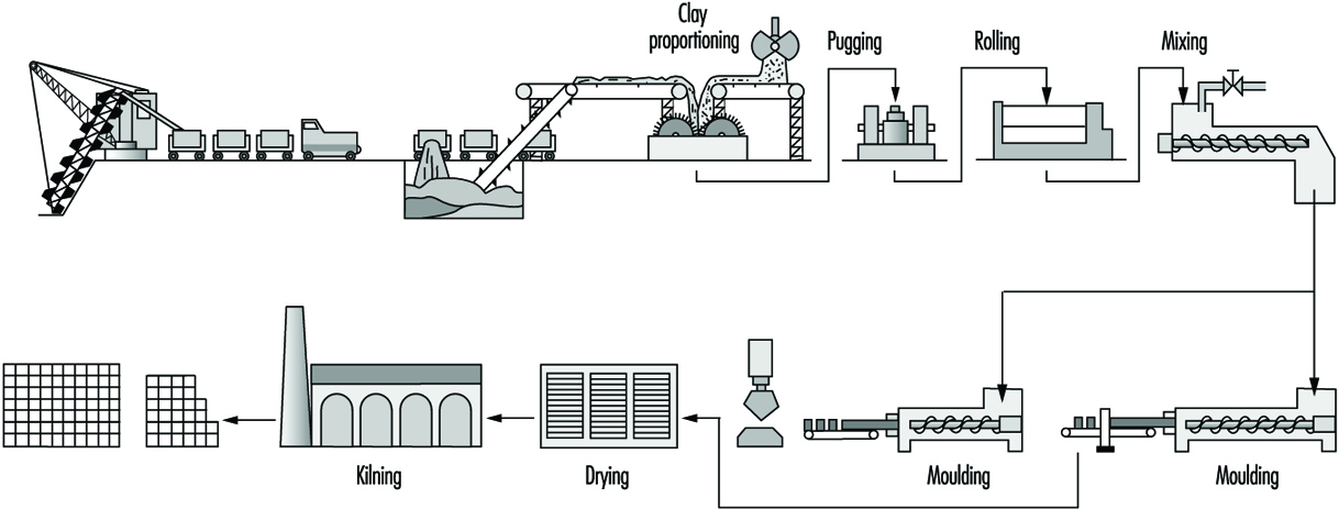
Clay for wire-cut bricks is broken up by rollers; water is added in a mixer; the mixture is rolled again and then fed through a horizontal pugmill. The plastic clay extruded is then cut to size on a wire-cutting table. Semi-dry and stiff plastic material is produced by rolling and screening and is then fed to mechanical presses. Some bricks are still hand moulded.
Where plastic material is used, the bricks have to be dried either by sun and air, or more frequently in regulated kilns, before firing; bricks made from semi-dry or stiff plastic may be fired immediately. Firing may take place in ring kilns, often hand fed, or in tunnel kilns, mechanically fed. The fuels used will vary according to local availability. A finishing glaze is applied to some decorative bricks.
Refractories
General profile
Refractory materials are traditionally thought of as non-metallics that resist degradation by corrosive gases, liquids or solids at elevated temperatures. These materials must withstand thermal shock caused by rapid heating or cooling, failure attributable to thermal stresses, mechanical fatigue due to other material contacting the refractory itself and chemical attack activated by the high-temperature environment. These materials are required for the manufacture of most ceramic products and are specifically needed in ovens, dryers, furnaces and high-temperature-bearing engine parts.
Refractories remained almost exclusively mineral-based until well into the 20th century. Yet technologists who were skilled in mineralogy were paying attention. Metallurgists had been experimenting with acid and basic slagging practices since the Middle Ages and had catalogued some of the benefits of each. Refractory artisans had correspondingly experimented with ganister, with other nearly pure silica minerals and with magnesite, a predominantly MgCO3 mineral which was calcined to MgO. When the Bessemer steel-making converter was invented in 1856, combining working temperatures of over 1,600ºC with corrosive acid slagging, “acid” silica refractories were all but ready. When the Siemens open hearth furnace followed in 1857 at even higher temperatures, and steel making went over in both cases to corrosive basic slagging, “basic” magnesite linings were soon introduced. Basic refractories made from dolomite (MgO-CaO) were developed during the First World War, when the European magnesite supply was cut off from the Allies. Later, with the development of other mineral resources worldwide, magnesite reasserted itself.
Table 4. Refractory usage by industry in the United States
|
Industry |
Percentage of total US sales |
|
Iron and steel |
51.6 |
|
Nonferrous metals |
7.5 |
|
Cement |
4.9 |
|
Glass |
5.1 |
|
Ceramics |
9.7 |
|
Chemical and petroleum |
2.1 |
|
Public utilities |
0.9 |
|
Export |
7.4 |
|
All other and unspecified |
10.8 |
Meanwhile, bonded carbon bricks were produced in the United Kingdom starting in 1863 and eventually found their way into the iron-smelting blast furnace as its working temperatures climbed still higher. They also went quickly into the Hall-Héroult cells for the production of aluminium (1886).
Lime had been made for some 5,000 years using clay and then firebrick kilns. Portland cement manufacturing first called for an innovative refractory when rotary kilns were introduced after 1877. The first resistant linings were made of cement-bonded cement clinker. Later on more durable commercial refractories returned to this industry.
Recuperative and regenerative furnaces, originating in the newborn manufacture of steel in the 1850s, were introduced into nonferrous metallurgy and glassmaking in the late 19th century. Fireclay refractories had to be superseded there, too. Magnesite linings were used in copper converters from 1909, and in the first modern glass tanks about 10 years later. Electric arc furnaces were first tried for steel making in 1853 and became common after 1990. A roughly 100-tonne unit installed in the United States in 1927 employed a magnesite lining.
Three-phase arc furnaces were in place before 1950; it was only then that serious demands arose for more sophisticated refractories. In the same time frame, oxygen blowing was introduced into Bessemer and open-hearth furnaces in the 1940s. The basic oxygen furnace (BOF) literally took over steel making in the late 1950s. Oxygen blowing, by its sheer economic importance, impelled the refractories industry for the first time to introduce synthetic materials into its products on a significant scale.
Properties of refractory materials
The properties that characterize quality refractory materials depend on the nature of the application. The most important aspect of the materials is referred to as “refractoriness”. This term refers to the point at which the specimen begins to soften (or melt). Typically, refractories do not have a specific melting point; the phase transition proceeds over a range of temperatures in a phenomenon called softening. This characteristic is often quantified with a pyrometic cone equivalent (PCE), which is a measure of heat content measured by the slumping of a cone during thermal cycling.
A related, and often more useful property, is the temperature of failure under load. Refractories often fail under load at temperatures much less than the temperature that corresponds to the PCE. In obtaining a value for this parameter, the refractory is subjected to a known load and is subsequently heated. The temperature at which sagging or general deformation occurs is reported. This is of great interest because the value is used to predict mechanical properties during use of the refractory. The load-bearing ability of refractory materials is directly proportional to the amount of viscosity of the glass present.Another factor that is essential to understanding the performance of a refractory is the dimensional stability. Throughout industrial use, refractory materials are subjected to heating/cooling cycles, which cause the refractory units to either expand or contract. Large changes in the dimensions will reduce stability and may ultimately lead to failure of the refractory-based structure.
A related phenomenon commonly observed with refractory materials is spalling. Spalling is generally considered fracture, splitting or flaking of the refractory, resulting in the exposure of the inner mass of the material. Spalling is usually brought about by temperature gradients within the material, compression in the structure due to large-volume charges and variations of the thermal expansion coefficient within the brick. Every effort is made in refractory manufacture to avoid spalling because it reduces the effectiveness of the refractory.
Refractories have application across a wide variety of industrial applications ranging from extensive use in the iron and steel industry to low volume usages in the cement and public utilities industries. Basically, refractories are used in any industry where high temperatures are used to heat and dry or incinerate material. Table 4 provides a current breakdown by industry of refractory usage within the United States.
As shown in table 4 the steel industry is the area where over 50% of the refractory produced in the U.S. is utilized. Therefore, the needs of the steel industry to a great extent have driven the refractory developments which have occurred.
Modern refractories
Ceramics had grown substantially from craft to applied science. The American Ceramic Society had been founded in 1899, the British Ceramic Society in 1901. Oxide phase diagrams began to appear in the literature in the 1920s. The techniques of petrography were well developed, and the detailed mechanisms of refractory degradation and wear were beginning to be understood. American refractory producers had become largely reorganized, consolidated and capable of performing their own research. The tools of refractory synthesis and instruments of investigation were both burgeoning.
Synthetic industrial carbons were, of course, not new. Coke was first made commercially from coal in the 1860s, and from petroleum shortly thereafter. Synthetic graphite and silicon carbide appeared almost simultaneously at the turn of the century, following Acheson’s invention of the self-resistance-heated electric furnace in 1896. These products, having properties quite unlike those of oxides, rapidly stimulated their own uses and markets.
Synthetic alumina, Al2O3, had been available since the Bayer process started feeding aluminium production about 1888. Synthetic magnesia (MgO) was first made from seawater in the United Kingdom in 1937 and in the United States in 1942, stimulated by wartime needs for magnesium. Zirconia had become available, also spurred by the military. Lime had been a major commodity for ages. A host of other chemicals were on hand for consideration as refractory components or as minor additives and bonding agents. The only important component of oxide refractories that for the most part has resisted replacement by synthetics is silica (SiO2) High-purity silica rocks and sands abound and are used in this industry as well as in glass formulation.
The use of synthetics in refractory manufacture has been enormously helpful; but mineral raw materials have by no means been displaced. Synthetics cost more, and that cost has to be justified. Some synthetic materials create severe problems in refractory processing, and new ways must be found to overcome these. Optimum results have often been achieved by combinations of synthetic and mineral raw materials, along with creative inputs into their processing.
Mixtures of clay with carbon had been used to line crucibles and ladles since iron was first poured; and silica bricks containing carbon were made in France in the 1860s. Since 1960 both the techniques and the compositions have changed dramatically. The use of carbon-bearing oxide refractories has mushroomed, starting with MgO+C. The first real impetus may have been provided by the BOF; but today there is hardly any advanced oxide refractory type that cannot be had either with or without added carbon or a carbon precursor for superior performance in specific applications.
Arc-fused refractory grain or aggregate had been made since the early 1900s, and fused-cast refractory bricks of several compositions followed in the twenties and thirties, notably of mullite, alumina, magnesia-alumina-silica and alumina-zirconia-silica. More often than not, these products were made entirely from mineral raw materials.
In fact, all-mineral-based refractories remain today an important component of the product menu. They are on the whole cheaper, they often perform admirably and there are still many applications of lesser demand as well as those of critical demand for the highest levels of refractoriness and corrosion resistance.
Refractory industry
Refractories will be found in use in many industries for lining boilers, kilns and furnaces of all kinds, but the largest percentage are used in manufacture of metals. In the steel industry, a typical blast or open-hearth furnace may use many different types of refractories, some made from silica, some from chrome and/or magnesite and others of fire clay.
Much smaller quantities are also used in the following industries: gas, coke and by-products; power-generating plants; chemicals; bake ovens and stoves; cement and lime; ceramics; glass; enamels and glazes; locomotives and ships; nuclear reactors; oil refineries; refuse disposal (incinerators).
Manufacturing processes
The type of refractory that is used in any particular application depends on the critical requirements of the process. For example, processes that demand resistance to gaseous or liquid corrosion require low porosity, high physical strength and abrasion resistance. Conditions that demand low thermal conductivity may require entirely different refractories. Indeed, combinations of several refractories are generally employed. There is no well-established line of demarcation between those materials that are and those that are not refractory, although the ability to withstand temperatures above 1,100°C without softening has been cited as a practical requirement of industrial refractory materials.
The technical goals of manufacture of a given refractory are embodied in its properties and performance in an intended application. The tools of manufacture consist of choices among raw materials and among processing methods and parameters. The requirements of manufacture have to do with the features of phase composition and microstructure—collectively called material character—that are developed through processing and are themselves responsible for product properties and behaviour.
Raw materials
In the past, refractory raw materials were selected from a variety of available deposits and used as mined minerals. Selective mining yielded materials of the desired properties, and only in cases of expensive raw materials, such as magnesite, was a beneficiation process required. Today, however, high-purity natural raw materials are increasingly in demand as are synthetically prepared refractory grain made from combinations of high-purity and beneficiated raw materials. The material produced upon firing raw as-mined minerals or synthetic blends is called grain, clinker, co-clinker or grog.
Refractories are usually classified into four types: alumino-silicate, silica (or acid), basic and miscellaneous.
The materials generally used in the four types of refractories include:
- Aluminosilicate refractories. Fireclays consist mainly of the mineral kaolinite [CAS 1318-74-7] (Al203 2SiO2 2H2O) with small amounts of other clay minerals, quartzite, iron oxide, titania and alkali impurities. Clays can be used in the raw state or after being calcined. Raw clays may be coarsely sized or finely ground for incorporation in a refractory mix. Some high-purity kaolins are slurried, classified, dried and air floated to achieve a consistent, high quality. The classified clays also may be blended and extruded or pelletized and then calcined to produce burned synthetic kaolinitic grog, or coarsely crushed raw kaolinite may be burned to produce grog. Upon calcination or burning, kaolinite decomposes to mullite and a siliceous glass incorporating mineral impurities associated with the clay deposit (e.g., quartzite, iron oxide, titania and alkalis) and is consolidated into dense, hard granular grog at high temperatures.
- Silica or acid refractories use mainly silica in the form of crushed and ground quartzite (ganister) (92 to 98%), to which a suitable bonding substance, such as lime (CaO), is added. Silica bricks are generally heated twice because they expand when heated (fireclay bricks shrink), and it is desirable that the expansion be completed before the wall or lining is built.
- Basic refractories use dolomite, magnesite (MgO), chrome oxide, iron and aluminium.
- Miscellaneous refractories. Of the great variety of materials now in use, the more common ones are carbides such as silicon carbide, graphite, alumina, beryllia, thoria, uranium oxide, asbestos and zirconium oxide.
Several revolutions in the industry have occured. Included in these revolutions are further mechanized methods of handling tonnage solids, increased capabilities and automation of processing equipment and techniques for the rapid acquisition and analysis of in-process control data. These advances have transformed refractory manufacturing practice.
Figure 17 illustrates how different kinds of refractories are made. The figure is drawn in “decision tree” style with the diverging branches keyed by numbers for identification. There are various paths, each making a particular type of refractory product.
Figure 17. Refractory manufacturing flow diagram
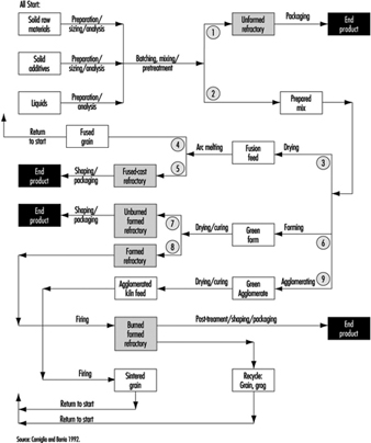
These generic flow diagrams represent thousands of specific processes, differentiated, for example, by their raw materials lists, the manner of preparation and the sizing and batching (meaning quantity weighed out) of each, the sequence and manner of mixing and so on. Omissions are allowed—for example, some unformed refractories are dry-mixed and never wetted until installation.
Refractories or products may be preformed (shaped) or formed and installed on site, but in general are supplied in the following shapes:
Brick. The standard dimensions of a refractory brick are 23 cm long by 11.4 cm wide and 6.4 cm thick (straight brick). Bricks may be extruded or dry-pressed on mechanical or hydraulic presses. Formed shapes may be burned before use or, in the case of pitch, resin or chemically bonded brick (cured).
Fusion-cast shapes. Refractory compositions are arc-melted and cast into shapes (e.g., glass-tank flux blocks as large as 0.33, 0.66, 1.33 m). After casting and annealing, the blocks are accurately ground to ensure a precise fit.
Cast and hand-moulded refractories. Large shapes, such as burner blocks and flux blocks, and intricate shapes, such as glass feeder parts, saggers and the like, are produced by either slip or hydraulic cement casting or hand-moulding techniques. Because these techniques are labour intensive, they are reserved for articles that cannot be satisfactorily formed in other ways.
Insulating refractories. Insulating refractories in the form of brick are much lighter than conventional brick of the same composition by virtue of the brick porosity.
Castables and gunning mixes. Castables consist of refractory grains to which a hydraulic binder is added. Upon mixing with water, the hydraulic agent reacts and binds the mass together. Gunning mixes are designed to be sprayed through a nozzle under water and air pressure. The mixture may be slurried before being shot through the gun, or mixed with water at the nozzle.
Plastic refractories and ramming mixes. Plastic refractories are mixtures of refractory grains and plastic clays or plasticizers with water. Ramming mixes may or may not contain clay and are generally used with forms. The amount of water used with these products varies but is held to a minimum.
Occupational Hazards and Precautions
Table 5 provides information on many of the potential hazards found in this industrial sector.
Table 5. Potential health and safety hazards found during manufacturing of glass, ceramic and related materials
|
Hazards |
Uses or sources of exposure |
Potential effects (physical hazards |
Precautions or control strategies |
|
Ergonomic stressors; biomechanical hazards |
Overexertion from manual material-handling practices and excessive force, poor posture, high frequency/duration of tasks involving lifting, pushing or pulling |
Strains, sprains and run in skeletal muscular damage to back, upper and lower extremities Excessive physical and mental fatigue can cause errors leading to secondary incidents |
|
|
Physical hazards |
Caught in or struck by or against fixed or mobile equipment Slips, trips and falls on walking and working surfaces, hoses and other equipment, tools or materials |
Abrasions, cuts, contusions, lacerations, punctures, fractures, amputations |
|
|
Noise |
Pneumatic vibrators, compressors, valve actuators, mixing drive motors, blowers and dust collectors, conveyors, powered industrial trucks, mechanized process and packaging equipment, etc. |
Occupational hearing loss, communication difficulty and stress |
|
|
Radiant heat, high-temperature work environments |
Heating or melting processes during maintenance or emergency response activities |
Physiological strain, heat stress or thermal burns |
|
|
Inhalation of airborne particulate matter from raw materials including crystalline silica, clay, lime, iron oxide, nuisance dusts |
Handling raw materials and during production Exposures during routine maintenance activities, demolition and during construction activities or rebuilds Exposures can occur from non-ventilated equipment or from leaks or poor seals at transfer points, chutes, conveyors, elevators, screens, sieves, mixing equipment, grinding or crushing machines, storage bins, valves, piping, drying or curing ovens, shaping operations, etc. Raw materials are extremely abrasive, causing deterioration of transfer or storage system components in manufacturing processes. Failure to maintain baghouses, scrubbers or dust collectors and use of compressed air for clean-up activities increases risk of overexposures Intense heating processes may lead to exposure to the most hazardous forms of silica (cristobalite or tridymite) |
Range from irritation (nuisance particulate) to chemical burns (burnt lime or other alkaline raw materials) to chronic effects such as decreased pulmonary function, lung disease, pneumoconiosis silicosis, tuberculosis |
|
|
Lacerations, abrasions, or foreign bodies; contact with sharp glass, pottery or ceramics fragments or objects |
Flying glass, ceramics or other fragments may cause penetrating wounds and serious eye injury. A special risk exists when toughened glass “explodes” during manufacture Direct contact with glass or other filaments, especially in forming or winding in continuous filament production operations and coating Drawing operations in optical fibre manufacturing |
Puncture wounds, lacerations or abrasion of skin and soft tissues (tendons, ligaments, nerves, muscle), and foreign bodies in the eye Risks of serious secondary infections or dermal exposures to corrosive or toxic materials |
|
|
Lacerations from hand-tools |
Razor knives, finger knives, cullet knives or other sharp hand tools are commonly used in production, packaging and warehousing areas or during maintenance activities |
Cuts to finger(s) or hand(s) and to lower extremities (legs) |
|
|
Heavy metals particulates or fumes (lead, cadmium, chromium, arsenic, copper, nickel, cobalt, manganese or tin) |
As raw materials or impurities in glazes, product formulas, pigments, colouring agents, films or coatings Maintenance and construction activities involving soldering, cutting, welding and applying/ removal of protective coatings Grinding, cutting, welding, drilling, or shaping fabricated metal parts, structural members or machinery (e.g., refractory blocks or high-temperature alloys) that are components of manufacturing processes |
Heavy metal toxicity |
|
|
Formaldehyde via inhalation or direct contact |
Component of binders and sizes in vitreous fibre industry Potential exposures during mixing of binders or sizes, and during production |
Sensory irritation, and irritation of respiratory tract Probable human carcinogen |
|
|
Bases (sodium hydroxide) or acids (hydrochloric acid, sulphuric acid, hydro-fluoric acid) |
Process water, boiler water or wastewater treatment and pH control Acid cleaning or etching processes with hydrofluoric acid |
Corrosive to skin or eyes Respiratory tract and mucous membrane irritant Hydrofluoric acid causes severe shin burns that can go undetected for hours |
|
|
Epoxies, acrylates and urethanes (may contain solvents such as xylene, toluene, etc.) |
Ingredients in resins, sizes, binders and coatings used in production Maintenance products |
Potential sensitizers to skin or respiratory tract Some epoxies contain unreacted epichlorohydrin, a suspect carcinogen Some urethanes contain unreacted toluene diisocyanate, a suspected carcinogen Amine curatives used in some systems—irritants or corrosives Flammability hazard |
|
|
Styrene |
Polyester resins containing styrene, size ingredients |
Irritant to eyes, skin, respiratory tract; effects on central nervous system (CNS) and target organs Possible carcinogen Flammability hazard |
|
|
Silanes |
Adhesion promoters added to sizes, binders or coatings. Can hydrolyze to release ethanol, methanol, butanol or other alcohols |
Irritant to eyes, skin and respiratory system; potential CNS effects. Splashes in eye can cause permanent damage Flammability hazard |
|
|
Latex |
Size or binder mixing areas, coatings and some maintenance products |
Irritant to skin and eyes. Some may contain formaldehyde or other biocides and/or solvents |
|
|
Catalysts and accelerators |
Added to resins or binders for curing in production and/or for some maintenance products |
Irritants or corrosives to skin or eyes. Some are highly reactive and temperature sensitive |
|
|
Hydrocarbon solvents and/or chlorinated solvents |
Maintenance shops and parts-cleaning operations |
Various—irritation, chemical dermatitis, CNS effects. Non-chlorinated solvents may be flammable Chlorinated solvent can decompose if burned or heated |
|
|
Propane, natural gas, gasoline, fuel oil |
Fuels for process heat Fuels for powered industrial trucks |
Fire and explosion hazards Exposure to carbon monoxide or other products of incomplete combustion |
|
|
Inhalation of bioaerosols |
Aerosols containing bacteria, moulds or fungus generated from spraying process or cooling water in humidification processes, cooling towers, ventilation systems, wet clean-up activities |
Waterborne illness with systemic non specific flu-like symptoms, fatigue Potential for dermatitis |
|
|
Fibrous glass, mineral wool fibre, refractory ceramic fibres |
In manufacturing processes including fibre formation, heat curing, cutting or cubing, winding, packaging and fabrication In use of fibrous materials as a component of furnaces, ducts and process equipment |
Non-respirable fibres can cause mechanical irritation to skin or eyes Respirable fibres can cause irritation to eyes, skin and respiratory tract. Durable fibres have caused fibrosis and tumours in animal studies |
|
Safety and Health Problems and Disease Patterns
This section provides an overview of industry-wide documented or suspected safety and health problems. International data on injuries and illnesses in this business sector were not located in literature searches and searches on the Internet (in 1997). Information compiled by the US Department of Labor, Occupational Safety and Health Administration (OSHA) and Bureau of Labor Statistics (BLS), was used to identify common hazards in the workplace and to describe characteristics of injuries and illnesses. These data should be representative of the situation worldwide.
Hazards detected during inspections
Regulatory compliance inspections of companies in the stone, clay, glass and concrete products manufacturing (Standard Industrial Classification (SIC) Code 32, equivalent to ISIC Code 36) reveal some of the common hazards in this sector. Regulatory compliance citations issued by OSHA indicate that common health and safety issues can be grouped as follows:
- hazard communication of physical and health hazards of chemical substances in the workplace
- control of hazardous energy—lockout and tagout procedures to control activities around machinery or equipment where un-expected energization or release of stored energy could cause injury. Hazardous energy includes electrical, mechanical, hydraulic, pneumatic, chemical, thermal radiation and other sources.
- electrical safety, including electrical equipment or system design, wiring methods, safe work practices and training
- permit required confined-space entry—identification, evaluation and safe entry procedures
- personal protective equipment—assessments, selection and use of eye, face, hand, foot and head protection
- guarding machines, equipment and tools to protect operators and adjacent workers from hazards at point of operation, ingoing nip points, and from rotating parts, flying chips or sparks; includes fixed machinery, portable machinery and portable power tools, and adjustment of guards and work rests on abrasive wheel machinery (grinders) (see figure 18)
Figure 18. Machine guarding protects operators
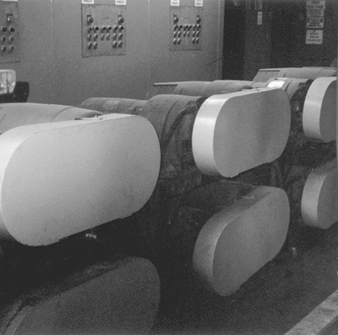
- respiratory protection—selection, use, maintenance, training, medical clearance and fit testing of respirators
- occupational noise exposure—control of exposures by engineering, administrative or hearing protection and implementation of hearing conservation programmes
- fire prevention and emergency preparedness and response, including fire extinguishers, escape routes, plans and flammable/combustible materials storage or use
- walking and working surfaces, including guarding floor and wall openings and holes; housekeeping; and keeping aisles and passageways free from conditions that present slip, trip or fall hazards (see figure 19)
Figure 19. Trip & slip hazards
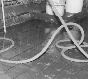
- powered industrial trucks—design, maintenance, use and other safety requirements for fork-lift trucks, platform trucks, tractors, motorized hand trucks or other specialized industrial trucks powered by electric motors or internal combustion motors
- fixed and portable ladders, stairways and scaffolds—design, inspection or maintenance and safe use
- fall protection—use of fall restraints and arrest equipment for elevated work
- cutting and welding—safe use and procedures for oxygen/acetylene or fuel gas or arc cutting or welding equipment
- material-handling equipment—including overhead and gantry cranes, hoists, chains and slings
- control of exposure to toxic or hazardous substances, including air contaminants or specifically regulated chemicals (e.g., silica, lead, asbestos, formaldehyde, cadmium or arsenic).
Injury and Illness Profile
Injury illness incidence rates
Based on records from the US Department of Labor, manufacturers of stone, clay and glass products (SIC 32) have a total “recordable” incidence rate of nonfatal occupational injuries and illnesses of 13.2 cases per 100 full-time workers per year. This incidence rate is higher than corresponding rates for all manufacturing (12.2) and all private industry (8.4). About 51% of the “recordable injury” cases in the stone, clay and glass product manufacturing sector do not result in lost work days (time away from work).
The “total lost workday case” incidence rates based on the number of disabling injuries or illnesses resulting in a worker missing days of work per 100 full-time workers are also available from the US Department of Labor. The total lost workday incidence rate includes cases where workdays are lost and the worker is not capable of performing the full scope of the job (restricted or light duty). Stone, clay and glass products manufacturers have a total lost workday incidence rate of 6.5 cases per 100 workers per year. This is higher than the corresponding rates for all manufacturing (5.5) and for all private industry (3.8). About 93% of the lost workday cases in the stone, clay and glass product manufacturing sector results from injuries rather than occupational illnesses.
Table 6 presents more detailed information on incidence rates for injuries and illnesses (combined) or injuries (alone) for various types of manufacturing processes within the stone, clay, and glass product manufacturing sector (SIC Code 32). Incidence rates and demographics may not be representative of global information, but it is the most complete information available.
Table 6. Nonfatal occupational injury and illness incidence rates1 per 100 full-time workers for US companies in SIC Code 32, private industry and manufacturing, 1994
|
Industry |
SIC Code2 |
1994 Annual Average Employment3 (thousands) |
Injuries and Illnesses |
Injuries |
||||||
|
Lost Workday Cases |
Lost Workday Cases |
|||||||||
|
Total Cases |
Total4 |
With days away from work |
Cases without Lost Workdays |
Total Cases |
Total5 |
With days away from work5 |
Cases without Lost workdays |
|||
|
Private industry, all |
95,449.3 |
8.4 |
3.8 |
2.8 |
4.6 |
7.7 |
3.5 |
2.6 |
4.2 |
|
|
Manufacturing, all |
18,303.0 |
12.2 |
5.5 |
3.2 |
6.8 |
10.4 |
4.7 |
2.9 |
5.7 |
|
|
Stone, clay and glass products |
32 |
532.5 |
13.2 |
6.5 |
4.3 |
6.7 |
12.3 |
6.1 |
4.1 |
6.2 |
|
Flat glass |
321 |
15.0 |
21.3 |
6.6 |
3.1 |
14.7 |
17.3 |
5.2 |
2.6 |
12.1 |
|
Glass and glassware, pressed |
322 |
76.8 |
12.5 |
6.0 |
3.0 |
6.5 |
11.3 |
5.5 |
2.8 |
5.8 |
|
Glass containers |
3221 |
33.1 |
14.1 |
6.9 |
3.4 |
7.2 |
13.2 |
6.5 |
3.2 |
6.7 |
|
Pressed and blown glass, nec |
3229 |
43.7 |
11.3 |
5.4 |
2.8 |
5.9 |
9.8 |
4.8 |
2.4 |
5.1 |
|
Products of purchased glass |
323 |
60.7 |
14.1 |
6.1 |
3.1 |
8.0 |
12.7 |
5.4 |
2.9 |
7.4 |
|
Structural clay products |
325 |
32.4 |
14.1 |
7.7 |
4.2 |
6.5 |
13.1 |
7.2 |
4.0 |
5.9 |
|
Brick and structural clay tile |
3251 |
- |
15.5 |
8.4 |
5.1 |
7.1 |
14.8 |
7.9 |
5.0 |
6.9 |
|
Clay refractories |
3255 |
- |
16.0 |
9.3 |
4.7 |
6.8 |
15.6 |
9.3 |
4.7 |
6.4 |
|
Pottery and related products |
326 |
40.8 |
13.6 |
6.8 |
3.8 |
6.8 |
12.2 |
6.1 |
3.5 |
6.1 |
|
Vitreous plumbing fixtures |
3261 |
- |
17.8 |
10.0 |
3.8 |
7.8 |
16.1 |
9.0 |
3.5 |
7.1 |
|
Vitreous china table and |
3262 |
- |
12.8 |
6.3 |
4.4 |
6.5 |
11.0 |
5.6 |
3.8 |
5.5 |
|
Porcelain electrical supplies |
3264 |
- |
11.3 |
5.8 |
3.7 |
5.6 |
9.8 |
5.0 |
3.4 |
4.8 |
|
Pottery products, nec |
3269 |
- |
12.6 |
5.6 |
3.7 |
7.1 |
11.6 |
5.0 |
3.5 |
6.6 |
|
Concrete, gypsum and plaster |
327 |
198.3 |
13.4 |
7.0 |
5.6 |
6.4 |
13.0 |
6.9 |
5.5 |
6.2 |
|
Concrete block and brick |
3271 |
17.1 |
14.5 |
7.8 |
6.8 |
6.8 |
14.0 |
7.7 |
6.7 |
6.2 |
|
Concrete products, nec |
3272 |
65.6 |
17.7 |
9.8 |
7.0 |
7.9 |
17.1 |
9.5 |
6.8 |
7.6 |
|
Ready-mixed concrete |
3273 |
98.8 |
11.6 |
6.0 |
5.3 |
5.6 |
11.5 |
6.0 |
5.3 |
5.5 |
|
Misc. nonmetallic mineral |
329 |
76.7 |
10.7 |
5.4 |
3.3 |
5.3 |
9.8 |
5.0 |
3.2 |
4.9 |
|
Abrasive products |
3291 |
20.0 |
10.2 |
3.9 |
2.5 |
6.3 |
9.5 |
3.7 |
2.4 |
5.8 |
|
Mineral wool |
3296 |
23.4 |
11.0 |
6.1 |
3.0 |
4.9 |
10.0 |
5.6 |
2.7 |
4.3 |
|
Nonclay refractories |
3297 |
- |
10.6 |
5.8 |
4.5 |
4.8 |
10.2 |
5.7 |
4.3 |
4.6 |
|
Nonmetallic mineral products, |
3299 |
- |
13.1 |
8.2 |
5.8 |
4.9 |
11.4 |
7.0 |
5.5 |
4.3 |
nec = not elsewhere classified
- = data not available
1 The incidence rates represent the number of injuries and illnesses per 100 full-time workers and were calculated as number of injuries and illnesses divided by hours worked by all employees in the calendar year times 200,000 (the base equivalent for 100 workers at 40 hours per week for 52 weeks per year).
2 Standard Industrial Classification Manual 1987 Edition.
3 Employment is expressed as an annual average and was derived primarily from the BLS State Current Employment Statistics programme.
4 Total cases includes cases involving restricted work activity only, in addition to days away from work cases with or without restricted work activity.
5 Days away from work cases include those which result from days away from work, with or without restricted work activity.
Source = Source: Based on national survey of work-related injuries and illnesses in private industry by the US Department of Labor, Bureau of Labor Statistics.
Demographics of injuries and illness cases
Workers aged 25 to 44 years accounted for about 59% of the 23,203 lost-time injury or illness cases in the U.S. stone, clay and glass product manufacturing sector. The next highest affected group was workers aged 45 to 54 years, who had 18% of the lost-time injury or illness cases (see figure 20).
Figure 20. Lost-time injuries & illnesses by age; US
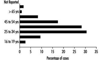
About 85% of the lost-time injury cases injuries and illnesses in SIC Code 32 were males. In 24% of the lost-time cases (both sexes), workers had less than 1 year of service in the job. Workers with 1 to 5 years of service in the job accounted for 32% of the cases. Experienced employees with more than 5 years of service comprised 35% of the lost-time cases.
Nature. Analysis of lost-time incident profiles characterizes the nature of the disabling injuries and illnesses and helps explain causative or contributing factors. Strains and sprains are the leading nature of injury and illness in the stone, clay and glass product manufacturing sector. As shown in figure 23, strains and sprains make up about 42% of all lost-time cases. Cuts and punctures (10%) were the second most common nature of disabling injury or illness. Other major nature of injury categories were bruises (9%), fractures (7%) and back/other pain (5%). Heat burns, chemical burns and amputations were less common (1% or less).
Figure 21. Occupational injuries & illnesses
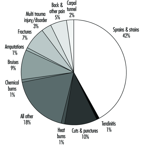
Events or exposures. Figure 22 shows that overexertion while lifting leads all other disabling injury events or exposures. Over exertion while lifting was a causative factor in about 17% of the disabling cases; repetitive motion was the exposure in an additional 5% of the disabling cases. Struck by an object was the next most common event, which led to 16% of the cases. Struck against an object events caused 10% of the cases. Other important events were caught in an object (9%), falls on same level (9%), falls to lower level (6%), and slips/trips without a fall (6%). Exposure to harmful substances or environment was a causative factor in only 5% of the cases.
Figure 22. Event or exposure in occupational injuries
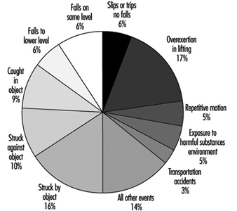
Body part. The body part most frequently affected was the back (24% of the cases) (see figure 23). Injuries to the upper extremities (finger, hand, wrist and arm combined) occurred in 23% of the cases, with injury to the finger in 7% of the cases. Lower-extremity injuries was similar (22% of cases), with the knee affected in 9% of the cases.
Figure 23. Body part affected in lost workday injury
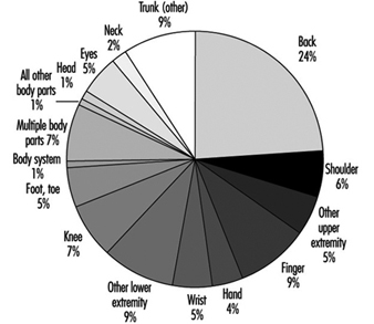
Sources. The most common sources of disabling injury or illness cases were: parts and materials (20%); worker position or motion (16%); floors, walkways or ground surfaces (15%); containers (10%); machinery (9%); vehicles (9%); handtools (4%); furniture and fixtures (2%); and chemicals and chemical products (2%) (see figure 24).
Figure 24. Sources of occupational injuries
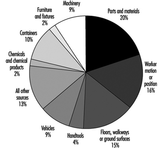
Disease prevention and control
Cumulative trauma associated with repetitive motion, overexertion and excessive forces is a common finding in this manufacturing sector. Robotic devices are available in some instances, but manual handling practices still dominate. Compressors, blowers, spinners, pneumatic vibrators and packaging equipment can create noise exceeding 90 to 95 dBA. Hearing protection and a sound hearing conservation programme will prevent permanent changes in hearing.
This industry consumes large quantities of crystalline silica. Exposures must be limited during handling, maintenance and cleaning. Good housekeeping with a proper vacuum system or wet cleaning methods will reduce potential exposures. Periodic screening should be conducted utilizing pulmonary function tests and chest films if excessive exposure to silica has occurred. Exposures to heavy metals found as raw materials, glazing or pigments should also be minimized. Using substitutes for heavy metals found in glazes will also eliminate health concerns regarding leaching of metals into food or beverages. Good housekeeping practices and respiratory protection are used to prevent adverse effects. Medical surveillance that includes biological monitoring may be necessary.
The use of binders containing formaldehyde, epoxies and silanes is common in the manufacture of vitreous fibres. Steps must be taken to minimize skin and respiratory irritation. Formaldehyde is regulated as a carcinogen in many countries. Respirable fibres are produced during manufacturing, fabrication, cutting and installation of glass, rock, slag, and refractory ceramic fibre products. Although exposures to airborne fibres have generally been quite low (less than 1 fibre per cubic centimetre) for most of these materials, loose fill blowing applications tend to be much higher.
Rock, slag, and glass are among the most extensively studied commercial insulation products in use today. Epidemiological studies have revealed that cigarette smoking is having a major impact on lung cancer mortality among manufacturing employees. Well-conducted cross-sectional studies have not shown that the fibres produce excess lung mortality or morbidity. Recent chronic inhalation studies in rats have shown that the durability of vitreous fibres is a critical determinant of the biological potential of these fibres. Composition, which determines the durability of these fibres, may vary considerably. To avoid public health concerns, a European Commission Technical Committee has recently proposed that the bio-persistence of vitreous fibres be tested using short-term inhalation. An insulation wool composition which has been thoroughly tested at maximum tolerated dose by chronic inhalation in rats and found not to produce irreversible disease is suggested as a reference fibre.
Environmental and Public Health Issues
The primary air pollutant emitted during the manufacture of glass, ceramics, pottery and brick is particulate matter. Maximum achievable control technology consisting of baghouses and wet electrostatic precipitators is available to reduce emissions when necessary. Hazardous air pollutants generated during binder mixing, application and curing processes are coming under scrutiny. These substances include styrene, silanes and epoxies used on continuous glass filament, and formaldehyde, methanol and phenol utilized during rock, slag and glass production. Formaldehyde is the hazardous air pollutant that is driving the control standards for the latter manufacturing lines. Heavy metal hazardous air pollutants such as chromium are driving glass melting furnace standards while NOx and SOx remain issues in some countries. Fluoride and boron emissions are of concern in continuous glass filament production. Boron may also become an environmental concern if highly soluble vitreous glass wool fibres are required in some countries.
Due to the high discharge volume of air and the nature of forming and glass melting, the industry evaporates considerable quantities of water. Many facilities, as, for example, in the United States, have zero discharge of wastewater. Recycled wastewater that contains organic material can create biological hazards in the workplace if treatment is not implemented to prevent biological growth (see figure 25). Waste generated by this industrial sector includes heavy metals, corrosives, some binders and spent solvents. The glass fibre industry has become a major point for recycling glass bottles and plate glass. For example, current glass wool products contain 30 to 60% recycled glass. Spent refractories are also reclaimed and beneficially reused.
Figure 25. Aerosols of reused waste water
Acknowledgements: Special thanks to Dan Dimas, CSP, Libbey-Owens-Ford, for providing photographs, and to Michel Soubeyrand, Libbey-Owens-Ford, for providing information on chemical vapour deposition for the section on glass.
Environmental and Public Health Issues
Industry Overview
The electronics industry, compared to other industries, has been viewed as “clean” in terms of its environmental impact. None the less, the chemicals used in the manufacture of electronic parts and components, and the waste generated, create significant environment issues that must be addressed on a global scale due to the size of the electronics industry. The wastes and by-products derived from the manufacture of printed wiring boards (PWBs), printed circuit boards (PCBs) and semiconductors are areas of interest that the electronic industry has vigorously pursued in terms of pollution prevention, treatment technology and recycling/reclamation techniques.
To a large degree, the incentive to control the environmental footprint of electronic processes has migrated from an environmental impetus to a financial domain. Due to the costs and liabilities associated with hazardous waste and emissions, the electronics industry has aggressively implemented and developed environmental controls that have greatly reduced the impact of its by-products and waste. In addition, the electronics industry has taken a proactive approach to incorporate environmental goals, tools and techniques into its environmentally conscious businesses. Examples of this proactive approach are the phase-out of CFCs and perfluorinated compounds and the development of “environmentally friendly” alternatives, as well as the emerging “design for the environment” approach to product development.
The manufacture of PWBs, PCBs and semiconductors requires the use of a variety of chemicals, specialized manufacturing techniques and equipment. Due to the hazards associated with these manufacturing processes, the proper management of chemical by-products, wastes and emissions is essential to assure the safety of the industry’s employees and the protection of the environment in the communities in which they reside.
Table 1, table 2 and table 3 present an outline of the key by-products and wastes that are generated in the manufacturing of PWBs, PCBs and semiconductors. In addition, the tables present the main types of environmental impact and the generally accepted means of mitigation and control of the waste stream. Primarily, the wastes that are generated affect industrial wastewater or the air, or become a solid waste.
Table 1. PWB waste generation and controls
|
Process steps |
Hazardous |
Environmental |
Controls1 |
|
Material |
None |
None |
None |
|
Stack and pin |
Heavy/precious metals |
Solid waste2 |
Recycle/reclaim |
|
Drilling |
Heavy/precious metals |
Solid waste2 |
Recycle/reclaim |
|
Deburr |
Heavy/precious metals |
Solid waste2 |
Recycle/reclaim |
|
Electroless |
Metals |
Wastewater |
Chemical precipitation |
|
Imaging |
Solvents |
Air |
Adsorption, condensation or |
|
Pattern plating |
Corrosives |
Wastewater/air |
pH neutralization/air scrubbing |
|
Strip, etch, strip |
Ammonia |
Air |
Air scrubbing (adsorption) |
|
Solder mask |
Corrosives |
Air |
Air scrubbing (adsorption) |
|
Solder coating |
Solvents |
Air |
Adsorption, condensation or |
|
Gold plating |
Corrosives |
Air |
Air scrubbing (adsorption) |
|
Component |
Solvents |
Air |
Adsorption condensation or |
1. Use of mitigation controls depends upon discharge limits in the specific location.
2. A solid waste is any discarded material regardless of its state.
Table 2. PCB waste generation and controls
|
Process steps |
Hazardous |
Environmental |
Controls |
|
Cleaning |
Metals (lead) |
Wastewater |
pH neutralization, chemical |
|
Solder paste |
Solder paste (lead/tin) |
Solid waste |
Recycle/reclaim |
|
Adhesive |
Epoxy glues |
Solid waste |
Incineration |
|
Component |
Plastic tapes, reels and tubes |
||
|
Adhesive cure and |
|||
|
Fluxing |
Solvent (IPA flux) |
Solid waste |
Recycle |
|
Wave soldering |
Metal (solder dross) |
Solid waste |
Recycle/reclaim |
|
Inspection and |
Metal |
Solid waste |
Recycle/reclaim |
|
Testing |
Scrapped populated |
Solid waste |
Recycle/reclaim |
|
Reworking and |
Metal (solder dross) |
Solid waste |
Recycle/reclaim |
|
Support |
Metal |
Solid waste |
Recycle/incineration |
Table 3. Semiconductor manufacturing waste generation and controls
|
Process steps |
Hazardous |
Environmental |
Controls |
|
Lithography/etching |
Solvents |
Solid waste |
Recycle/reclaim/incineration |
|
Oxidation |
Solvents |
Solid waste |
Recycle/reclaim/incineration |
|
Doping |
Poison gas (arsine, |
Air |
Substitution with liquid |
|
Chemical vapour deposition |
Metals Corrosives |
Solid waste |
Incineration |
|
Metallization |
Solvents |
Solid waste |
Incineration |
|
Assembly and testing |
Solvents |
Solid waste |
Recycle/reclaim/incineration |
|
Cleaning |
Corrosives |
Wastewater |
pH neutralization |
The following are generally accepted means of mitigating emissions in the PWB, PCB and semiconductor industries. The controls of choice will vary according to engineering capabilities, regulatory agency requirements and the specific constituents/concentrations of the waste stream.
Wastewater Control
Chemical precipitation
Chemical precipitation is generally used in the removal of particulate or soluble metals from wastewater effluents. Since metals do not naturally degrade and are toxic at low concentrations, their removal from industrial wastewater is essential. Metals can be removed from wastewater by chemical means since they are not very soluble in water; their solubilities depend upon the pH, metal concentration, type of metal and the presence of other ions. Typically, the waste stream requires pH adjustment to the proper level to precipitate out the metal. The addition of chemicals to wastewater in an effort to alter the physical state of dissolved and suspended solids is required. Lime, caustic and sulphide precipitation agents are commonly used. The precipitating agents facilitate the removal of dissolved and suspended metals by coagulation, sedimentation or entrapment within a precipitate.
A result of chemical precipitation of wastewater is the accumulation of sludge. Therefore, dewatering processes have been developed to reduce the weight of the sludge by means of centrifuges, filter presses, filters or drying beds. The resultant dewatered sludge can then be sent off for incineration or landfill.
pH neutralization
pH (the hydrogen-ion concentration or acidity) is an important quality parameter in industrial wastewater. Due to the adverse effects of pH extremes in natural waters and on sewage treatment operations, the pH of industrial wastewater must be adjusted prior to discharge from the manufacturing facility. Treatment occurs in a series of tanks that are monitored for the hydrogen-ion concentration of the wastewater effluent. Typically, hydrochloric or sulphuric acid is used as neutralizing corrosives, and sodium hydroxide is used as a neutralizing caustic. The neutralizing agent is metered into the wastewater effluent to adjust the pH of the discharge to its desired level.
Adjustment of pH is often required prior to the application of other wastewater treatment processes. Such processes include chemical precipitation, oxidation/reduction, activated carbon sorption, stripping and ion exchange.
Solid Waste Control
Materials are a solid waste if they are abandoned or discarded by being disposed of; burned or incinerated; or accumulated, stored or treated before or in lieu of being abandoned (US Code of Federal Regulation 40, Section 261.2). Hazardous waste generally exhibits one or more of the following characteristics: ignitability, corrosivity, reactivity, toxicity. Depending upon the characteristic of the hazardous material/waste, various means are used to control the substance. Incineration is a common treatment alternative for solvent and metal wastes generated during PWB, PCB and semiconductor manufacturing.
Incineration
Incineration (afterburner) or thermal destruction has become a popular option in handling ignitable and toxic wastes. In many instances, ignitable wastes (solvents) are used as a fuel source (fuel blending) for thermal and catalytic incinerators. Proper incineration of solvents and toxic wastes provides complete oxidation of the fuel and converts combustible material to carbon dioxide, water and ash, thereby leaving no liabilities associated with residual hazardous waste. The common types of incineration are thermal and catalytic incinerators. The selection of the type of incineration method is dependent upon the combustion temperature, fuel characteristics and residence time. Thermal incinerators operate at high temperatures and are widely used with halogenated compounds. Types of thermal incinerators include rotary kiln, liquid injection, fixed-hearth, fluidized bed and other advanced design incinerators.
Catalytic incinerators oxidize combustible materials (e.g., VOCs) by injecting a heated gas stream through a catalyst bed. The catalyst bed maximizes surface area, and by injecting a heated gas stream into the catalyst bed combustion can occur at a lower temperature than thermal incineration.
Air Emissions
Incineration is also used in control of air emissions. Absorption and adsorption are used as well.
Absorption
Air absorption is typically used in the scrubbing of corrosive air emissions, by passing the contaminant through and dissolving it in a non-volatile liquid (e.g., water). The effluent from the absorption process is typically discharged to a wastewater treatment system, where it undergoes pH adjustment.
Adsorption
Adsorption is the adherence (by means of physical or chemical forces) of a gas molecule to the surface of another substance, called an adsorbent. Typically, adsorption is used to extract solvents from an air emission source. Activated carbon, activated alumina or silica gel are commonly used adsorbents.
Recycling
Recyclable materials are used, reused or reclaimed as ingredients in an industrial process to make a product. Recycling of materials and waste provides environmental and economic means of effectively addressing specific types of waste streams, such as metals and solvents. Materials and wastes can be recycled in-house, or secondary markets may accept recyclable materials. The selection of recycling as an alternative for wastes must be evaluated against financial considerations, the regulatory framework and available technology to recycle the materials.
Future Direction
As the demand for pollution prevention increases and industry seeks cost-effective means to address chemical use and waste, the electronics industry must evaluate new techniques and technologies to improve the methods for hazardous-materials handling and waste generation. The end-of-pipe approach has been replaced by design for the environment techniques, where environmental issues are addressed over the full life cycle of a product, including: material conservation; efficient manufacturing operations; the use of more environmentally friendly materials; recycling, regeneration and reclamation of waste products; and a host of other techniques that will assure a smaller environmental impact for the electronics manufacturing industry. One example is the large amount of water that is used in the many rinsing and other processing steps in the microelectronics industry. In water-poor areas, this is forcing the industry to find alternatives. However, it is essential to make sure that the alternative (e.g., solvents) does not create additional environmental problems.
As an example of future directions in the PWB and PCB process, table 4 presents various alternatives for creating more environmentally sound practices and preventing pollution. Priority needs and approaches have been identified.
Table 4. Matrix of priority needs
|
Priority need (decreasing |
Approach |
Selected tasks |
|
More efficient use, |
Extend life of electrolytic and |
Research to extend baths. |
|
Reduce solid waste generated |
Develop and promote |
Develop infrastructure to |
|
Establish better supplier |
Promote supplier, |
Develop a model hazardous |
|
Minimize the impact of |
Reduce lead solder use when |
Change specifications to accept |
|
Use additive processes that |
Develop simplified, |
Collaborate on projects to |
|
Eliminate hole smear in PWB |
Develop no-smear resins or |
Investigate alternative |
|
Reduce water consumption |
Develop water use |
Modify specifications to reduce |
Source: MCC 1994.
" DISCLAIMER: The ILO does not take responsibility for content presented on this web portal that is presented in any language other than English, which is the language used for the initial production and peer-review of original content. Certain statistics have not been updated since the production of the 4th edition of the Encyclopaedia (1998)."