With regard to heating, a given person’s needs will depend on many factors. They can be classified into two main groups, those related to the surroundings and those related to human factors. Among those related to the surroundings one might count geography (latitude and altitude), climate, the type of exposure of the space the person is in, or the barriers that protect the space against the external environment, etc. Among the human factors are the worker’s energy consumption, the pace of work or the amount of exertion needed for the job, the clothing or garments used against the cold and personal preferences or tastes.
The need for heating is seasonal in many regions, but this does not mean that heating is dispensable during the cold season. Cold environmental conditions affect health, mental and physical efficiency, precision and occasionally may increase the risk of accidents. The goal of a heating system is to maintain pleasant thermal conditions that will prevent or minimize adverse health effects.
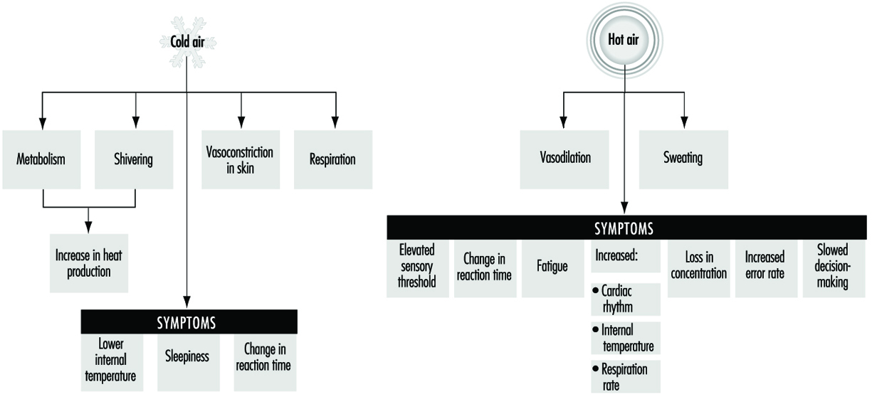
The physiological characteristics of the human body allow it to withstand great variations in thermal conditions. Human beings maintain their thermal balance through the hypothalamus, by means of thermal receptors in the skin; body temperature is kept between 36 and 38°C as shown in figure 1.
Figure 1. Thermoregulatory mechanisms in human beings
Heating systems need to have very precise control mechanisms, especially in cases where workers carry out their tasks in a sitting or a fixed position that does not stimulate blood circulation to their extremities. Where the work performed allows a certain mobility, the control of the system may be somewhat less precise. Finally, where the work performed takes place in abnormally adverse conditions, as in refrigerated chambers or in very cold climatic conditions, support measures may be undertaken to protect special tissues, to regulate the time spent under those conditions or to supply heat by electrical systems incorporated into the worker’s garments.
Definition and Description of the Thermal Environment
A requirement that can be demanded of any properly functioning heating or air conditioning system is that it should allow for control of the variables that define the thermal environment, within specified limits, for each season of the year. These variables are
- air temperature
- average temperature of the inside surfaces that define the space
- air humidity
- speeds and uniformity of speeds of air flow within the space
It has been shown that there is a very simple relation between the temperature of the air and of the wall surfaces of a given space, and the temperatures that provide the same perceived thermal sensation in a different room. This relation can be expressed as
![]()
where
Teat = equivalent air temperature for a given thermal sensation
Tdbt = air temperature measured with a dry bulb thermometer
Tast = measured average surface temperature of the walls.
For example, if in a given space the air and the walls are at 20° C, the equivalent temperature will be 20°C, and the perceived sensation of heat will be the same as in a room where the average temperature of the walls is 15°C and the air temperature is 25°C, because that room would have the same equivalent temperature. From the standpoint of temperature, the perceived sensation of thermal comfort would be the same.
Properties of humid air
In implementing an air-conditioning plan, three things that must be taken into consideration are the thermodynamic state of the air in the given space, of the air outside, and of the air that will be supplied to the room. The selection of a system capable of transforming the thermodynamic properties of the air supplied to the room will then be based on the existing thermal loads of each component. We therefore need to know the thermodynamic properties of humid air. They are as follows:
Tdbt = the dry bulb temperature reading, measured with a thermometer insulated from radiated heat
Tdpt = the dew point temperature reading. This is the temperature at which nonsaturated dry air reaches the saturation point
W = a humidity relation that ranges from zero for dry air to Ws for saturated air. It is expressed as kg of water vapour by kg of dry air
RH = relative humidity
t* = thermodynamic temperature with moist bulb
v = specific volume of air and water vapour (expressed in units of m3/kg). It is the inverse of density
H = enthalpy, kcal/kg of dry air and associated water vapour.
Of the above variables, only three are directly measurable. They are the dry bulb temperature reading, the dew point temperature reading and relative humidity. There is a fourth variable that is experimentally measurable, defined as the wet bulb temperature. The wet bulb temperature is measured with a thermometer whose bulb has been moistened and which is moved, typically with the aid of a sling, through nonsaturated moist air at a moderate speed. This variable differs by an insignificant amount from the thermodynamic temperature with a dry bulb (3 per cent), so they can both be used for calculations without erring too much.
Psychrometric diagram
The properties defined in the previous section are functionally related and can be portrayed in graphic form. This graphic representation is called a psychrometric diagram. It is a simplified graph derived from tables of the American Society of Heating, Refrigerating and Air Conditioning Engineers (ASHRAE). Enthalpy and the degree of humidity are shown on the coordinates of the diagram; the lines drawn show dry and humid temperatures, relative humidity and specific volume. With the psychrometric diagram, knowing any two of the aforementioned variables enables you to derive all the properties of humid air.
Conditions for thermal comfort
Thermal comfort is defined as a state of mind that expresses satisfaction with the thermal environment. It is influenced by physical and physiological factors.
It is difficult to prescribe general conditions that should be met for thermal comfort because conditions differ in various work situations; different conditions could even be required for the same work post when it is occupied by different people. A technical norm for thermal conditions required for comfort cannot be applied to all countries because of the different climatic conditions and their different customs governing dress.
Studies have been carried out with workers that do light manual labour, establishing a series of criteria for temperature, speed and humidity that are shown in table 1 (Bedford and Chrenko 1974).
Table 1. Proposed norms for environmental factors
|
Environmental factor |
Proposed norm |
|
Air temperature |
21 °C |
|
Average radiant temperature |
≥ 21 °C |
|
Relative humidity |
30–70% |
|
Speed of air flow |
0.05–0.1 metre/second |
|
Temperature gradient (from head to foot) |
≤ 2.5 °C |
The above factors are interrelated, requiring a lower air temperature in cases where there is high thermal radiation and requiring a higher air temperature when the speed of the air flow is also higher.
Generally, the corrections that should be carried out are the following:
The air temperature should be increased:
- if the speed of the air flow is high
- for sedentary work situations
- if clothing used is light
- when people must be acclimatized to high indoor temperatures.
The air temperature should be decreased:
- if the work involves heavy manual labour
- when warm clothing is used.
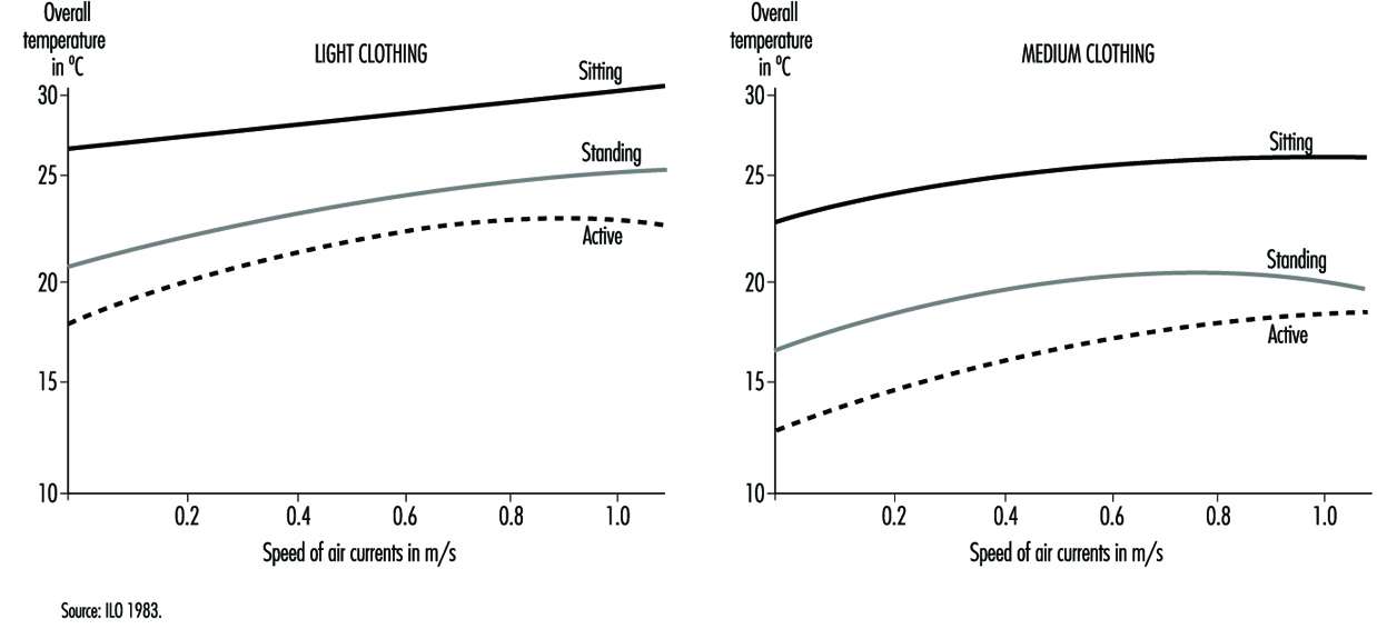
For a good sensation of thermal comfort the most desirable situation is one where the temperature of the environment is slightly higher than the temperature of the air, and where the flow of radiating thermal energy is the same in all directions and is not excessive overhead. The increase in temperature by height should be minimized, keeping feet warm without creating too much of a thermal load overhead. An important factor that has a bearing on the sensation of thermal comfort is the speed of the air flow. There are diagrams that give recommended air speeds as a function of the activity that is being carried out and the kind of clothing used (figure 2).
Figure 2. Comfort zones based on readings of overall temperatures and speed of air currents
In some countries there are norms for minimal environmental temperatures, but optimal values have not yet been established. Typically, the maximum value for air temperature is given as 20°C. With recent technical improvements, the complexity of measuring thermal comfort has increased. Many indexes have appeared, including the index of effective temperature (ET) and the index of effective temperature, corrected (CET); the index of caloric overload; the Heat Stress Index (HSI); the wet bulb globe temperature (WBGT); and the Fanger index of median values (IMV), among others. The WBGT index allows us to determine the intervals of rest required as a function of the intensity of the work performed so as to preclude thermal stress under working conditions. This is discussed more fully in the chapter Heat and Cold.
Thermal comfort zone in a psychrometric diagram
The range on the psychrometric diagram corresponding to conditions under which an adult perceives thermal comfort has been carefully studied and has been defined in the ASHRAE norm based on the effective temperature, defined as the temperature measured with a dry bulb thermometer in a uniform room with 50 per cent relative humidity, where people would have the same interchange of heat by radiant energy, convection and evaporation as they would with the level of humidity in the given local environment. The scale of effective temperature is defined by ASHRAE for a level of clothing of 0.6 clo—clo is a unit of insulation; 1 clo corresponds to the insulation provided by a normal set of clothes—that assumes a level of thermal insulation of 0.155 K m2W–1, where K is the exchange of heat by conduction measured in Watts per square metre (W m–2) for a movement of air of 0.2 m s–1 (at rest), for an exposure of one hour at a chosen sedentary activity of 1 met (unit of metabolic rate=50 Kcal/m2h). This comfort zone is seen in figure 2 and can be used for thermal environments where the measured temperature from radiant heat is approximately the same as the temperature measured by a dry bulb thermometer, and where the speed of air flow is below 0.2 m s–1 for people dressed in light clothing and carrying out sedentary activities.
Comfort formula: The Fanger method
The method developed by PO Fanger is based on a formula that relates variables of ambient temperature, average radiant temperature, relative speed of air flow, pressure of water vapour in ambient air, level of activity and thermal resistance of the clothing worn. An example derived from the comfort formula is shown in table 2, which can be used in practical applications for obtaining a comfortable temperature as a function of the clothing worn, the metabolic rate of the activity carried out and the speed of the air flow.
Table 2. Temperatures of thermal comfort (°C), at 50% relative humidity (based on the formula by PO Fanger)
|
Metabolism (Watts) |
105 |
|||
|
Radiating temperature |
clo |
20 °C |
25 °C |
30 °C |
|
Clothing (clo) |
|
|
|
|
|
0.5 |
30.5 |
29.0 |
27.0 |
|
|
1.5 |
30.6 |
29.5 |
28.3 |
|
|
Clothing (clo) |
|
|
|
|
|
0.5 |
26.7 |
24.3 |
22.7 |
|
|
1.5 |
27.0 |
25.7 |
24.5 |
|
|
Metabolism (Watts) |
157 |
|||
|
Radiating temperature |
clo |
20 °C |
25 °C |
30 °C |
|
Clothing (clo) |
|
|
|
|
|
0.5 |
23.0 |
20.7 |
18.3 |
|
|
1.5 |
23.5 |
23.3 |
22.0 |
|
|
Clothing (clo) |
|
|
|
|
|
0.5 |
16.0 |
14.0 |
11.5 |
|
|
1.5 |
18.3 |
17.0 |
15.7 |
|
|
Metabolism (Watts) |
210 |
|||
|
Radiating temperature |
clo |
20 °C |
25 °C |
30 °C |
|
Clothing (clo) |
|
|
|
|
|
0.5 |
15.0 |
13.0 |
7.4 |
|
|
1.5 |
18.3 |
17.0 |
16.0 |
|
|
Clothing (clo) |
|
|
|
|
|
0.5 |
–1.5 |
–3.0 |
/ |
|
|
1.5 |
–5.0 |
2.0 |
1.0 |
|
Heating Systems
The design of any heating system should be directly related to the work to be performed and the characteristics of the building where it will be installed. It is hard to find, in the case of industrial buildings, projects where the heating needs of the workers are considered, often because the processes and workstations have yet to be defined. Normally systems are designed with a very free range, considering only the thermal loads that will exist in the building and the amount of heat that needs to be supplied to maintain a given temperature within the building, without regard to heat distribution, the situation of workstations and other similarly less general factors. This leads to deficiencies in the design of certain buildings that translate into shortcomings like cold spots, draughts, an insufficient number of heating elements and other problems.
To end up with a good heating system in planning a building, the following are some of the considerations that should be addressed:
- Consider the proper placement of insulation to save energy and to minimize temperature gradients within the building.
- Reduce as much as possible the infiltration of cold air into the building to minimize temperature variations in the work areas.
- Control air pollution through localized extraction of air and ventilation by displacement or diffusion.
- Control the emissions of heat due to the processes used in the building and their distribution in occupied areas of the building.
When heating is provided by burners without exhaust chimneys, special consideration should be given to the inhalation of the products of combustion. Normally, when the combustible materials are heating oil, gas or coke, they produce sulphur dioxide, nitrogen oxides, carbon monoxide and other combustion products. There exist human exposure limits for these compounds and they should be controlled, especially in closed spaces where the concentration of these gases can increase rapidly and the efficiency of the combustion reaction can decrease.
Planning a heating system always entails balancing various considerations, such as a low initial cost, flexibility of the service, energy efficiency and applicability. Therefore, the use of electricity during off-peak hours when it might be cheaper, for example, could make electric heaters cost-effective. The use of chemical systems for heat storage that can then be put to use during peak demand (using sodium sulphide, for example) is another option. It is also possible to study the placement of several different systems together, making them work in such a way that costs can be optimized.
The installation of heaters that are capable of using gas or heating oil is especially interesting. The direct use of electricity means consuming first-class energy that may turn out to be costly in many cases, but that may afford the needed flexibility under certain circumstances. Heat pumps and other cogeneration systems that take advantage of residual heat can afford solutions that may be very advantageous from the financial point of view. The problem with these systems is their high initial cost.
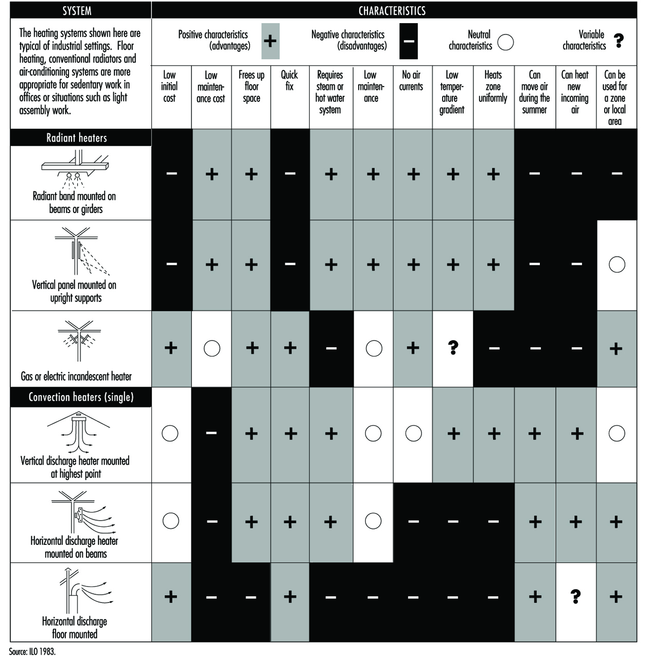
Today the tendency of heating and air conditioning systems is to aim to deliver optimal functioning and energy savings. New systems therefore include sensors and controls distributed throughout the spaces to be heated, obtaining a supply of heat only during the times necessary to obtain thermal comfort. These systems can save up to 30% of the energy costs of heating. Figure 3 shows some of the heating systems available, indicating their positive characteristics and their drawbacks.
Figure 3. Characteristics of the most common heating systems employed in worksites
Air-conditioning systems
Experience shows that industrial environments that are close to the comfort zone during summer months increase productivity, tend to register fewer accidents, have lower absenteeism and, in general, contribute to improved human relations. In the case of retail establishments, hospitals and buildings with large surfaces, air conditioning usually needs to be directed to be able to provide thermal comfort when outside conditions require it.
In certain industrial environments where external conditions are very severe, the goal of heating systems is geared more to providing enough heat to prevent possible adverse health effects than to providing enough heat for a comfortable thermal environment. Factors that should be carefully monitored are the maintenance and proper use of the air-conditioning equipment, especially when equipped with humidifiers, because they can become sources of microbial contamination with the risks that these contaminants may pose to human health.
Today ventilation and climate-control systems tend to cover, jointly and often using the same installation, the needs for heating, refrigerating and conditioning the air of a building. Multiple classifications may be used for refrigerating systems.
Depending on the configuration of the system they may be classified in the following way:
- Hermetically sealed units, with refrigerating fluid installed at the factory, that can be opened and recharged in a repair shop. These are air-conditioning units normally used in offices, dwellings and the like.
- Semi-hermetic units of medium size, factory made, that are of larger size than home units and that can be repaired through openings designed for that purpose.
- Segmented systems for warehouses and large surfaces, which consist of parts and components that are clearly differentiated and physically separate (the compressor and the condenser are physically separate from the evaporator and the expansion valve). They are used for large office buildings, hotels, hospitals, large factories and industrial buildings.
Depending on the coverage they provide, they can be classified in the following way:
- Systems for a single zone: one air treatment unit serves various rooms in the same building and at the same time. The rooms served have similar heating, refrigeration and ventilation needs and they are regulated by a common control (a thermostat or similar device). Systems of this type can end up being unable to supply an adequate level of comfort to each room if the design plan did not take into consideration the different thermal loads between rooms in the same zone. This may happen when there is an increase in the occupancy of a room or when lighting or other heat sources are added, like computers or copying machines, that were unforeseen during the original design of the system. Discomfort may also occur because of seasonal changes in the amount of solar radiation a room receives, or even because of the changes from one room to the next during the day.
- Systems for multiple zones: systems of this type can provide different zones with air at different temperatures and humidities by heating, cooling, humidifying or dehumidifying air in each zone and by varying the flow of air. These systems, even if they generally have a common and centralized air cooling unit (compressor, evaporator, etc.), are equipped with a variety of elements, such as devices that control the flow of air, heating coils and humidifiers. These systems are capable of adjusting the conditions of a room based on specific thermal loads, which they detect by means of sensors distributed in the rooms throughout the area they serve.
- Depending on the flow of air that these systems pump into the building they are classified in the following way:
- Constant volume (CV): these systems pump a constant flow of air into each room. Temperature changes are effected by heating or cooling the air. These systems frequently mix a percentage of outside air with recycled indoor air.
- Variable volume (VAV): these systems maintain thermal comfort by varying the amount of heated or cooled air supplied to each space. Even though they function primarily based on this mixing principle, they can also be combined with systems that change the temperature of the air they introduce into the room.
The problems that most frequently plague these types of systems are excess heating or cooling if the system is not adjusted to respond to variations in thermal loads, or a lack of ventilation if the system does not introduce a minimal amount of outside air to renew the circulating indoor air. This creates stale indoor environments in which the quality of air deteriorates.
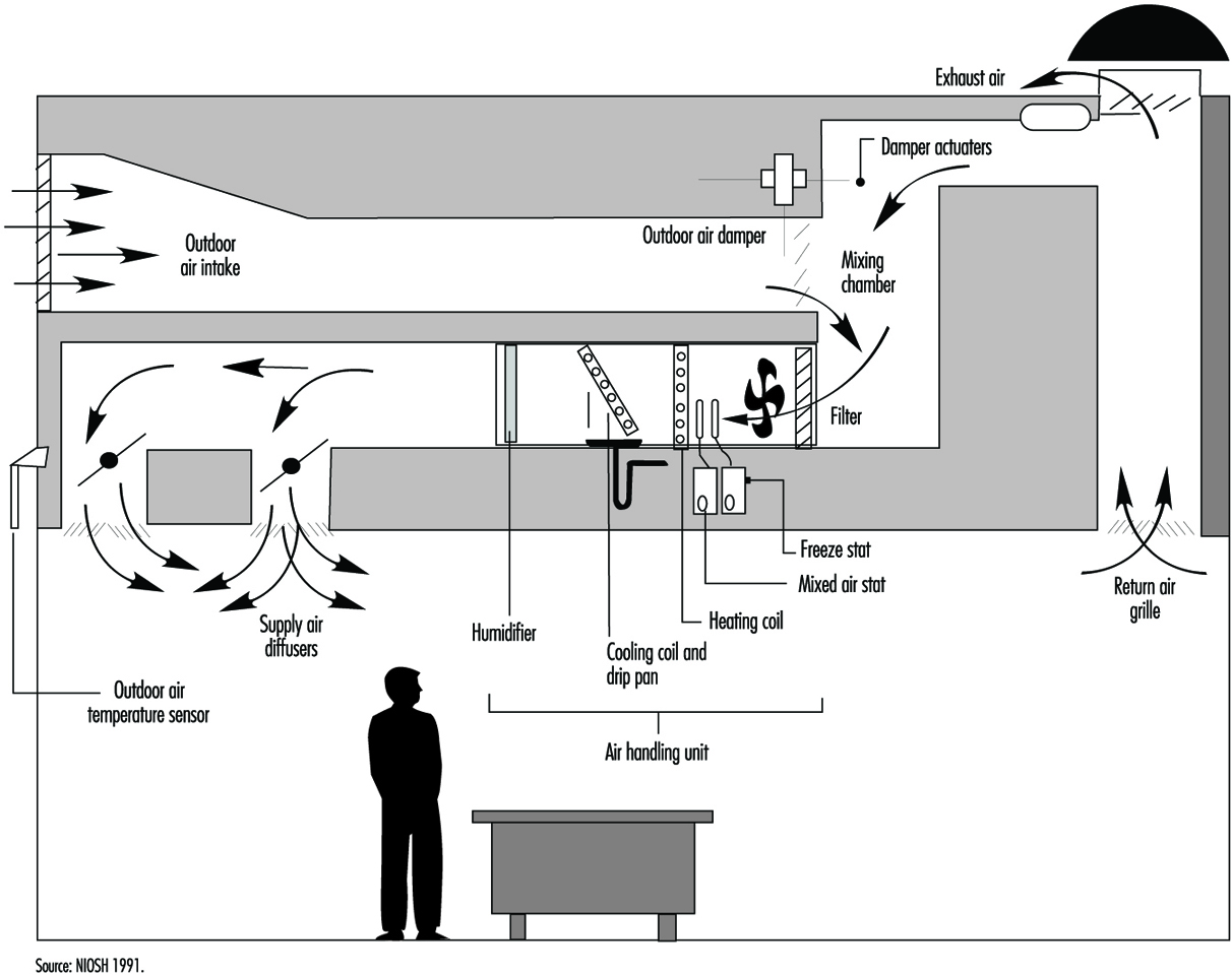
The basic elements of all air-conditioning systems are (see also figure 4):
- Units to retain solid matter, usually bag filters or electrostatic precipitators.
- Air heating or cooling units: heat is exchanged in these units by thermal exchange with cold water or refrigerating liquids, by forced ventilation in the summer and by heating with electrical coils or by combustion in the winter.
- Units to control humidity: in winter humidity can be added by directly injecting water vapour or by direct water evaporation; in the summer it can be removed by refrigerated coils that condense excess humidity in the air, or by a refrigerated water system in which moist air flows through a curtain of drops of water that is colder than the dew point of the moist air.
Figure 4. Simplified schematic of air-conditioning system