- You are here:
-
Home

-
Part XVII. Services and Trade
-
Health Care Facilities and Services
- Healthcare Workers and Infectious Diseases
Elementary and Secondary Schools
Elementary and secondary schools employ many different types of personnel, including teachers, teachers’ aides, administrators, clerical personnel, maintenance personnel, cafeteria personnel, nurses and many others required to keep a school functioning. In general, school personnel face all the potential hazards found in normal indoor and office environments, including indoor air pollution, poor lighting, inadequate heating or cooling, use of office machines, slips and falls, ergonomics problems from poorly designed office furniture and fire hazards. Precautions are the standard ones developed for this type of indoor environment, although building and fire codes usually have specific requirements for schools because of the large number of children present. Other general concerns found in schools include asbestos (especially among custodial and maintenance workers), chipping lead paint, pesticides and herbicides, radon and electromagnetic fields (especially for schools built near high-voltage transmission power lines). Eye and respiratory complaints related to the painting of rooms and the tarring of school roofs while the building is occupied are also a common problem. Painting and tarring should be done when the building is not occupied.
Basic academic duties required of all teachers include: lesson preparation, which can include the development of learning strategies, copying of lecture notes and the making of visual aids such as illustrations, graphs and the like; lecturing, which requires presenting information in an organized fashion that arouses the attention and concentration of students, and can involve the use of blackboards, film projectors, overhead projectors and computers; writing, giving and grading examinations; and individual counselling of students. Most of this instruction takes place in classrooms. In addition, teachers with specialities in science, arts, vocational education, physical education and other areas will conduct much of their teaching in facilities such as laboratories, art studios, theatres, gymnasiums and the like. Teachers may also take students on class trips outside the school to locations such as museums and zoos.
Teachers also have special duties, which can include supervision of students in hallways and the cafeteria; attending meetings with administrators, parents and others; organization and supervision of after-school leisure and other activities; and other administrative duties. In addition, teachers attend conferences and other educational events in order to keep current with their field and advance their career.
There are specific hazards facing all teachers. Infectious diseases such as tuberculosis, measles and chicken pox can easily spread throughout a school. Vaccinations (both of students and teachers), tuberculosis testing and other standard public health measures are essential (see table 1). Overcrowded classrooms, classroom noise, overloaded schedules, inadequate facilities, career advancement questions, job security and general lack of control over working conditions contribute to major stress problems, absenteeism and burnout in teachers. Solutions include both institutional changes to improve working conditions and stress reduction programmes where possible. A growing problem, especially in urban environments, is violence against teachers by students and, sometimes, intruders. In the United States, many secondary-level students, especially in urban schools, carry weapons, including guns. In schools where violence is a problem, organized violence-prevention programmes are essential. Teachers’ aides face many of the same hazards.
Table 1. Infectious diseases affecting day-care workers and teachers.
|
Disease |
Where found |
Mode of transmission |
Comments |
|
Amoebiasis |
Especially tropics and subtropics |
Water and food contaminated with infected faeces |
Use good food and water sanitation. |
|
Chicken pox |
Worldwide |
Generally person- to-person direct contact, but also possible by airborne respiratory droplets |
Chicken pox is more serious in adults than children; risk of birth defects; reportable disease in most countries. |
|
Cytomegalovirus (CMV) |
Worldwide |
Airborne respiratory droplets; contact with urine, saliva or blood |
Highly contagious; risk of birth defects. |
|
Erythema infectiosum (Parvovirus-B- 19) |
Worldwide |
Direct person-to- person contact or airborne respiratory droplets |
Mildly contagious; risk to foetus during pregnancy. |
|
Gastroenteritis, bacterial (Salmonella, Shigella, Campylobacter) |
Worldwide |
Person-to-person transmission, food or water via faecal- oral route |
Use good food and water sanitation; require strict handwashing procedures; reportable disease in most countries. |
|
Gastroenteritis, viral (Rotaviruses) |
Worldwide |
Person-to-person transmission, food or water via faecal- oral route; also by inhalation of dust containing virus |
Use good food and water sanitation. |
|
German measles (rubella) |
Worldwide |
Airborne respiratory droplets; direct contact with infected people |
Risk of birth defects; all children and employees should be vaccinated; reportable disease in most countries. |
|
Giardiasis (intestinal parasite) |
Worldwide, but especially tropics and subtropics |
Contaminated food and water; also possible by person- to-person transmission |
Use good food and water sanitation; reportable disease in most countries. |
|
Hepatitis A virus |
Worldwide, but especially Mediterranean areas and developing countries |
Faecal-oral transmission, especially contaminated food and water; also possible by direct person-to-person contact |
Risk of spontaneous abortions and stillbirths; use good food and water sanitation; reportable disease in most countries. |
|
Hepatitis B virus |
Worldwide, especially Asia and Africa |
Sexual contact, contact of broken skin or mucous membranes with blood or other body fluids |
Higher incidence in institutionalized children (e.g., developmentally disabled); vaccination recommended in high-risk situations; use universal precautions for all exposures to blood and other body fluids; reportable disease in most countries. |
|
Herpes Simplex Type I and II |
Worldwide |
Contact with mucous membranes |
extremely contagious; common in adults and age group 10 to 20 years. |
|
Human Immune Deficiency Virus (HIV) infection |
Worldwide |
Sexual contact, contact of broken skin or mucous membranes with blood or other body fluids |
Leads to Acquired Immune Deficiency Syndrome (AIDS); use universal precautions for all exposures to blood and body fluids (e.g., nosebleeds); anonymous reporting of disease required in most countries. |
|
Infectious mononucleosis Epstein-Barr virus) |
Worldwide |
Airborne respiratory droplets; direct contact with saliva |
Especially common in age group 10 to 20 years. |
|
Influenza |
Worldwide |
Airborne respiratory droplets |
Highly contagious; high-risk individuals should get immunization shots. |
|
Measles |
Worldwide |
Airborne respiratory droplets |
Highly contagious, but for adults mostly a risk to non-immunized individuals working with unvaccinated children; reportable disease in most countries. |
|
Meningococcus meningitis bacterial) |
Mostly tropical Africa and Brazil |
Airborne respiratory droplets, especially close contact |
Reportable disease in most countries. |
|
Mumps |
Worldwide |
Airborne respiratory droplets and contact with saliva |
Highly contagious; exclude infected children; may cause infertility in adults; outbreaks reportable in some countries. |
|
Mycoplasma infections |
Worldwide |
Airborne transmission after close contact |
A major cause of primary atypical pneumonia; mainly affects children aged 5 to 15 years. |
|
Pertussis (whooping cough) |
Worldwide |
Airborne respiratory droplets |
Not as severe in adults; all children under 7 years should be immunized. |
|
Scabies |
Worldwide |
Direct skin-to-skin contact |
Infectious skin disease caused by mites |
|
Streptococcus infections |
Worldwide |
Direct person-to-person contact |
Strep throat, scarlet fever and community-acquired pneumonia are examples of infections. |
|
Tuberculosis (respiratory) |
Worldwide |
Airborne respiratory droplets |
Highly infectious; tuberculosis screening should be conducted for all day care workers; a reportable disease in most countries. |
Teachers in specialized classes can have additional occupational hazards, including chemical exposures, machinery hazards, accidents, electrical hazards, excessive noise levels, radiation and fire, depending on the particular classroom. Figure 1 shows an industrial arts metal shop in a high school, and figure 2 shows a high school science lab with fume hoods and an emergency shower. Table 2 summarizes special precautions, particularly substitution of safer materials, for use in schools. Information on standard precautions can be found in the chapters relevant to the process (e.g., Entertainment and the arts and Safe handling of chemicals).
Figure 1. Industrial arts metal shop in a high school.
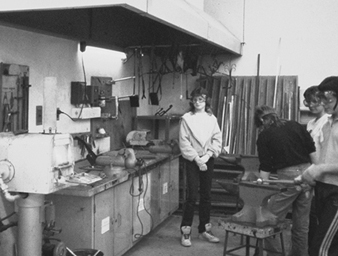
Michael McCann
Figure 2. High school science laboratory with fume hoods and an emergency shower.
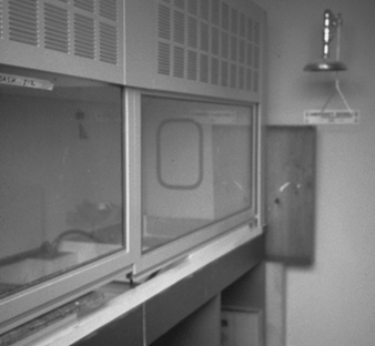
Michael McCann
Table 2. Hazards and precautions for particular classes.
|
Class |
Activity/Subject |
Hazards |
Precautions |
|||
|
Elementary Classes |
||||||
|
Science |
Animal handling
Plants
Chemicals
Equipment
|
Bites and scratches, zoonoses, parasites
Allergies, poisonous plants
Skin and eye problems, toxic reactions, allergies
Electrical hazards, safety hazards |
Allow only live, healthy animals. Handle animals with heavy gloves. Avoid animals which can carry disease-transmitting insects and parasites. Avoid plants which are known to be poisonous or cause allergic reaction. Avoid using toxic chemicals with children. Wear proper personal protective equipment when doing teacher demonstrations with toxic chemicals. Follow standard electrical safety procedures. Ensure all equipment is properly guarded. Store all equipment, tools, etc., properly. |
|||
|
Art |
Painting and drawing
Photography
Textile and fibre arts
Printmaking
Woodworking
Ceramics |
Pigments, solvents
Photochemicals
Dyes
Acids, solvents
Cutting tools
Tools
Glues
Silica, toxic metals, heat, kiln fumes |
Use only non-toxic art materials. Avoid solvents, acids, alkalis, spray cans, chemical dyes, etc. Use only children’s paints. Do not use pastels, dry pigments. Do not do photo processing. Send out film for developing or use Polaroid cameras or blueprint paper and sunlight. Avoid synthetic dyes; use natural dyes such as onion skins, tea, spinach, etc. Use water-based block printing inks. Use linoleum cuts instead of woodcuts. Use soft woods and hand tools only. Use water-based glues. Use wet clay only, and wet mop. Paint pottery rather than using ceramic glazes. Do not fire kiln inside classroom.
|
|||
|
Secondary Classes |
||||||
|
Chemistry |
General
Organic chemistry
Inorganic chemistry
Analytical chemistry
Storage |
Solvents
Peroxides and explosives
Acids and bases
Hydrogen sulphide
Incompatibilities
Flammability |
All school laboratories should have the following: laboratory hood if toxic, volatile chemicals are used; eyewash fountains; emergency showers (if concentrated acids, bases or other corrosive chemicals are present); first aid kits; proper fire extinguishers; protective goggles, gloves and lab coats; proper disposal receptacles and procedures; spill control kit. Avoid carcinogens, mutagens and highly toxic chemicals like mercury, lead, cadmium, chlorine gas, etc.
Use only in laboratory hood. Use least toxic solvents. Do semi-micro- or microscale experiments.
Do not use explosives or chemicals such as ether, which can form explosive peroxides.
Avoid concentrated acids and bases when possible.
Do not use hydrogen sulphide. Use substitutes.
Avoid alphabetical storage, which can place incompatible chemicals in close proximity. Store chemicals by compatible groups.
Store flammable and combustible liquids in approved flammable-storage cabinets. |
|||
|
Biology |
Dissection
Anaesthetizing insects
Drawing of blood
Microscopy
Culturing bacteria |
Formaldehyde
Ether, cyanide
HIV, Hepatitis B
Stains
Pathogens |
Do not dissect specimens preserved in formaldehyde. Use smaller, freeze-dried animals, training films and videotapes, etc.
Use ethyl alcohol for anaesthetization of insects. Refrigerate insects for counting.
Avoid if possible. Use sterile lancets for blood typing under close supervision.
Avoid skin contact with iodine and gentian violet.
Use sterile technique with all bacteria, assuming there could be contamination by pathogenic bacteria. |
|||
|
Physical sciences |
Radioisotopes
Electricity and magnetism
Lasers |
Ionizing radiation
Electrical hazards
Eye and skin damage, electrical hazards |
Use radioisotopes only in “exempt” quantities not requiring a license. Only trained teachers should use these. Develop a radiation safety programme.
Follow standard electrical safety procedures.
Use only low-power (Class I) lasers. Never look directly into a laser beam or pass the beam across face or body. Lasers should have a key lock. |
|||
|
Earth sciences |
Geology
Water pollution
Atmosphere
Volcanoes
Solar observation |
Flying chips
Infection, toxic chemicals
Mercury manometers
Ammonium dichromate
Infrared radiation |
Crush rocks in canvas bag to prevent flying chips. Wear protective goggles.
Do not take sewage samples because of infection risk. Avoid hazardous chemicals in field testing of water pollution.
Use oil or water manometers. If mercury manometers are used for demonstration, have mercury spill control kit.
Do not use ammonium dichromate and magnesium to simulate volcanoes.
Never view sun directly with eyes or through lenses. |
|||
|
Art and Industrial Arts |
All
Painting and drawing
Photography
Textile and fibre arts |
General
Pigments, solvents
Photochemicals, acids, sulphur dioxide
Dyes, dyeing assistants, wax fumes |
Avoid most dangerous chemicals and processes. Have proper ventilation. See also precautions under Chemistry
Avoid lead and cadmium pigments. Avoid oil paints unless cleanup is done with vegetable oil. Use spray fixatives outside.
Avoid colour processing and toning. Have dilution ventilation for darkroom. Have eyewash fountain. Use water instead of acetic acid for stop bath.
Use aqueous liquid dyes or mix dyes in glove box. Avoid dichromate mordants. Do not use solvents to remove wax in batik. Have ventilation if ironing out wax. |
|||
|
|
Papermaking
Printmaking
Woodworking
Ceramics
Sculpture
Jewelry
|
Alkali, beaters
Solvents
Acids, potassium chlorate
Dichromates
Woods and wood dust
Machinery and tools
Noise
Glues
Paints and finishes
Lead, silica, toxic metals, kiln fumes
Silica, plastics resins, dust
Soldering fumes, acids |
Do not boil lye. Use rotten or mulched plant materials, or recycle paper and cardboard. Use large blender instead of more dangerous industrial beaters to prepare paper pulp. Use water-based instead of solvent-based silk screen inks. Clean intaglio press beds nd inking slabs with vegetable oil and dishwashing liquid instead of solvents. Use cut paper stencils instead of lacquer stencils for silk screen printing.
Use ferric chloride to etch copper plates instead of Dutch mordant or nitric acid on zinc plates. If using nitric acid etching, have emergency shower and eyewash fountain and local exhaust ventilation.
Use diazo instead of dichromate photoemulsions. Use citric acid fountain solutions in lithography to replace dichromates.
Have dust collection system for woodworking machines. Avoid irritating and allergenic hardwoods, preserved woods (e.g., chromated copper arsenate treated).Clean up wood dust to remove fire hazards.
Have machine guards. Have key locks and panic button.
Reduce noise levels or wear hearing protectors.
Use water-based glues when possible. Avoid formaldehyde/resorcinol glues, solvent-based glues.
Use water-based paints and finishes. Use shellac based on ethyl alcohol rather than methyl alcohol.
Purchase wet clay. Do not use lead glazes. Buy prepared glazes rather than mixing dry glazes. Spray glazes only in spray booth. Fire kiln outside or have local exhaust ventilation. Wear infrared goggles when looking into hot kiln.
Use only hand tools for stone sculpture to reduce dust levels. Do not use sandstone, granite or soapstone, which might contain silica or asbestos. Do not use highly toxic polyester, epoxy or polyurethane resins. Have ventilation if heating plastics to remove decomposition products. Wet mop or vacuum dusts. Avoid cadmium silver solders and fluoride fluxes. Use sodium hydrogen sulphate rather than sulphuric acid for pickling. Have local exhaust ventilation. |
|||
|
|
Enameling
Lost wax casting
Stained glass
Welding
Commercial art |
Lead, burns, infrared radiation
Metal fumes, silica, infrared radiation, heat
Lead, acid fluxes
Metal fumes, ozone, nitrogen dioxide, electrical and fire hazards
Solvents, photochemicals, video display terminals |
Use only lead-free enamels. Ventilate enameling kiln. Have heat-protective gloves and clothing, and infrared goggles.
Use 50/50 30-mesh sand/plaster instead of cristobalite investments. Have local exhaust ventilation for wax burnout kiln and casting operation. Wear heat-protective clothing and gloves.
Use copper foil technique rather than lead came. Use lead- and antimony-free solders. Avoid lead glass paints. Use acid- and rosin-free soldering fluxes.
Do not weld metals coated with zinc, lead paints, or alloys with hazardous metals (nickel, chromium, etc.). Weld only metals of known composition.
Use double-sided tape instead of rubber cement. Use heptane-based, not hexane rubber cements. Have spray booths for air brushing. Use water-based or alcohol-based permanent markers instead of xylene types. See Photography section for photoprocesses. Have proper ergonomic chairs, lighting, etc., for computers. |
|||
|
Performing Arts |
Theatre
Dance
Music |
Solvents, paints, welding fumes, isocyanates, safety, fire
Acute injuries Repetitive strain injuries
Musculoskeletal injuries (e.g., carpal tunnel syndrome)
Noise
Vocal strain |
Use water-based paints and dyes. Do not use polyurethane spray foams. Separate welding from other areas. Have safe rigging procedures. Avoid pyrotechnics, firearms, fog and smoke, and other hazardous special effects. Fireproof all stage scenery. Mark all trap doors, pits and elevations.
Have a proper dance floor. Avoid full schedules after period of inactivity. Assure proper warm-up before and cool-down after dance activity. Allow sufficient recovery time after injuries.
Use proper sized instruments. Have adequate instrument supports. Allow sufficient recovery time after injuries.
Keep sound levels at acceptable levels. Wear musician’s ear plugs if needed. Position speakers to minimize noise levels. Use sound-absorbing materials on walls. Assure adequate warm-up. Provide proper vocal training and conditioning. |
|||
|
Automotive Mechanics |
Brake drums
Degreasing
Car motors
Welding
Painting |
Asbestos
Solvents
Carbon monoxide
Solvents, pigments |
Do not clean brake drums unless approved equipment is used.
Use water-based detergents. Use parts cleaner
Have tailpipe exhaust.
See above.
Spray paint only in spray booth, or outdoors with respiratory protection.
|
|||
|
Home Economics |
Food and nutrition |
Electrical hazards
Knives and other sharp utensils
Fire and burns
Cleaning products |
Follow standard electrical safety rules.
Always cut away from body. Keep knives sharpened.
Have stove hoods with grease filters that exhaust to outside. Wear protective gloves with hot objects.
Wear goggles, gloves and apron with acidic or basic cleaning products. |
|||
Teachers in special education programmes can sometimes be at greater risk. Examples of hazards include violence from emotionally disturbed students and transmission of infections such as hepatitis A, B and C from institutionalized, developmentally disabled students (Clemens et al. 1992).
Preschool Programmes
Child-care, which involves the physical care and often education of young children, takes many forms in different parts of the world. In many countries where extended families are common, grandparents and other female relatives care for young children when the mother has to work. In countries where the nuclear family and/or single parents predominate and the mother is working, the care of healthy children below school age often occurs in private or public day-care centres or nursery schools outside the home. In many countries - for example, Sweden - these child-care facilities are operated by municipalities. In the United States, most child-care facilities are private, although they are usually regulated by local health departments. An exception is the Head Start Program for preschool children, which is funded by the government.
Staffing of child-care facilities usually depends on the number of children involved and the nature of the facility. For small numbers of children (usually less than 12), the child-care facility might be a home where the children include the preschool children of the caregiver. The staff can include one or more qualified adult assistants to meet staff-to-child ratio requirements. Larger, more formal child-care facilities include day-care centres and nursery schools. The staff members for these are usually required to have more education and can include a qualified director, trained teachers, nursing staff under the supervision of a physician, kitchen staff (nutrition specialists, food service managers and cooks) and other personnel, such as transportation staff and maintenance staff. The premises of the day-care centre should have such amenities as an outdoor play area, cloakroom, reception area, indoor classroom and play area, kitchen, sanitary facilities, administrative rooms, laundry room and so on.
Staff duties include supervision of children in all their activities, changing diapers of infants, emotional nurturing of the children, teaching, food preparation and service, recognition of signs of illness and/or safety hazards and many other functions.
Day-care workers face many of the same hazards found in normal indoor environments, including indoor air pollution, poor lighting, inadequate temperature control, slips and falls and fire hazards. (See the article “Elementary and Secondary Schools”.) Stress (often resulting in burnout) and infections, however, are the major hazards for day-care workers. The lifting and carrying of children and exposure to possibly hazardous art supplies are other hazards.
Stress
Causes of stress in day-care workers include: high responsibility for the welfare of children without adequate pay and recognition; a perception of being unskilled even though many day-care workers have above-average education; image problems due to highly publicized incidents of day-care workers mistreating and abusing children, which have resulted in innocent day-care workers being fingerprinted and treated as potential criminals; and poor working conditions. The latter include low staff-to-child ratios, continual noise, lack of adequate time and facilities for meals and breaks separate from the children and inadequate mechanisms for parent-worker interaction, which can result in unnecessary and possibly unfair pressure and criticism from parents.
Preventive measures to reduce stress in day-care workers include: higher wages and better benefits; higher staff-to-child ratios to allow job rotation, rest breaks, sick leave and better performance, with resulting increase in job satisfaction; establishing formal mechanisms for parent-worker communications and cooperation (possibly including a parent-workers health and safety committee); and improved working conditions, such as adult-size chairs, regular “quiet” times, a separate workers’ break area and so on.
Infections
Infectious diseases, such as diarrhoeal diseases, streptococcal and meningococcal infections, rubella, cytomegalovirus and respiratory infections, are major occupational hazards of day-care workers (see table 1). A study of day-care workers in Belgium found an increased risk of hepatitis A (Abdo and Chriske 1990). Up to 30% of the 25,000 cases of hepatitis A reported annually in the United States have been linked to day-care centres. Some organisms causing diarrhoeal diseases, such as Giardia lamblia, which causes giardiasis, are extremely infectious. Outbreaks can occur in day-care centres serving affluent populations as well as those serving poor areas (Polis et al. 1986). Some infections - for example, German measles and cytomegalovirus - can be especially hazardous for pregnant women, or women planning to have children, because of the risk of birth defects caused by the virus.
Sick children can spread diseases, as can children who have no overt symptoms but are carrying an illness. The most common routes of exposure are faecal-oral and respiratory. Young children usually have poor personal hygiene habits. Hand-to-mouth and toy-to-mouth contact are common. Handling contaminated toys and food is one type of entry route. Some organisms can live on inanimate objects for extended periods ranging from hours to weeks. Food can also be a vector if the food handler has contaminated hands or is ill. Inhalation of airborne respiratory droplets due to sneezing and coughing without protection such as tissues can result in transmission of infections. Such air-borne aerosols can remain suspended in the air for hours.
Day care employees working with children under the age of three years, especially if the children are not toilet-trained, are at greatest risk, particularly when changing and handling soiled diapers which are contaminated by disease-bearing organisms.
Precautions include: convenient facilities for handwashing; regular handwashing by children and staff members; changing diapers in designated areas which are regularly disinfected; disposal of soiled diapers in closed, plastic-lined receptacles which are emptied frequently; separating food preparation areas from other areas; frequent washing of toys, play areas, blankets and other items that could become contaminated; good ventilation; adequate staff-to-child ratios to allow proper implementation of a hygiene programme; a policy of excluding, isolating or restricting sick children, depending on the illness; and adequate sick-leave policies to allow sick day-care workers to stay home.
Adapted from Women’s Occupational Health Resource Center 1987
General Profile
Adapted from 3rd edition, “Encyclopaedia of Occupational Health and Safety”.
The scope of the teaching profession extends from the nursery school to the postgraduate institution. Teaching involves not only academic instruction but also scientific, artistic and technical training, in laboratories, art studios and workshops, and physical training on sports grounds and in gymnasia and swimming pools. In most countries almost everyone comes at some time under the influence of the profession, and the teachers themselves have backgrounds as diverse as the subjects taught. Many senior members of the profession also have administrative and managerial duties.
In addition, the development of policies and activities to promote life-long education necessitates a reassessment of the conventional concept of teachers within traditional establishments (schools, universities). Members of the teaching profession carry out their tasks using formal and informal educational methods, in basic and continuous training, in educational establishments and institutions as well as outside them.
Apart from pupils of school age and university students, new kinds of students and trainees are coming forward in ever-increasing numbers in a great many countries: young jobseekers, women wishing to return to the employment market, retired persons, migrant workers, the handicapped, community groups and so on. In particular, we find categories of persons who were formerly excluded from normal educational establishments: illiterates and the handicapped.
There is nothing new in the variety of apprenticeship facilities available, and private self-education has always existed; life-long education has always existed in one form or another. There is, however, one new factor: the growing development of formal life-long educational facilities in places not originally intended as places of education and through new means—for example, in factories, offices and leisure facilities and through associations, mass communication media and assisted self-education. This growth and spread of educational activities has resulted in an increasing number of persons engaged in teaching on a professional or voluntary basis.
Many types of activity falling within the field of education may overlap: teachers, instructors, lecturers, promoters and organizers of educational projects, educational and vocational guidance workers, career advisers, adult education specialists and administrators.
Regarding the membership of the teaching profession as represented in employment markets, one finds that in most countries they make up one of the most significant categories of the salaried workforce.
Recently, the importance of teachers’ trade unions has increased continuously, keeping pace with the ever-increasing number of teachers. The flexibility of their working hours has enabled teachers to play a significant role in the political life of many countries.
A new type of educator - those who are not exactly teachers in the previously held conception of the term - can now be found in many systems, where the school has become a centre for permanent or life-long educational facilities. These are professionals from various sectors, including handicrafts experts, artists and so on, who contribute permanently or occasionally to these educational activities.
Educational establishments are opening their doors to diverse groups and categories, turning more and more towards external and extramural activities. Two major tendencies can be observed in this connection: on the one hand, relations have been established with the industrial workforce, with industrial plants and processes; and on the other, a growing relation has been established with community development, and there is increasing interaction between institutional education and community education projects.
Universities and colleges endeavour to renew teachers’ initial training through refresher training. Apart from specifically pedagogical aspects and disciplines, they provide for educational sociology, economy and anthropology. A trend still facing many obstacles is to have future teachers acquire experience by doing training periods in community settings, in workplaces or in various educational and cultural establishments. The national service, which has become general in certain countries, is a useful experience in the field for future teachers.
The immense investments in communication and information are auspicious for different types of individual or collective self-teaching. The relation between self-teaching and teaching is an emerging problem. The change-over from the autodidactic training of those who had not attended school to the permanent self-teaching of young people and adults has not always been correctly appreciated by educational institutions.
These new educational policies and activities give rise to various problems such as hazards and their prevention. Permanent education, which is not limited to school experience, turns various places, such as the community, the workplace, the laboratory and the environment, into training premises. The teachers should be assisted in these activities, and insurance coverage should be provided. In order to prevent hazards, efforts should be made to adapt the various premises for educational activities. There are several instances where schools have been adapted to become open centres for the entire population and have been equipped so as to be not only educational institutions but also places for creative and productive activities and for meetings.
The relationship of teachers and instructors with these various periods in the lives of trainees and students, such as leisure time, working time, family life and the duration of apprenticeships, also requires a considerable effort as regards information, research and adaptation.
Relations between teachers and students’ families are also on the increase; sometimes members of families occasionally attend lectures or classes at the school. Dissimilarities between family models and educational models necessitate a great effort from teachers to reach mutual understanding from the psychological, sociological and anthropological standpoint. Family models influence the behaviour pattern of some students, who can experience sharp contradictions between family training and behavioural models and norms prevailing in the school.
However great the variety, all teaching has certain common characteristics: the teacher not only instructs in specific knowledge or skills but also seeks to convey a way of thought; he or she has to prepare the pupil for the next stage of development and stimulate the pupil’s interest and participation in the process of learning.
Silicon Semiconductor Manufacturing
Process Overview
The description of silicon semiconductor device processing, either discrete devices (a semiconductor containing only one active device, such as a transistor) or ICs (interconnected arrays of active and passive elements within a single semiconductor substrate capable of performing at least one electronic circuit function), involves numerous highly technical and specific operations. The intent of this description is to provide a basic framework and explanation of the primary component steps utilized in fabricating a silicon semiconductor device and the associated environmental, health and safety (EHS) issues.
The fabrication of an IC involves a sequence of processes that may be repeated many times before a circuit is complete. The most popular ICs use 6 or more masks to complete patterning processes, with 10 to 24 masks being typical. The manufacture of a microcircuit begins with an ultra-high purity silicon wafer 4 to 12 inches in diameter. Perfectly pure silicon is almost an insulator, but certain impurities, called dopants, added in amounts of from 10 to 100 parts per million, make silicon conduct electricity.
An integrated circuit can consist of millions of transistors (also diodes, resistors and capacitors) made of doped silicon, all connected by the appropriate pattern of conductors to create the computer logic, memory or other type of circuit. Hundreds of microcircuits can be made on one wafer.
Six major fabrication processing steps are universal to all silicon semiconductor devices: oxidation, lithography, etching, doping, chemical vapour deposition and metallization. These are followed by assembly, testing, marking, packing and shipping.
Oxidation
Generally, the first step in semiconductor device processing involves the oxidation of the exterior surface of the wafer to grow a thin layer (about one micron) of silicon dioxide (SiO2). This primarily protects the surface from impurities and serves as a mask for the subsequent diffusion process. This ability to grow a chemically stable protective wafer of silicon dioxide on silicon makes silicon wafers the most widely used semiconductor substrate.
Oxidation, commonly called thermal oxidation, is a batch process which takes place in a high-temperature diffusion furnace. The protective silicon dioxide layer is grown in atmospheres containing either oxygen (O2) (dry oxidation) or oxygen combined with water vapour (H2O) (wet oxidation). The temperatures in the furnace range from 800 to 1,300oC. Chlorine compounds in the form of hydrogen chloride (HCl) may also be added to help control unwanted impurities.
The tendency in newer fabrication facilities is towards vertical oxidation furnaces. Vertical furnaces better address the need for greater contamination control, larger wafer size and more uniform processing. They allow a smaller equipment footprint that conserves precious cleanroom floor space.
Dry oxidation
Silicon wafers to be oxidized are first cleaned, using a detergent and water solution, and solvent rinsed with xylene, isopropyl alcohol or other solvents. The cleaned wafers are dried, loaded into a quartz wafer holder called a boat and loaded into the operator end (load end) of the quartz diffusion furnace tube or cell. The inlet end of the tube (source end) supplies high-purity oxygen or oxygen/nitrogen mixture. The “dry” oxygen flow is controlled into the quartz tube and assures that an excess of oxygen is available for the growth of silicon dioxide on the silicon wafer surface. The basic chemical reaction is:
Si + O2 → SiO2
Wet oxidation
Four methods of introducing water vapour are commonly used when water is the oxidizing agent—pyrophoric, high-pressure, bubbler and flash. The basic chemical reactions are:
Pyrophoric and high pressure: Si + 2O2 + 2 H2 → SiO2 + 2H2O
Flash and bubbler: Si + 2H2O → SiO2 + 2H2
Pyrophoric oxidation involves the introduction and combustion of a hydrogen/oxygen gas mixture. Such systems are generally called burnt hydrogen or torch systems. Water vapour is produced when proper amounts of hydrogen and oxygen are introduced at the inlet end of the tube and allowed to react. The mixture must be controlled precisely to guarantee proper combustion and prevent the accumulation of explosive hydrogen gas.
High-pressure oxidation (HiPox) is technically called a water pyrosynthesis system and generates water vapour through the reaction of ultra-pure hydrogen and oxygen. The steam is then pumped into a high-pressure chamber and pressurized to 10 atmospheres, which accelerates the wet oxidation process. De-ionized water may also be used as a steam source.
In bubbler oxidation de-ionized water is placed in a container called a bubbler and maintained at a constant temperature below its boiling point of 100°C through the use of a heating mantle. Nitrogen or oxygen gas enters the inlet side of the bubbler, becomes saturated with water vapour as it rises through the water, and exits through the outlet into the diffusion furnace. Bubbler systems appear to be the most widely used method of oxidation.
In flash oxidation de-ionized water is dripped continuously into the heated bottom surface of a quartz container and the water evaporates rapidly once it hits the hot surface. Nitrogen or oxygen carrier gas flows over the evaporating water and carries the water vapour into the diffusion furnace.
Lithography
Lithography, also known as photolithography or simply masking, is a method of accurately forming patterns on the oxidized wafer. The microelectronic circuit is built up layer by layer, each layer receiving a pattern from a mask prescribed in circuit design.
The printing trades developed the true antecedents of today’s semiconductor device microfabrication processes. These developments relate to the manufacture of printing plates, usually of metal, on which removal of material through chemical etching produces a surface relief pattern. This same basic technique is used in producing master masks used in the fabrication of each layer of processing of a device.
Circuit designers digitize the basic circuitry of each layer. This computerized schematic allows quick generation of the mask circuitry and facilitates any changes that may be needed. This technique is known as computer-aided design (CAD). Utilizing powerful computer algorithms, these on-line design systems permit the designer to lay out and modify the circuitry directly on video display screens with interactive graphic capabilities.
The final drawing, or mask, for each layer of circuitry is created by a computer-driven photoplotter, or pattern generator. These photoplotted drawings are then reduced to the actual size of the circuit, a master mask produced on glass with chrome relief, and reproduced on a work plate which serves for either contact or projection printing on the wafer.
These masks delineate the pattern of the conducting and insulating areas which are transferred to the wafer through photolithography. Most companies do not produce their own masks, but utilize those furnished by a mask producer.
Cleaning
The need for a particulate- and contamination-free exterior wafer surface requires frequent cleaning. The major categories are:
- de-ionized water and detergent scrubbing
- solvent: isopropyl alcohol (IPA), acetone, ethanol, terpenes
- acid: hydrofluoric (HF), sulphuric (H2SO4) and hydrogen peroxide (H2O2), hydrochloric (HCl), nitric (HNO3) and mixtures
- caustic: ammonium hydroxide (NH4OH).
Resist application
Wafers are coated with a resist material of solvent-based polymer and rapidly rotated on a spinner, which spreads a thin uniform layer. The solvents then evaporate, leaving a polymeric film. All resist materials depend on (primarily ultraviolet) radiation-induced changes in the solubility of a synthetic organic polymer in a selected developer rinse. Resist materials are classified as either negative or positive resists, depending on whether the solubility in the developer decreases (negative) or increases (positive) upon exposure to radiation. Table 1 identifies the component makeup of various photoresist systems.
Table 1. Photoresist systems
|
Ultraviolet |
|||
|
Near (350–450 nm) |
Negative |
PB |
Azide base aliphatic rubber (isoprene) |
|
Positive |
PB |
Ortho-diazoketone |
|
|
Deep (200–250 nm) |
Primarily |
||
|
Electron-beam (about 100 nm) |
|||
|
Negative |
PB |
Copolymer-ethyl acrylate and glycidyl methacrylate (COP) |
|
|
Positive |
PB |
Polymethylmethacrylate, polyfluoralkylmethacrylate, polyalkylaldehyde, poly-cyano ethylacrylate |
|
|
X ray (0.5–5 nm) |
|||
|
Negative |
PB |
Copolymer-ethyl acrylate and glycidyl methacrylate (COP) |
|
|
Positive |
PB |
Polymethylmethacrylate, ortho-diazoketone, poly |
|
PB = polymer base; S = solvent; D = developer.
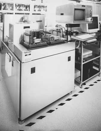
Since most photoresists are ultraviolet (UV) light sensitive, the processing area is lit with special yellow lights lacking sensitive UV wavelengths (see figure 1).
Figure 1. Photolithographic “Yellow room” equipment
Negative and positive UV resists are primarily in use in the industry. E-beam and x-ray resists, however, are gaining in market share because of their higher resolutions. Health concerns in lithography are primarily caused by potential reproductive hazards associated with selected positive resists (e.g., ethylene glycol monoethyl ether acetate as a carrier) that are currently being phased out by the industry. Occasional odours from the negative resists (e.g., xylene) also result in employee concerns. Because of these concerns, a great deal of time is spent by semiconductor industry industrial hygienists sampling photoresist operations. While this is useful in characterizing these operations, routine exposures during spinner and developer operations are typically less than 5% of the airborne standards for occupational exposure for the solvents used in the process (Scarpace et al. 1989).
A 1 hour exposure to ethylene glycol monoethyl ether acetate of 6.3 ppm was found during the operation of a spinner system. This exposure was primarily caused by poor work practices during the maintenance operation (Baldwin, Rubin and Horowitz 1993).
Drying and pre-baking
After the resist has been applied, the wafers are moved on a track or manually moved from the spinner to a temperature-controlled oven with a nitrogen atmosphere. A moderate temperature (70 to 90°C) causes the photoresist to cure (soft bake) and the remaining solvents to evaporate.
To ensure adhesion of the resist layer to the wafer, a primer, hexamethyldisilizane (HMDS), is applied to the wafer. The primer ties up molecular water on the surface of the wafer. HMDS is applied either directly in an immersion or spin-on process or through a vapour prime that offers process and cost advantages over the other methods.
Mask aligning and exposure
The mask and wafer are brought close together using a precise piece of optical/mechanical equipment, and the image on the mask is aligned to any pattern already existing in the wafer beneath the layer of photoresist. For the first mask, no alignment is necessary. In older technologies, alignment for successive layers is made possible by the use of a biscope (dual lens microscope) and precision controls for positioning the wafer with respect to the mask. In newer technologies alignment is done automatically using reference points on the wafers.
Once the alignment is done, a high-intensity ultraviolet mercury vapour or arc lamp source shines through the mask, exposing the resist in places not protected by opaque regions of the mask.
The various methods of wafer alignment and exposure include UV flood exposure (contact or proximity), UV exposure through projection lens for reduction (projection), UV step and repeat reduction exposure (projection), x-ray flood (proximity) and electron beam scan exposure (direct writing). The primary method in use involves UV exposure from mercury vapour and arc lamps through proximity or projection aligners. The UV resists are either designed to react to a broad spectrum of UV wavelengths, or they are formulated to react preferentially to one or more of the main spectrum lines emitted from the lamp (e.g., g-line at 435 nm, h-line at 405 nm and i-line at 365 nm).
The predominant wavelengths of UV light currently used in photomasking are 365 nm or above, but UV lamp spectra also contain significant energy in the wavelength region of health concern, the actinic region below 315 nm. Normally, the intensity of the UV radiation escaping from the equipment is less than both what is present from sunlight in the actinic region and the standards set for occupational exposure to UV.
Occasionally during maintenance, the alignment of the UV lamp requires that it be energized outside the equipment cabinet or without normal protective filters. Exposure levels during this operation can exceed occupational exposure limits, but standard cleanroom attire (e.g., smocks, vinyl gloves, face masks and polycarbonate safety glasses with UV inhibitor) is usually adequate to attenuate the UV light to below exposure limits (Baldwin and Stewart 1989).
While the predominant wavelengths for ultraviolet lamps used in photolithography are 365 nm or above, the quest for smaller features in advanced ICs is leading to the use of exposure sources with smaller wavelengths, such as deep UV and x rays. One new technology for this purpose is the use of krypton-fluoride excimer lasers used in steppers. These steppers use a wavelength of 248 nm with high laser power outputs. However, enclosures for these systems contain the beam during normal operation.
As with other equipment containing high-power laser systems used in semiconductor manufacturing, the main concern is when interlocks for the system must be defeated during beam alignment. High-powered lasers are also one of the most significant electrical hazards in the semiconductor industry. Even after power is off, a significant shock potential exists within the tool. Controls and safety design considerations for these systems are covered by Escher, Weathers and Labonville (1993).
One advanced-technology exposure source used in lithography is x rays. Emission levels from x-ray lithography sources may result in dose rates approaching 50 millisieverts (5 rems) per year in the centre of the equipment. Restricting access to areas inside the shielded wall is recommended to minimize exposure (Rooney and Leavey 1989).
Developing
During the development step the unpolymerized areas of the resist are dissolved and removed. Solvent-based developer is applied to the resist-covered wafer surface by either immersion, spraying or atomization. Developer solutions are identified in table 1. A solvent rinse (n-butyl acetate, isopropyl alcohol, acetone, etc.) is usually applied following the developer to remove any residual material. The resist remaining after developing protect the individual layers during subsequent processing.
Baking
After aligning, exposing and developing the resist, the wafers then move to another temperature-controlled oven with a nitrogen atmosphere. The higher-temperature oven (120 to 135°C) causes the photoresist to cure and fully polymerize on the wafer surface (hard bake).
Photoresist stripping
The developed wafer is then selectively etched using wet or dry chemicals (see “Etching” below). The remaining photoresist must be stripped from the wafer prior to further processing. This is done either by using wet chemical solutions in temperature-controlled baths or through the use of a plasma asher or dry chemical. Table 2 identifies both wet and dry chemical constituents. A discussion of dry chemical plasma etching—using the same equipment and principles of operation as plasma ashing—follows.
Table 2. Photoresist strippers
Wet chemical
Acid
Sulphuric (H2SO4) and chromic (CrO3)
Sulphuric (H2SO4) and ammonium persulphate ((NH4)2S2O8)
Sulphuric (H2SO4) and hydrogen peroxide (H2O2)
Organics
Phenols, sulphuric acids, trichlorobenzene, perchloroethylene
Glycol ethers, ethanolamine, triethanolamine
Sodium hydroxide and silicates (positive resist)
Dry chemical
Plasma ashing (stripping)
RF (radio frequency) power source—13.56 MHz or 2,450 MHz frequency
Oxygen (O2) source gas
Vacuum pump systems
—Oil lubricated with liquid nitrogen trap (old technology)
—Lubricated with inert perfluoropolyether fluids (newer technology)
—Dry pump (newest technology)
Etching
Etching removes layers of silicon dioxide (SiO2), metals and polysilicon, as well as resists, according to the desired patterns delineated by the resist. The two major categories of etching are wet and dry chemical. Wet etching is predominantly used and involves solutions containing the etchants (usually an acid mixture) at the desired strengths, which react with the materials to be removed. Dry etching involves the use of reactive gases under vacuum in a highly energized chamber, which also removes the desired layers not protected by resist.
Wet chemical
The wet chemical etching solutions are housed in temperature-controlled etch baths made of polypropylene (poly-pro), flame-resistant polypropylene (FRPP) or polyvinyl chloride (PVC). The baths generally are equipped with either ring-type plenum exhaust ventilation or slotted exhaust at the rear of the wet chemical etch station. Vertical laminar flow hoods supply uniformly filtered particulate-free air to the top surface of the etch baths. Common wet etchant chemical solutions are presented in table 3, in relation to the surface layer being etched.
Table 3. Wet chemical etchants
|
Material to etch |
Etchants |
|
|
Silicon |
||
|
Polycrystalline silicon (Si) |
Hydrofluoric, nitric, acetic acids and iodine |
|
|
Silicon dioxide (SiO2) |
Buffered oxide etch (BOE) - Hydrofluoric and |
|
|
Silicon nitride (Si3N4) |
Phosphoric and hydrofluoric acids |
|
|
CVD Oxide or Pad Etch |
Ammonium fluoride, acetic and hydrofluoric acids |
|
|
Metals |
||
|
Aluminium (Al) |
Phosphoric, nitric, acetic and hydrochloric acids |
|
|
Chromium-Nickel (Cr/Ni) |
Ceric ammonium nitrate and nitric acid |
|
|
Gold (Au) |
Hydrochloric and nitric acids (aqua regia) |
|
|
Silver (Ag) |
Ferric nitrate (FeNO3) and ethylene glycol |
|
|
Compound |
Formula |
Standard concentration (%) |
|
Acetic acid |
CH3COOH |
36 |
|
Ammonium fluoride |
NH4F |
40 |
|
Glacial acetic acid |
CH3COOH |
99.5 |
|
Hydrochloric acid |
HCl |
36 |
|
Hydrofluoric acid |
HF |
49 |
|
Nitric acid |
HNO3 |
67 |
|
Phosphoric acid |
H3PO4 |
85 |
|
Potassium hydroxide |
KOH |
50 or 10 |
|
Sodium hydroxide |
NaOH |
50 or 10 |
|
Sulphuric acid |
H2SO4 |
96 |
Vertically mounted flow supply hoods, when used in conjunction with splash shields and exhaust ventilation, can create areas of air turbulence within the wet chemical etch station. As a result, a decrease is possible in the effectiveness of the local exhaust ventilation in capturing and routing fugitive air contaminants from the etch baths in use.
The main concern with wet etching is the possibility of skin contact with the concentrated acids. While all the acids used in etching can cause acid burns, exposure to hydrofluoric acid (HF) is of particular concern. The lag time between skin contact and pain (up to 24 hours for solutions less than 20% HF and 1 to 8 hours for 20 to 50% solutions) can result in delayed treatment and more severe burns than expected (Hathaway et al. 1991).
Historically acid burns have been a particular problem within the industry. However, the incidence of skin contact with acids have been reduced in recent years. Some of this reduction was caused by product-related improvements in the etch process, such as the shift to dry etching, the use of more robotics and the installation of chemical dispense systems. The reduction in the rate of acid burns may also be attributed to better handling techniques, greater use of personal protective equipment, better designed wet decks and better training—all of which require continued attention if the rate is to decline further (Baldwin and Williams 1996).
Dry chemical
Dry chemical etching is an area of growing interest and usage due to its ability to better control the etching process and reduce contamination levels. Dry chemical processing effectively etches desired layers through the use of chemically reactive gases or through physical bombardment.
Chemically reactive plasma etching systems have been developed which can effectively etch silicon, silicon dioxide, silicon nitride, aluminium, tantalum, tantalum compounds, chromium, tungsten, gold and glass. Two kinds of plasma etching reactor systems are in use—the barrel, or cylindrical, and the parallel plate, or planar. Both operate on the same principles and primarily vary in configuration only.
A plasma is similar to a gas except that some of the atoms or molecules of the plasma are ionized and may contain a substantial number of free radicals. The typical reactor consists of a vacuum reactor chamber containing the wafer, usually made of aluminium, glass or quartz; a radio-frequency (RF) energy source—usually at 450 kHz, 13.56 MHz or 40.5 MHz and a control module to control processing time, composition of reactant gas, flow rate of gas and RF power level. In addition, an oil-lubricated (older technology) or dry (newer technology) roughing pump vacuum source is in line with the reactor chamber. Wafers are loaded into the reactor, either individually or in cassettes, a pump evacuates the chamber and the reagent gas (usually carbon tetrafluoride) is introduced. Ionization of the gas forms the etching plasma, which reacts with the wafers to form volatile products which are pumped away. The introduction of fresh reactant gas into the chamber maintains etching activity. Table 4 identifies the materials and plasma gases in use for etching various layers.
Table 4. Plasma etching gases and etched materials
|
Material |
Gas |
|
Silicon |
|
|
Polysilicon (polySi) and Silicon |
CF + O2, CCl4 or CF3Cl, CF4 and HCl |
|
Silicon dioxide (SiO2) |
C2F6, C3F8, CF4, SiF4, C5F12, CHF3, CCl2F2, SF6, HF |
|
Silicon nitride (Si3N4) |
CF4 + Ar, CF4 + O2, CF4 + H2 |
|
Metals |
|
|
Aluminium (Al) |
CCl4 or BCl3 + He or Ar |
|
Chromium (Cr) |
CCl4 |
|
Chromium oxide (CrO3) |
Cl2 + Ar or CCl4 + Ar |
|
Gallium arsenide (GaAs) |
CCl2F2 |
|
Vanadium (V) |
CF4 |
|
Titanium (Ti) |
CF4 |
|
Tantulum (Ta) |
CF4 |
|
Molybdenum (Mo) |
CF4 |
|
Tungsten (W) |
CF4 |
Another method that currently is being developed for etching is microwave downstream. It uses a high-power-density microwave discharge to produce metastable atoms with long lifetimes that etch material almost as if it were immersed in acid.
Physical etching processes are similar to sandblasting in that argon gas atoms are used to physically bombard the layer to be etched. A vacuum pump system is used to remove dislocated material. Reactive ion etching involves a combination of chemical and physical dry etching.
The sputtering process is one of ion impact and energy transfer. Sputter etching incorporates a sputtering system, where the wafer to be etched is attached to a negative electrode or target in a glow-discharge circuit. Material sputters from the wafer by bombardment with positive ions, usually argon, and results in the dislocation of the surface atoms. Power is provided by an RF source at 450 kHz frequency. An in-line vacuum system is used for pressure control and reactant removal.
Ion-beam etching and milling is a gentle etching process which uses a beam of low-energy ions. The ion-beam system consists of a source to generate the ion beam, a work chamber in which the etching or milling occurs, fixturing with a target plate for holding the wafers in the ion beam, a vacuum pump system, supporting electronics and instruments. The ion beam is extracted from an ionized gas (argon or argon/oxygen) or plasma, which is created by the electrical discharge. The discharge is obtained by applying a voltage between an electron-emitting hot-filament cathode and an anode cylinder located in the outer diameter of the discharge region.
Ion-beam milling is done in the low-energy range of ion bombardment, where only surface interactions occur. These ions, usually in the 500 to 1,000 eV range, strike a target and sputter off surface atoms by breaking the forces bonding the atom to its neighbour. Ion-beam etching is done in a slightly higher energy range, which involves a more dramatic dislocation of surface atoms.
Reactive ion etching (RIE) is a combination of physical sputtering and chemical reactive species etching at low pressures. RIE uses ion bombardment to achieve directional etching and also a chemically reactive gas, carbon tetrafluoride (CF4) or carbon tetrachloride (CCl4), to maintain good etched layer selectivity. A wafer is placed in a chamber with an atmosphere of chemically reactive gas compound at a low pressure of about 0.1 torr (1.3 x 10⁻⁴ atmosphere). An electrical discharge creates a plasma of reactive “free radicals” (ions) with an energy of a few hundred electron volts. The ions strike the wafer surface vertically, where they react to form volatile species that are removed by a low-pressure in-line vacuum system.
Dry etchers sometimes have a cleaning cycle that is used to remove deposits that accumulate on the inside of the reaction chambers. Parent compounds used for the cleaning cycle plasmas include nitrogen trifluoride (NF3), hexafluoroethane (C2F6) and octafluoropropane (C3F8).
These three gases used in the cleaning process, and many of the gases used in etching, are a cornerstone to an environmental issue facing the semiconductor industry which surfaced in the mid-1990s. Several of the highly fluorinated gases were identified as having significant global warming (or greenhouse effect) potential. (These gases are also referred to as PFCs, perfluorinated compounds.) The long atmospheric lifetime, high global warming potential and significant increased usage of PFCs like NF3, C2F6, C3F8, CF4, trifluoromethane (CHF3) and sulphur hexafluoride (SF6) had the semiconductor industry focus on ways to reduce their emissions.
Atmospheric emissions of PFCs from the semiconductor industry have been due to poor tool efficiency (many tools consumed only 10 to 40% of the gas used) and inadequate air emission abatement equipment. Wet scrubbers are not effective in removing PFCs, and tests on many combustion units found poor destruction efficiencies for some gases, especially CF4. Many of these combustion units broke down C2F6 and C3F8 into CF4. Also, the high cost of ownership for these abatement tools, their power demand, their release of other global warming gases and their combustion by-products of hazardous air pollutants indicated combustion abatement was not a suitable method for controlling PFC emissions.
Making process tools more efficient, identifying and developing more environmentally friendly alternatives to these dry etchant gases and recovery/recycling of the exhaust gases have been the environmental emphases associated with dry etchers.
The major occupational hygiene emphasis for dry etchers has been on potential exposures to maintenance personnel working on the reaction chambers, pumps and other associated equipment that may contain reaction product residues. The complexity of plasma metal etchers and the difficulty in characterizing the odours associated with their maintenance has made them the subject of many investigations.
The reaction products formed in plasma metal etchers are a complex mixture of chlorinated and fluorinated compounds. The maintenance of metal etchers often involves short-duration operations that generate strong odours. Hexachloroethane was found to be the major cause of odour in one type of aluminium etcher (Helb et al. 1983). In another, cyanogen chloride was the main problem: exposure levels were 11 times the 0.3 ppm occupational exposure limit (Baldwin 1985). In still other types of etchers, hydrogen chloride is associated with the odour; maximum exposure measured was 68 ppm (Baldwin, Rubin and Horowitz 1993). For additional information on the subject see Mueller and Kunesh (1989).
The complexity of the chemistries present in metal etcher exhausts has led researchers to develop experimental methods for investigating the toxicity of these mixtures (Bauer et al. 1992a). Application of these methods in rodent studies indicates certain of these chemical mixtures are suspected mutagens (Bauer et al. 1992b) and suspected reproductive toxins (Schmidt et al. 1995).
Because dry etchers operate as closed systems, chemical exposure to the operators of the equipment typically does not occur while the system is closed. One rare exception to this is when the purge cycle for older batch etchers is not long enough to adequately remove the etchant gases. Brief but irritating exposures to fluorine compounds that are below the detection limit for typical industrial hygiene monitoring procedures have been reported when the doors to these etchers are opened. Normally this can be corrected by simply increasing the length of the purge cycle prior to opening the etch chamber door.
The primary concern for operator exposure to RF energy comes during plasma etching and ashing (Cohen 1986; Jones 1988). Typically, the leakage of RF energy can be caused by:
- misaligned doors
- cracks and holes in the cabinets
- metal tables and electrical cables acting as antennae due to improper grounding of the etcher
- no attenuating screen in the viewing window of the etcher (Jones 1988; Horowitz 1992).
RF exposure can also occur during the maintenance of etchers, particularly if the equipment cabinet has been removed. An exposure of 12.9 mW/cm2 was found at the top of an older model plasma etcher with the cover removed for maintenance (Horowitz 1992). The actual RF radiation leakage in the area where the operator stands was typically less than 4.9 mW/cm2.
Doping
The formation of an electrical junction or boundary between p and n regions in a single crystal silicon wafer is the essential element for the functioning of all semiconductor devices. Junctions permit current to flow in one direction much more easily than in the other. They provide the basis for diode and transistor effects in all semiconductors. In an integrated circuit, a controlled number of elemental impurities or dopants, must be introduced into selected etched regions of the silicon substrate, or wafer. This can be done either by diffusion or ion implantation techniques. Regardless of the technique used, the same types or dopants are used for the production of semiconductor junctions. Table 5 identifies the main components used for doping, their physical state, electrical type (p or n) and the primary junction technique in use—diffusion or ion implantation.
Table 5. Junction formation dopants for diffusion and ion implantation
|
Element |
Compound |
Formula |
State |
Technique |
|
n-type |
||||
|
Antimony |
Antimony trioxide |
Sb2O3 |
Solid |
Diffusion |
|
Arsenic |
Arsenic trioxide |
As2O3 |
Solid |
Diffusion |
|
Phosphorus |
Phosphorus pentoxide |
P2O5 |
Solid |
Diffusion |
|
p-type |
||||
|
Boron |
Boron nitride |
BN |
Solid |
Diffusion |
Routine chemical exposures to operators of both diffusion furnaces and ion implanters are low—typically less that the detection limit of standard occupational hygiene sampling procedures. Chemical concerns with the process centre on the possibility of toxic gas releases.
As early as the 1970s, progressive semiconductor manufacturers began installing the first continuous gas-monitoring systems for flammable and toxic gases. The main focus of this monitoring was to detect accidental releases of the most toxic dopant gases with odour thresholds above their occupational exposure limits (e.g., arsine and diborane).
Most industrial hygiene air monitors in the semiconductor industry are used for flammable and toxic gas leak detection. However, some facilities are also using continuous monitoring systems to:
- analyse exhaust duct (stack) emissions
- quantify ambient air concentrations of volatile chemicals
- identify and quantify odours in the fab areas.
The technologies most used in the semiconductor industry for this type of monitoring are colorimetric gas detection (e.g., MDA continuous gas detector), electrochemical sensors (e.g., sensydyne monitors) and Fourier transform infrared (e.g., Telos ACM) (Baldwin and Williams 1996).
Diffusion
Diffusion is a term used to describe the movement of dopants away from regions of high concentration at the source end of the diffusion furnace to regions of lower concentration within the silicon wafer. Diffusion is the most established method of junction formation.
This technique involves subjecting a wafer to a heated atmosphere within the diffusion furnace. The furnace contains the desired dopants in a vapour form and results in creating regions of doped electrical activity, either p or n. The most commonly used dopants are boron for p-type; and phosphorus (P), arsenic (As) or antimony (Sb) for n-type (see table 5).
Typically, wafers are stacked in a quartz carrier or boat and placed in the diffusion furnace. The diffusion furnace contains a long quartz tube and a mechanism for accurate temperature control. Temperature control is extremely important, as the rates of diffusion of the various silicon dopants are primarily a function of temperature. The temperatures in use range from 900 to 1,300 oC, depending on the specific dopant and process.
The heating of the silicon wafer to a high temperature allows the impurity atoms to diffuse slowly through the crystal structure. Impurities move more slowly through silicon dioxide than through the silicon itself, enabling the thin oxide pattern to serve as a mask and thereby permitting the dopant to enter silicon only where it is unprotected. After enough impurities have accumulated, the wafers are removed from the furnace and diffusion effectively ceases.
For maximum control, most diffusions are performed in two steps—predeposition and drive in. The predeposit, or diffusion with constant source, is the first step and takes place in a furnace in which the temperature is selected to achieve the best control of impurity amounts. The temperature determines the solubility of the dopant. After a comparatively short predeposit treatment, the wafer is physically moved to a second furnace, usually at a higher temperature, where a second heat treatment drives in the dopant to the desired depth of diffusion in the silicon wafer lattice.
The dopant sources used in the predeposit step are in three distinct chemical states: gas, liquid and solid. Table 5 identifies the various types of diffusion source dopants and their physical states.
Gases are generally supplied from compressed gas cylinders with pressure controls or regulators, shut-off valves and various purging attachments and are dispensed through small-diameter metal tubing.
Liquids are dispensed normally from bubblers, which saturate a carrier gas stream, usually nitrogen, with the liquid dopant vapours, as is described in the section on wet oxidation. Another form of liquid dispensing is through the use of the spin-on dopant apparatus. This entails putting a solid dopant in solution with a liquid solvent carrier, then dripping the solution on the wafer and spinning, in a manner similar to the application of photoresists.
Solid sources may be in the shape of a boron nitride wafer, which is sandwiched between two silicon wafers to be doped and then placed in a diffusion furnace. Also, the solid dopants, in powder or bead form, may be placed in a quartz bomb enclosure (arsenic trioxide), manually dumped in the source end of a diffusion tube or loaded in a separate source furnace in line with the main diffusion furnace.
In the absence of proper controls, arsenic exposures above 0.01 mg/m3 were reported during the cleaning of a deposition furnace (Wade et al. 1981) and during the cleaning of source housing chambers for solid-source ion implanters (McCarthy 1985; Baldwin, King and Scarpace 1988). These exposures occurred when no precautions were taken to limit the amount of dust in the air. However, when residues were kept wet during cleaning, exposures were reduced to far below the airborne exposure limit.
In the older diffusion technologies safety hazards exist during the removal, cleaning and installation of furnace tubes. The hazards include potential cuts from broken quartz ware and acid burns during the manual cleaning. In newer technologies these hazards are lessened by in situ tube cleaning that eliminates much of the manual handling.
Diffusion furnace operators experience the highest routine cleanroom exposure to extremely low-frequency electromagnetic fields (e.g., 50 to 60 hertz) in semiconductor manufacturing. Average exposures greater than 0.5 microteslas (5 milligauss) were reported during actual operation of the furnaces (Crawford et al. 1993). This study also noted that cleanroom personnel working in the vicinity of diffusion furnaces had average measured exposures that were noticeably higher than those of other cleanroom workers. This finding was consistent with point measurements reported by Rosenthal and Abdollahzadeh (1991), who found that diffusion furnaces produced proximity readings (5 cm or 2 inches away) as high as 10 to 15 microteslas, with the surrounding fields falling off more gradually with distance than other cleanroom equipment studied; even at 6 feet away from diffusion furnaces, the reported flux densities were 1.2 to 2 microteslas (Crawford et al. 1993). These emission levels are well below current health-based exposure limits set by the World Health Organization and those set by individual countries.
Ion implantation
Ion implantation is the newer method of introducing impurities elements at room temperature into silicon wafers for junction formation. Ionized dopant atoms (i.e., atoms stripped of one or more of their electrons) are accelerated to a high energy by passing them through a potential difference of tens of thousands of volts. At the end of their path, they strike the wafer and are embedded at various depths, depending on their mass and energy. As in conventional diffusion, a patterned oxide layer or a photoresist pattern selectively masks the wafer from the ions.
A typical ion implantation system consists of an ion source (gaseous dopant source, usually in small lecture bottles), analysis equipment, accelerator, focusing lens, neutral beam trap, scanner process chamber and a vacuum system (normally three separate sets of in-line roughing and oil-diffusion pumps). The stream of electrons is generated from a hot filament by resistance, an arc discharge or cold cathode electron beam.
Generally, after wafers are implanted, a high temperature annealing step (900 to 1,000°C) is performed by a laser beam anneal or pulsed annealing with an electron-beam source. The annealing process helps repair the damage to the exterior surface of the implanted wafer caused by the bombardment of dopant ions.
With the advent of a safe delivery system for arsine, phosphine and boron trifluoride gas cylinders used in ion implanters, the potential for catastrophic release of these gases has been greatly reduced. These small gas cylinders are filled with a compound to which the arsine, phosphine and boron trifluoride are adsorbed. The gases are pulled out of the cylinders by use of a vacuum.
Ion implanters are one of the most significant electrical hazards in the semiconductor industry. Even after power is off, a significant shock potential exists within the tool and must be dissipated prior to working inside the implanter. A careful review of maintenance operations and the electrical hazards is warranted for all newly installed equipment, but especially for ion implanters.
Exposures to hydrides (probably a mixture of arsine and phosphine) as high as 60 ppb have been found during ion implanter cryo-pump maintenance (Baldwin, Rubin and Horowitz 1993). Also, high concentrations of both arsine and phosphine can off-gas from contaminated implanter parts that are removed during preventive maintenance (Flipp, Hunsaker and Herring 1992).
Portable vacuum cleaners with high-efficiency particulate attenuator (HEPA) filters are used to clean arsenic-contaminated work surfaces in ion implantation areas. Exposures above 1,000 μg/m3 were measured when HEPA vacuums were improperly cleaned. HEPA vacuums, when discharging to the workspace, can also efficiently distribute the distinctive, hydride-like odour associated with ion implanter beam line cleaning (Baldwin, Rubin and Horowitz 1993).
While a concern, there have been no published reports of significant dopant gas exposures during oil changes of vacuum pumps used with dopants—possibly because this is usually done as a closed system. The lack of reported exposure may also be a result of low levels of off-gassing of hydrides from the used oil.
The result of a field study where 700 ml of used roughing pump oil from an ion implanter which used both arsine and phosphine was heated only showed detectable concentrations of airborne hydrides in the pump head space when the pump oil exceeded 70oC (Baldwin, King and Scarpace 1988). Since normal operating temperatures for mechanical roughing pumps are 60 to 80oC, this study did not indicate the potential for a significant exposure.
During ion implantation, x rays are formed incidental to the operation. Most implanters are designed with sufficient cabinet shielding (which includes lead sheeting strategically placed around the ion source housing and adjacent access doors) to maintain employee exposure below 2.5 microsieverts (0.25 millirems) per hour (Maletskos and Hanley 1983). However, an older model of implanters was found to have x-ray leakage above 20 microsieverts per hour (μSv/hr) at the unit’s surface (Baldwin, King and Scarpace 1988). These levels were reduced to less than 2.5 μSv/hr after additional lead shielding was installed. Another older model of ion implanter was found to have x-ray leakage around an access door (up to 15 μSv/hr) and at a viewport (up to 3 μSv/hr). Additional lead shielding was added to attenuate possible exposures (Baldwin, Rubin and Horowitz 1993).
In addition to x-ray exposures from ion implanters, the possibility of neutron formation has been postulated if the implanter is operated above 8 million electron volts (MeV) or deuterium gas is used as an ion source (Rogers 1994). However, typically implanters are designed to operate at well below 8 MeV, and deuterium is not commonly used in the industry (Baldwin and Williams 1996).
Chemical vapour deposition
Chemical vapour deposition (CVD) involves the layering of additional material on the silicon wafer surface. CVD units normally operate as a closed system resulting in little or no chemical exposure to the operators. However, brief hydrogen chloride exposure above 5 ppm can occur when certain CVD prescrubbers are cleaned (Baldwin and Stewart 1989). Two broad categories of deposition are in common use—epitaxial and the more general category of non-epitaxial CVD.
Epitaxial chemical vapour deposition
Epitaxial growth is rigidly controlled deposition of a thin single crystal film of a material which maintains the same crystal structure as the existing substrate wafer layer. It serves as a matrix for fabricating semiconductor components in subsequent diffusion processes. Most epitaxial films are grown on substrates of the same material, such as silicon on silicon, in a process referred to as homoepitaxy. Growing layers of different materials on a substrate, such as silicon on sapphire, is called heteroepitaxy IC device processing.
Three primary techniques are used to grow epitaxial layers: vapour phase, liquid phase and molecular beam. Liquid-phase and molecular-beam epitaxy are primarily used in the processing of III-V (e.g., GaAs) devices. These are discussed in the article “III-V semiconductor manufacturing”.
Vapour-phase epitaxy is used to grow a film by the CVD of molecules at a temperature of 900 to 1,300oC. Vapours containing the silicon and controlled amounts of p- or n-type dopants in a carrier gas (usually hydrogen) are passed over heated wafers to deposit doped layers of silicon. The process is generally performed at atmospheric pressure.
Table 6 identifies the four major types of vapour-phase epitaxy, parameters and the chemical reactions taking place.
Table 6. Major categories of silicon vapour-phase epitaxy
|
Parameters |
||
|
Pressure |
Atmospheric |
|
|
Temperature |
900–1300 °C |
|
|
Silicon sources |
Silane (SiH4), silicon tetrachloride (SiCl4), trichlorosilane (SiHCl3), |
|
|
Dopant gases |
Arsine (AsH3), phosphine (PH3), diborane (B2H6) |
|
|
Dopant gas concentration |
≈100 ppm |
|
|
Etchant gas |
Hydrogen chloride (HCl) |
|
|
Etchant gas concentration |
≈1–4% |
|
|
Carrier gases |
Hydrogen (H2), nitrogen (N2) |
|
|
Heating source |
Radio frequency (RF) or infrared (IR) |
|
|
Vapour-phase epitaxy types |
Chemical reactions |
|
|
Hydrogen reduction of silicon tetrachloride |
SiCl4 + 2H2 → Si + 4HCl |
|
|
Pyrolytic decomposition of silane |
SiH4 → Si + 2H2 |
|
|
Hydrogen reduction of trichlorosilane |
SiHCl3 + H2 → Si + 3HCl |
|
|
Reduction of dichlorosilane |
SiH2Cl2 → Si + 2HCl |
|
The deposition sequence normally followed in an epitaxial process involves:
- substrate cleaning—physical scrubbing, solvent degreasing, acid cleaning (sulphuric, nitric and hydrochloric, and hydrofluoric is a common sequence) and drying operation
- wafer loading
- heat up—nitrogen purging and heating to approximately 500 °C, then hydrogen gas is used and RF generators inductively heat wafers
- hydrogen chloride (HCl) etch—usually 1 to 4% concentration of HCl is dispensed to the reactor chamber
- deposition—silicon source and dopant gases are metered in and deposited on wafer surface
- cool down—hydrogen gas switched to nitrogen again at 500°C
- unloading.
Non-epitaxial chemical vapour deposition
Whereas epitaxial growth is a highly specific form of CVD where the deposited layer has the same crystalline structure orientation as the substrate layer, non-epitaxial CVD is the formation of a stable compound on a heated substrate by the thermal reaction or decomposition of gaseous compounds.
CVD can be used to deposit many materials, but in silicon semiconductor processing the materials generally encountered, in addition to epitaxial silicon, are:
- polycrystalline silicon (poly Si)
- silicon dioxide (SiO2—both doped and undoped; p-doped glass)
- silicon nitride (Si3N4).
Each of these materials may be deposited in a variety of ways, and each has many applications.
Table 7 identifies the three major categories of CVD using operating temperature as a mechanism of differentiation.
Table 7. Major categories of silicon chemical vapour deposition (CVD)
|
Parameters |
||||
|
Pressure |
Atmospheric (APCVD) or low pressure (LPCVD) |
|||
|
Temperature |
500–1,100 °C |
|||
|
Silicon and nitride sources |
Silane (SiH4), silicon tetrachloride (SiCl4), ammonia (NH3), nitrous oxide (N20) |
|||
|
Dopant sources |
Arsine (AsH3), phosphine (PH3), diborane (B2H6) |
|||
|
Carrier gases |
Nitrogen (N2), hydrogen (H2) |
|||
|
Heating source |
Cold wall system—radio frequency (RF) or infrared (IR) |
|||
|
CVD type |
Reaction |
Carrier gas |
Temperature |
|
|
Medium temperature (≈ 600–1,100 °C) |
||||
|
Silicon nitride (Si3N4) |
3SiH4 + 4 NH3 → Si3N4 + 12H2 |
H2 |
900–1,100 °C |
|
|
Polysilicon (poly Si) |
SiH4 + Heat → Si + 2H2 |
H2 |
850–1,000 °C |
|
|
Silicon dioxide (SiO2) |
SiH4 + 4CO2 → SiO2 + 4CO + 2H2O |
N2 |
500–900 °C |
|
|
Low temperature (≈<600 C) Silox, Pyrox, Vapox and Nitrox** |
||||
|
Silicon dioxide (SiO2) or p-doped SiO2 |
||||
|
Silox |
SiH4 + 2O2 + Dopant → SiO2 + 2H2O |
N2 |
200–500 °C |
|
|
Pyrox |
SiH4 + 2O2 + Dopant → SiO2 + 2H2O |
N2 |
<600 °C |
|
|
Vapox |
SiH4 + 2O2 + Dopant → SiO2 + 2H2O |
N2 |
<600 °C |
|
|
Silicon nitride (Si3N4) |
||||
|
Nitrox |
3SiH4 + 4NH3 (or N2O*) → Si3N4 + 12H2 |
N2 |
600–700 °C |
|
|
Low temperature plasma enhanced (passivation) (<600°C) |
||||
|
Utilizing radio-frequency (RF) or |
||||
|
Silicon dioxide (SiO2) |
SiH4 + 2O2 → SiO2 + 2H20 |
|||
|
Silicon nitride (Si3N4) |
3SiH4 + 4NH3 (or N2O*) → Si3N4 + 12H2 |
|||
* Note: Reactions are not stoichiometrically balanced.
**Generic, proprietary or trademark names for CVD reactor systems
The following components are found in nearly all the types of CVD equipment:
- reaction chamber
- gas control section
- time and sequence control
- heat source for substrates
- effluent handling.
Basically, the CVD process entails supplying controlled amounts of silicon or nitride source gases, in conjunction with nitrogen and/or hydrogen carrier gases, and a dopant gas if desired, for chemical reaction within the reactor chamber. Heat is applied to provide the necessary energy for the chemical reaction in addition to controlling the surface temperatures of the reactor and wafers. After the reaction is complete, the unreacted source gas plus the carrier gas are exhausted through the effluent handling system and vented to the atmosphere.
Passivation is a functional type of CVD. It involves the growth of a protective oxide layer on the surface of the silicon wafer, generally as the last fabrication step prior to non-fabrication processing. The layer provides electrical stability by isolating the integrated circuit’s surface from electrical and chemical conditions in the environment.
Metallization
After the devices have been fabricated in the silicon substrate, they must be connected together to perform circuit functions. This process is known as metallization. Metallization provides a means of wiring or interconnecting the uppermost layers of integrated circuits by depositing complex patterns of conductive materials, which route electrical energy within the circuits.
The broad process of metallization is differentiated according to the size and thickness of the layers of metals and other materials being deposited. These are:
- thin film—approximate film thickness of one micron or less
- thick film—approximate film thickness of 10 microns or greater
- plating—film thicknesses are variable from thin to thick, but generally thick films.
The most common metals used for silicon semiconductor metallization are: aluminium, nickel, chromium or an alloy called nichrome, gold, germanium, copper, silver, titanium, tungsten, platinum and tantalum.
Thin or thick films may also be evaporated or deposited on various ceramic or glass substrates. Some examples of these substrates are: alumina (96% Al203), beryllia (99% BeO), borosilicate glass, pyroceram and quartz (SiO2).
Thin film
Thin film metallization is often applied through the use of a high-vacuum or partial-vacuum deposition or evaporation technique. The major types of high-vacuum evaporation are electron beam, flash and resistive, while partial-vacuum deposition is primarily done by sputtering.
To perform any type of thin film vacuum metallization, a system usually consists of the following basic components:
- a chamber that can be evacuated to provide a sufficient vacuum for deposition
- a vacuum pump (or pumps) to reduce ambient gases in the chamber
- instrumentation for monitoring the vacuum level and other parameters
- a method of depositing or evaporating the layers of metallizing material.
Electron-beam evaporation, frequently called E beam, uses a focused beamof electrons to heat the metallization material. A high-intensity beam of electrons is generated in a manner similar to that used in a television picture tube. A stream of electrons is accelerated through an electrical field of typically 5 to 10 kV and focused on the material to be evaporated. The focused beam of electrons melts the material contained in a water-cooled block with a large depression called a hearth. The melted material then vaporizes within the vacuum chamber and condenses on the cool wafers as well as on the entire chamber surface. Then standard photoresist, exposure, development and wet or dry etch operations are performed to delineate the intricate metallized circuitry.
Flash evaporation is another technique for the deposition of thin metallized films. This method is primarily used when a mixture of two materials (alloys) are to be simultaneously evaporated. Some examples of two component films are: nickel/chromium (Nichrome), chromium/silicon monoxide (SiO) and aluminium/silicon.
In flash evaporation, a ceramic bar is heated by thermal resistance and a continuously fed spool of wire, stream of pellets or vibrationally dispensed powder is brought in contact with the hot filament or bar. The vaporized metals then coat the interior chamber and wafer surfaces.
Resistive evaporation (also known as filament evaporation) is the simplest and least expensive form of deposition. The evaporation is accomplished by gradually increasing the current flowing through the filament to first melt the loops of material to be evaporated, thereby wetting the filament. Once the filament is wetted, the current through the filament is increased until evaporation occurs. The primary advantage of resistive evaporation is the wide variety of materials that can be evaporated.
Maintenance work is sometimes done on the inside surface of E-beam evaporator deposition chambers called bell jars. When the maintenance technicians have their heads inside the bell jars, significant exposures can occur. Removing the metal residues that deposit on the inside surface of bell jars may result in such exposures. For example, technician exposures far above the airborne exposure limit for silver were measured during residue removal from an evaporator used to deposit silver (Baldwin and Stewart 1989).
Cleaning bell jar residues with organic cleaning solvents can also result in high solvent exposure. Technician exposures to methanol above 250 ppm have occurred during this type of cleaning. This exposure can be eliminated by using water as the cleaning solvent instead of methanol (Baldwin and Stewart 1989).
The sputtering deposition process takes place in a low-pressure or partial-vacuum gas atmosphere, using either direct electric current (DC, or cathode sputtering) or RF voltages as a high-energy source. In sputtering, ions of argon inert gas are introduced into a vacuum chamber after a satisfactory vacuum level has been reached through the use of a roughing pump. An electric field is formed by applying a high voltage, typically 5,000 V, between two oppositely charged plates. This high-energy discharge ionizes the argon gas atoms and causes them to move and accelerate to one of the plates in the chamber called the target. When the argon ions strike the target made of the material to be deposited, they dislodge, or sputter, these atoms or molecules. The dislodged atoms of the metallization material are then deposited in a thin film on the silicon substrates which face the target.
RF leakage from the sides and backs on many older sputter units was found to exceed the occupational exposure limit (Baldwin and Stewart 1989). Most of the leakage was attributable to cracks in the cabinets caused by repeated removal of the maintenance panels. In newer models by the same manufacturer, panels with wire mesh along the seams prevent significant leakage. The older sputterers can be retrofitted with wire mesh or, alternatively, copper tape can be used to cover the seams to reduce the leakage.
Thick film
The structure and dimension of most thick films are not compatible with the metallization of silicon integrated circuits, primarily due to size constraints. Thick films are used mostly for metallization of hybrid electronic structures, such as in the manufacture of LCDs.
The silk-screening process is the dominant method of thick film application. Thick film materials typically used are palladium, silver, titanium dioxide and glass, gold-platinum and glass, gold-glass and silver-glass.
Resistive thick films are normally deposited and patterned on a ceramic substrate using silk-screening techniques. Cermet is a form of resistive thick film composed of a suspension of conductive metal particles in a ceramic matrix with an organic resin as filler. Typical cermet structures are composed of chromium, silver or lead oxide in a silicon monoxide or dioxide matrix.
Plating
Two basic types of plating techniques are used in forming metallic films on semiconductor substrates: electroplating and electroless plating.
In electroplating, the substrate to be plated is placed at the cathode, or negatively charged terminal, of the plating tank and immersed in an electrolytic solution. An electrode made of the metal to be plated serves as the anode, or positively charged terminal. When a direct current is passed through the solution, the positively charged metal ions, which dissolve into the solution from the anode, migrate and plate on the cathode (substrate). This method of plating is used for forming conductive films of gold or copper.
In electroless plating, the simultaneous reduction and oxidation of the metal to be plated is used in forming a free metal atom or molecule. Since this method does not require electrical conduction during the plating process, it can be used with insulating-type substrates. Nickel, copper and gold are the most common metals deposited in this manner.
Alloying/annealing
After the metallized interconnections have been deposited and etched, a final step of alloying and annealing may be performed. The alloying consists of placing the metallized substrates, usually with aluminium, in a low-temperature diffusion furnace to assure a low-resistance contact between the aluminium metal and silicon substrate. Finally, either during the alloy step or directly following it, the wafers are often exposed to a gas mixture containing hydrogen in a diffusion furnace at 400 to 500°C. The annealing step is designed to optimize and stabilize the characteristics of the device by combining the hydrogen with uncommitted atoms at or near the silicon-silicon dioxide interface.
Backlapping and backside metallization
There is also an optional metallization processing step called backlapping. The backside of the wafer may be lapped or ground down using a wet abrasive solution and pressure. A metal such as gold may be deposited on the back side of the wafer by sputtering. This makes attachment of the separated die to the package easier in the final assembly.
Assembly and testing
Non-fabrication processing, which includes external packaging, attachments, encapsulation, assembly and testing, is normally performed in separate production facilities and many times is done in Southeast Asian countries, where these labour-intensive jobs are less expensive to perform. In addition, ventilation requirements for process and particulate control are generally different (non-cleanroom) in the non-fabrication processing areas. These final steps in the manufacturing process involve operations that include soldering, degreasing, testing with chemicals and radiation sources, and trimming and marking with lasers.
Soldering during semiconductor manufacturing normally does not result in high lead exposures. To prevent thermal damage to the integrated circuit, the solder temperature is kept below the temperature where significant molten lead fume formation can occur (430°C). However, cleaning solder equipment by scraping or brushing of the lead-containing residues can result in lead exposures above 50 μg/m3 (Baldwin and Stewart 1989). Also, lead exposures of 200 μg/m3 have occurred when improper dross removal techniques are used during wave solder operations (Baldwin and Williams 1996).
One growing concern with solder operations is respiratory irritation and asthma due to exposure to the pyrolysis products of the solder fluxes, particularly during hand soldering or touch-up operations, where historically local exhaust ventilation has not been commonly used (unlike wave solder operations, which for the last few decades have typically been enclosed in exhausted cabinets) (Goh and Ng 1987). See the article “Printed circuit board and computer assembly” for more details.
Since colophony in the solder flux is a sensitizer, all exposures should be reduced to as low as possible, regardless of air sampling results. New soldering installations particularly should include local exhaust ventilation when soldering is to be performed for extended periods of time (e.g., greater than 2 hours).
Fumes from hand soldering will rise vertically on thermal currents, entering the employee’s breathing zone as the person leans over the point of soldering. Control usually is achieved by means of effective high velocity and low volume local exhaust ventilation at the solder tip.
Devices that return filtered air to the workplace may, if the filtration efficiency is inadequate, cause secondary pollution which can affect people in the workroom other than those soldering. Filtered air should not be returned to the workroom unless the amount of soldering is small and the room has good general dilution ventilation.
Wafer sort and test
After wafer fabrication is completed, each intrinsically finished wafer undergoes a wafer sort process where integrated circuitry on each specific die is electrically tested with computer-controlled probes. An individual wafer may contain from one hundred to many hundreds of separate dies or chips which must be tested. After the test results are finished, the dies are physically marked with an automatically dispensed one-component epoxy resin. Red and blue are used to identify and sort dies which do not meet the desired electrical specifications.
Die separation
With the devices or circuits on the wafer tested, marked and sorted, the individual dies on the wafer must be physically separated. A number of methods have been designed for separating the individual dies—diamond scribing, laser scribing and diamond wheel sawing.
Diamond scribing is the oldest method in use and involves drawing a precisely shaped diamond-imbedded tip across the wafer along the scribe line or “street” separating the individual dies on the wafer surface. The imperfection in the crystal structure caused by scribing allows the wafer to be bent and fractured along this line.
Laser scribing is a relatively recent die separation technique. A laser beam is generated by a pulsed, high-powered neodymium-yttrium laser. The beam generates a groove in the silicon wafer along the scribe lines. The groove serves as the line along which the wafer breaks.
A widely used method of die separation is wet sawing—cutting substrates along the street with a high-speed circular diamond saw. Sawing can either partially cut (scribe) or completely cut (dice) through the silicon substrate. A wet slurry of material removed from the street is generated by sawing.
Die attach and bonding
The individual die or chip must be attached to a carrier package and metal lead-frame. Carriers are typically made of an insulating material, either ceramic or plastic. Ceramic carrier materials are usually made of alumina (Al2O3), but can possibly consist of beryllia (BeO) or steatite (MgO-SiO2). Plastic carrier materials are either of the thermoplastic or thermosetting resin type.
The attachment of the individual die is generally accomplished by one of three distinct types of attachment: eutectic, preform and epoxy. Eutectic die attachment involves using an eutectic brazing alloy, such as gold-silicon. In this method, a layer of gold metal is predeposited on the backside of the die. By heating the package above the eutectic temperature (370°C for gold-silicon) and placing the die on it, a bond is formed between the die and package.
Preform bonding involves the use of a small piece of special composition material that will adhere to both the die and the package. A preform is placed on the die-attach area of a package and allowed to melt. The die is then scrubbed across the region until the die is attached, and then the package is cooled.
Epoxy bonding involves the use of an epoxy glue to attach the die to the package. A drop of epoxy is dispensed on the package and the die placed on top of it. The package may need to be baked at an elevated temperature to cure the epoxy properly.
Once the die is physically attached to the package, electrical connections must be provided between the integrated circuit and package leads. This is accomplished by using either thermocompression, ultrasonic or thermosonic bonding techniques to attach gold or aluminium wires between the contact areas on the silicon chip and the package leads.
Thermocompression bonding is often used with gold wire and involves heating the package to approximately 300oC and forming the bond between the wire and bonding pads using both heat and pressure. Two major types of thermocompression bonding are in use—ball bonding and wedge bonding. Ball bonding, which is used only with gold wire, feeds the wire through a capillary tube, compresses it, and then a hydrogen flame melts the wire. In addition, this forms a new ball on the end of the wire for the next bonding cycle. Wedge bonding involves a wedge-shaped bonding tool and a microscope used for positioning the silicon chip and package accurately over the bonding pad. The process is performed in an inert atmosphere.
Ultrasonic bonding uses a pulse of ultrasonic, high-frequency energy to provide a scrubbing action that forms a bond between the wire and the bonding pad. Ultrasonic bonding is primarily used with aluminium wire and is often preferred to thermocompression bonding, since it does not require the circuit chip to be heated during the bonding operation.
Thermosonic bonding is a recent technological change in gold wire bonding. It involves the use of a combination of ultrasonic and heat energies and requires less heat than thermocompression bonding.
Encapsulation
The primary purpose of encapsulation is to put an integrated circuit into a package which meets the electrical, thermal, chemical and physical requirements associated with the application of the integrated circuit.
The most widely used package types are the radial-lead type, the flat pack and the dual-in-line (DIP) package. The radial-lead type of packages are mostly made of Kovar, an alloy of iron, nickel and cobalt, with hard glass seals and Kovar leads. Flat packs use metal-lead frames, usually made of an aluminium alloy combined with ceramic, glass and metal components. Dual-in-line packages are generally the most common and often use ceramic or moulded plastics.
Moulded plastic semiconductor packages are primarily produced by two separate processes—transfer moulding and injection moulding. Transfer moulding is the predominant plastic encapsulation method. In this method, the chips are mounted on untrimmed lead frames and then batch loaded into moulds. Powdered or pellet forms of thermosetting plastic moulding compounds are melted in a heated pot and then forced (transferred) under pressure into the loaded moulds. The powdered or pellet form plastic moulding compound systems can be used on epoxy, silicone or silicone/epoxy resins. The system usually consists of a mixture of:
- thermosetting resins—epoxy, silicone or silicone/epoxy
- hardeners—epoxy novolacs and epoxy anhydrides
- fillers—silica-fused or crystalline silicon dioxide (SiO2) and alumina (Al2O3), generally 50-70% by weight
- fire retardant—antimony trioxide (Sb2O3) generally 1-5% by weight.
Injection moulding uses either a thermoplastic or thermosetting moulding compound which is heated to its melting point in a cylinder at a controlled temperature and forced under pressure through a nozzle into the mould. The resin solidifies rapidly, the mould is opened and the encapsulation package ejected. A wide variety of plastic compounds are used in injection moulding, with epoxy and polyphenylene sulphide (PPS) resins being the newest entries in semiconductor encapsulating.
The final packaging of the silicon semiconductor device is classified according to its resistance to leakage or ability to isolate the integrated circuit from its environment. These are differentiated as being hermetically (airtight) or non-hermetically sealed.
Leak testing and burn in
Leak testing is a procedure developed to test the actual sealing ability or hermetism of the packaged device. Two common forms of leak testing are in use: helium leak detection and radioactive tracer leak detection.
In helium leak detection, the completed packages are placed in an atmosphere of helium pressure for a period of time. Helium is able to penetrate through imperfections into the package. After removal from the helium pressurization chamber, the package is transferred to a mass-spectrometer chamber and tested for helium leaking out of imperfections in the package.
Radioactive tracer gas, usually krypton-85 (Kr-85), is substituted for helium in the second method, and the radioactive gas leaking out of the package is measured. Under normal conditions, personnel exposure from this process is less than 5 millisieverts (500 millirems) per year (Baldwin and Stewart 1989). Controls for these systems usually include:
- isolation in rooms with access limited only to necessary personnel
- posted radiation warning signs on the doors to the rooms containing Kr-85
- continuous radiation monitors with alarms and auto shutdown/isolation
- dedicated exhaust system and negative pressure room
- monitoring exposures with personal dosimetry (e.g., radiation film badges)
- regular maintenance of alarms and interlocks
- regular checks for radioactive material leakage
- safety training for operators and technicians
- ensuring radiation exposures are kept as low as reasonably achievable (ALARA).
Also, materials that come in contact with Kr-85 (e.g., exposed ICs, used pump oil, valves and O-rings) are surveyed to ensure they do not emit excessive levels of radiation because of residual gas in them before they are removed from the controlled area. Leach-Marshal (1991) provides detailed information on exposures and controls from Kr-85 fine-leak detection systems.
Burn in is a temperature and electrical stressing operation to determine the reliability of the final packaged device. Devices are placed in a temperature-controlled oven for an extended period of time using either ambient atmosphere or an inert atmosphere of nitrogen. Temperatures range from 125°C to 200°C (150°C is an average), and time periods from a few hours to 1,000 hours (48 hours is an average).
Final test
For a final characterization of the packaged silicon semiconductor device’s performance, a final electrical test is performed. Because of the large number and the complexity of the tests required, a computer performs and evaluates the testing of numerous parameters important to the eventual functioning of the device.
Mark and pack
Physical identification of the final packaged device is accomplished by the use of a variety of marking systems. The two major categories of component marking are contact and non-contact printing. Contact printing typically incorporates a rotary offset technique using solvent-based inks. Non-contact printing, which transfers markings without physical contact, involves ink-jet head or toner printing using solvent-based inks or laser marking.
The solvents used as a carrier for the printing inks and as a pre-cleaner are typically composed of a mixture of alcohols (ethanol) and esters (ethyl acetate). Most of the component marking systems, other than laser marking, use inks which require an additional step for setting, or curing. These curing methods are air curing, heat curing (thermal or infrared) and ultraviolet curing. Ultraviolet-curing inks contain no solvents.
Laser marking systems utilize either a high-powered carbon dioxide (CO2) laser, or a high-powered neodymium:yttrium laser. These lasers are typically embedded in the equipment and have interlocked cabinets that enclose the beam path and the point where the beam contacts the target. This eliminates the laser beam hazard during normal operations, but there is a concern when the safety interlocks are defeated. The most common operation where it is necessary to remove the beam enclosures and defeat the interlocks is alignment of the laser beam.
During these maintenance operations, ideally the room containing the laser should be evacuated, except for necessary maintenance technicians, with the doors to the room locked and posted with appropriate laser safety signs. However, high-powered lasers used in semiconductor manufacturing are often located in large, open manufacturing areas, making it impractical to relocate non-maintenance personnel during maintenance. For these situations, a temporary control area is typically established. Normally these control areas consist of laser curtains or welding screens capable of withstanding direct contact with the laser beam. Entrance to the temporary control area is usually through a maze entry that is posted with a warning sign whenever the interlocks for the laser are defeated. Other safety precautions during beam alignment are similar to those required for the operation of an open-beamed high-powered laser (e.g., training, eye protection, written procedures and so on).
High-powered lasers are also one of the most significant electrical hazards in the semiconductor industry. Even after power is off, a significant shock potential exists within the tool and must be dissipated prior to working inside the cabinet.
Along with the beam hazard and electrical hazard, care should also be taken in performing maintenance on laser marking systems because of the potential for chemical contamination from the fire retardant antimony trioxide and beryllium (ceramic packages containing this compound will be labelled). Fumes can be created during the marking with the high-powered lasers and create residues on the equipment surfaces and fume extraction filters.
Degreasers have been used in the past to clean semiconductors before they are marked with identification codes. Solvent exposure above the applicable occupational airborne exposure limit can easily occur if an operator’s head is placed below the cooling coils that cause the vapours to recondense, as can happen when an operator attempts to retrieve dropped parts or when a technician cleans residue from the bottom of the unit (Baldwin and Stewart 1989). The use of degreasers has been greatly reduced in the semiconductor industry due to restrictions on the use of ozone-depleting substances such as chlorofluorocarbons and chlorinated solvents.
Failure analysis and quality assurance
Failure analysis and quality analysis laboratories typically perform various operations used to ensure the reliability of the devices. Some of the operations performed in these laboratories present the potential for employee exposure. These include:
- marking tests utilizing various solvent and corrosive mixtures in heated beakers on hotplates. Local exhaust ventilation (LEV) in the form of a metal hood with adequate face velocities is needed to control fugitive emissions. Monoethanolamine solutions can result in exposures in excess of its airborne exposure limit (Baldwin and Williams 1996).
- bubble/leak testing utilizing high molecular weight fluorocarbons (tradename Fluorinerts)
- x-ray packaging units.
Cobalt-60 (up to 26,000 curies) is used in irradiators for testing the ability of ICs to withstand exposure to gamma radiation in military and space applications. Under normal conditions, personnel exposures from this operation are less than 5 millisieverts (500 millirems) per year (Baldwin and Stewart 1989). Controls for this somewhat specialized operation are similar to those utilized for Kr-85 fine-leak systems (e.g., isolated room, continuous radiation monitors, personnel exposure monitoring and so on).
Small “specific licence” alpha sources (e.g., micro- and millicuries of Americium-241) are used in the failure analysis process. These sources are covered by a thin protective coating called a window that allows alpha particles to be emitted from the source to test the integrated circuit’s ability to operate when bombarded by alpha particles. Typically the sources are periodically checked (e.g., semi-annually) for leakage of radioactive material that can occur if the protective window is damaged. Any detectable leakage usually triggers removal of the source and its shipment back to the manufacturer.
Cabinet x-ray systems are used to check the thickness of metal coatings and to identify defects (e.g., air bubbles in mould compound packages). While not a significant source of leakage, these units are typically checked on a periodic basis (e.g., annually) with a hand-held survey meter for x-ray leakage and inspected to ensure that door interlocks operate properly.
Shipping
Shipping is the endpoint of most silicon semiconductor device manufacturers’ involvement. Merchant semiconductor manufacturers sell their product to other end-product producers, while captive manufacturers use the devices for their own end products.
Health Study
Each process step uses a particular set of chemistries and tools that result in specific EHS concerns. In addition to concerns associated with specific process steps in silicon semiconductor device processing, an epidemiological study investigated health effects among employees of the semiconductor industry (Schenker et al. 1992). See also the discussion in the article “Health effects and disease patterns”.
The main conclusion of the study was that work in semiconductor fabrication facilities is associated with an increased rate of spontaneous abortion (SAB). In the historical component of the study, the number of pregnancies studied in fabrication and nonfabrication employees were approximately equal (447 and 444 respectively), but there were more spontaneous abortions in fabrication (n=67) than non-fabrication (n=46). When adjusted for various factors that could cause bias (age, ethnicity, smoking, stress, socio-economic status and pregnancy history) the relative risk (RR) for fabrication verses non-fabrication was 1.43 (95% confidence interval=0.95-2.09).
The researchers linked the increased SAB rate with exposure to certain ethylene-based glycol ethers (EGE) used in semiconductor manufacturing. The specific glycol ethers that were involved in the study and are suspected of causing adverse reproductive effects are:
- 2-methoxyethanol (CAS 109-86-4)
- 2-methoxyethyl acetate (CAS 110-49-6)
- 2-ethoxyethyl acetate (CAS 111-15-9).
While not part of the study, two other glycol ethers used in the industry, 2-ethoxyethanol (CAS 110-80-5) and diethylene glycol dimethyl ether (CAS 111-96-6) have similar toxic effects and have been banned by some semiconductor manufacturers.
In addition to an increased SAB rate associated with exposure to certain glycol ethers, the study also concluded:
- An inconsistent association existed for fluoride exposure (in etching) and SAB.
- Self-reported stress was a strong independent risk factor for SAB among women working in the fabrication areas.
- It took longer for women working in the fabrication area to get pregnant compared to women in non-fabrication areas.
- An increase in respiratory symptoms (eye, nose and throat irritation and wheezing) was present for fabrication workers compared to non-fabrication workers.
- Musculoskeletal symptoms of the distal upper extremity, such as hand, wrist, elbow and forearm pain, were associated with fabrication room work.
- Dermatitis and hair loss (alopecia) were reported more frequently among fabrication workers than non-fabrication workers.
Equipment Review
The complexity of semiconductor manufacturing equipment, coupled with continuous advancements in the manufacturing processes, makes the pre-installation review of new process equipment important for minimizing EHS risks. Two equipment review processes help ensure that new semiconductor process equipment will have appropriate EHS controls: CE marking and Semiconductor Equipment and Materials International (SEMI) standards.
CE marking is a manufacturer’s declaration that the equipment so marked conforms to the requirements of all applicable Directives of the European Union (EU). For semiconductor manufacturing equipment, the Machinery Directive (MD), Electromagnetic Compatibility (EMC) Directive and Low Voltage Directive (LVD) are considered those directives most applicable.
In the case of the EMC Directive, the services of a competent body (organization officially authorized by an EU member state) need to be retained to define testing requirements and approve findings of the examination. The MD and LVD may be assessed by either the manufacturer or a notified body (organization officially authorized by an EU member state). Regardless of the path chosen (self assessment or third party) it is the importer of record who is responsible for the imported product being CE marked. They may use the third party or self assessment information as the basis for their belief that the equipment meets the requirements for the applicable directives, but, ultimately, they will prepare the declaration of conformity and affix the CE marking themselves.
Semiconductor Equipment and Materials International is an international trade association that represents semiconductor and flat panel display equipment and materials suppliers. Among its activities is the development of voluntary technical standards that are agreements between suppliers and customers aimed at improving product quality and reliability at a reasonable price and steady supply.
Two SEMI standards that specifically apply to EHS concerns for new equipment are SEMI S2 and SEMI S8. SEMI S2-93, Safety Guidelines for Semiconductor Manufacturing Equipment, is intended as a minimum set of performance-based EHS considerations for equipment used in semiconductor manufacturing. SEMI S8-95, Supplier Ergonomic Success Criteria User’s Guide, expands on the ergonomics section in SEMI S2.
Many semiconductor manufacturers require that new equipment be certified by a third party as meeting the requirements of SEMI S2. Guidelines for interpreting SEMI S2-93 and SEMI S8-95 are contained in a publication by the industry consortium SEMATECH (SEMATECH 1996). Additional information on SEMI is available on the worldwide web (http://www.semi.org).
Chemical Handling
Liquid dispensing
With automated chemical-dispensing systems becoming the rule, not the exception, the number of chemical burns to employees has decreased. However, proper safeguards need to be installed in these automated chemical-dispensing systems. These include:
- leak detection and automatic shut-off at the bulk supply source and at junction boxes
- double containment of lines if the chemical is considered a hazardous material
- high-level sensors at endpoints (bath or tool vessel)
- timed pump shut-off (allows only a specific quantity to be pumped to a location before it automatically shuts off).
Gas dispensing
Gas distribution safety has improved significantly over the years with the advent of new types of cylinder valves, restricted flow orifices incorporated into the cylinder, automated gas purge panels, high flow rate detection and shut-off and more sophisticated leak detection equipment. Because of its pyrophoric property and its wide use as a feed stock, silane gas represents the most significant explosion hazard within the industry. However, silane gas incidents have become more predictable with new research conducted by Factory Mutual and SEMATECH. With proper reduced-flow orifices (RFOs), delivery pressures and ventilation rates, most explosive incidents have been eliminated (SEMATECH 1995).
Several safety incidents have occurred in recent years due to an uncontrolled mixing of incompatible gases. Because of these incidents, semiconductor manufacturers often review gas line installations and tool gas boxes to ensure that improper mixing and/or back flow of gases cannot occur.
Chemical issues typically generate the greatest concerns in semiconductor manufacturing. However, most injuries and deaths within the industry result from non-chemical hazards.
Electrical Safety
There are numerous electrical hazards associated with equipment used in this industry. Safety interlocks play an important role in electrical safety, but these interlocks are often overridden by maintenance technicians. A significant amount of maintenance work is typically performed while equipment is still energized or only partially de-energized. The most significant electrical hazards are associated with ion implanters and laser power supplies. Even after power is off, a significant shock potential exists within the tool and must be dissipated prior to working inside the tool. The SEMI S2 review process in the United States and the CE mark in Europe have helped improve electrical safety for new equipment, but maintenance operations are not always adequately considered. A careful review of maintenance operations and the electrical hazards is needed for all newly installed equipment.
Second on the electrical hazard list is the set of equipment that generates RF energy during etching, sputtering and chamber cleaning processes. Proper shielding and grounding are needed to minimize the risk of RF burns.
These electrical hazards and the many tools not being powered down during maintenance operations require the maintenance technicians to employ other means to protect themselves, such as lockout/tagout procedures. Electrical hazards are not the only energy sources which are addressed with lockout/tagout. Other energy sources include pressurized lines, many containing hazardous gas or liquids, and pneumatic controls. Disconnections for controlling these energy sources need to be in a readily available location—within the fab (fabrication) or chase area where the employee will be working, rather than in inconvenient locations such as subfabs.
Ergonomics
The interface between the employee and the tool continues to cause injuries. Muscle strain and sprains are fairly common within the semiconductor industry, especially with the maintenance technician. The access to pumps, chamber covers and so on often is not well designed during manufacturing of the tool and during the placement of the tool in the fab. Pumps should be on wheels or placed in pull-out drawers or trays. Lifting devices need to be incorporated for many operations.
Simple wafer handling causes ergonomic hazards, especially in older facilities. Newer facilities typically have larger wafers and thus require more automated handling systems. Many of these wafer-handling systems are considered robotic devices, and the safety concerns with these systems must be accounted for when they are designed and installed (ANSI 1986).
Fire Safety
In addition to silane gas, which has already been addressed, hydrogen gas has the potential for being a significant fire hazard. However, it is better understood and the industry has not seen many major issues associated with hydrogen.
The most serious fire hazard now is associated with wet decks or etching baths. The typical plastic materials of construction (polyvinyl chloride, polypropylene and flame-resistant polypropylene) all have been involved in fab fires. The ignition source may be an etch or plating bath heater, the electrical controls mounted directly to the plastic or an adjacent tool. If a fire occurs with one of these plastic tools, particle contamination and corrosive combustion products spread throughout the fab. The economic loss is high due to the down time in the fab while the area and equipment are brought back to cleanroom standards. Often some expensive equipment cannot be adequately decontaminated, and new equipment must be purchased. Therefore, adequate fire prevention and fire protection are both critical.
Fire prevention can be addressed with different non-combustible building materials. Stainless steel is the preferred material of construction for these wet decks, but often the process will not “accept” a metal tool. Plastics with less fire/smoke potential exist, but have not yet been adequately tested to determine if they will be compatible with semiconductor manufacturing processes.
For fire protection, these tools must be protected by unobstructed sprinkler protection. The placement of HEPA filters above wet benches often blocks sprinkler heads. If this occurs, additional sprinkler heads are installed below the filters. Many companies also require that a fire detection and suppression system be installed inside the plenum cavities on these tools, where many fires start.
General Profile
The diversity of processes and products within the microelectronics and semiconductor industry is immense. The focus of the occupational health and safety discussion in this chapter centres on semiconductor integrated circuit (IC) production (both in silicon-based products and valence III-V compounds), printed wiring board (PWB) production, printed circuit board (PCB) assembly and computer assembly.
The industry is composed of numerous major segments. The Electronics Industry Association uses the following delineation in reporting data on pertinent trends, sales and employment within the industry:
- electronic components
- consumer electronics
- telecommunications
- defence communications
- computers and peripheral equipment
- industrial electronics
- medical electronics.
Electronic components include electron tubes (e.g., receiving, special-purpose and television tubes), solid-state products (e.g., transistors, diodes, ICs, light-emitting diodes (LEDs) and liquid-crystal displays (LCDs)) and passive and other components (e.g., capacitors, resistors, coils, transformers and switches).
Consumer electronics include television sets and other home and portable audio and video products, as well as information equipment such as personal computers, facsimile transmission machines and telephone answering devices. Electronic gaming hardware and software, home security systems, blank audio and video cassettes and floppy disks, electronic accessories and total primary batteries also fall under the consumer electronics heading.
In addition to general purpose and specialized computers, computers and peripheral equipment includes auxiliary storage equipment, input/output equipment (e.g., keyboards, mice, optical scanning devices and printers), terminals and so on. While telecommunications, defence communications and industrial and medical electronics utilize some of the same technology these segments also involve specialized equipment.
The emergence of the microelectronics industry has had a profound impact on the evolution and structure of the world’s economy. The pace of change within industrialized nations of the world has been greatly influenced by advances within this industry, specifically in the evolution of the integrated circuit. This pace of change is graphically represented in the timeline of the number of transistors per integrated circuit chip (see figure 1).
Figure 1. Transistors per integrated circuit chip
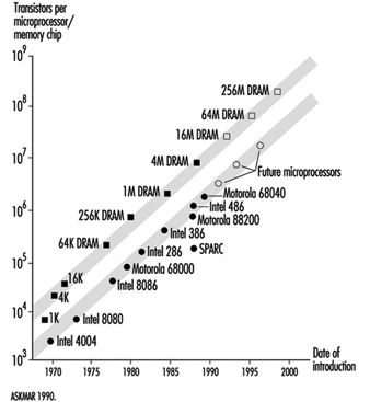
The economic importance of worldwide semiconductor sales is significant. Figure 2 is a projection by the Semiconductor Industry Association for worldwide and regional semiconductor sales for 1993 to 1998.
Figure 2. Worldwide semiconductor sales forecast
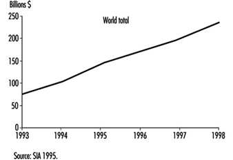
The semiconductor IC and computer/electronics assembly industries are unique compared to most other industrial categories in the relative composition of their production workforces. The semiconductor fabrication area has a high percentage of female operators that run the process equipment. The operator-related tasks typically do not require heavy lifting or excess physical strength. Also, many of the job tasks involve fine motor skills and attention to detail. Male workers predominate in the maintenance-related tasks, engineering functions and management. A similar composition is found in the computer/electronics assembly portion of this industry segment. Another unusual feature of this industry is the concentration of manufacturing in the Asia/Pacific area of the world. This is especially true in the final assembly or back-end processes in the semiconductor industry. This processing involves the positioning and placement of the fabricated integrated circuit chip (technically known as a die) on a chip carrier and lead frame. This processing requires precise positioning of the chip, typically through a microscope, and very fine motor skills. Again, female workers predominate this part of the process, with the majority of worldwide production being concentrated in the Pacific Rim, with high concentrations in Taiwan, Malaysia, Thailand, Indonesia and the Philippines, and growing numbers in China and Vietnam.
The semiconductor IC fabrication areas have various unusual properties and characteristics unique to this industry. Namely, the IC processing involves extremely tight particulate control regimens and requirements. A typical modern IC fabrication area may be rated as a Class 1 or less cleanroom. As a method of comparison, an outdoor environment would be greater than Class 500,000; a typical room in a house approximately Class 100,000; and a semiconductor back-end assembly area approximately Class 10,000. To attain this level of particulate control involves actually putting the fabrication worker in totally enclosed bunny suits that have air supply and filtration systems to control the levels of particulates generated by the workers in the fabrication area. The human occupants of the fabrication areas are considered very potent generators of fine particulates from their exhaled air, shedding of skin and hair, and from their clothing and shoes. This requirement for wearing confining clothing and isolating work routines has contributed to employees feeling like they are working in a “non-hospitable” work environment. See figure 3. Also, in the photolithographic area, the processing involves exposing the wafer to a photoactive solution, and then patterning an image on the wafer surface using ultraviolet light. To alleviate unwanted ultraviolet (UV) light from this processing area, special yellow lights are used (they lack the UV wavelength component normally found in indoor lighting). These yellow lights help to make the workers feel they are in a different work environment and can possibly have a disorienting affect on some individuals.
Figure 3. A state-of-the-art cleanroom
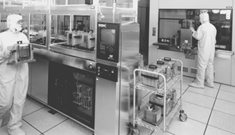
Environmental Issues in Metal Finishing and Industrial Coatings
Metal Finishing
The surface treatment of metals increases their durability and improves their appearance. A single product may undergo more than one surface treatment—for example, an auto body panel may be phosphated, primed and painted. This article deals with the processes used for surface treatment of metals and the methods used to reduce their environmental impact.
Operating a metal finishing business requires cooperation between company management, employees, government and the community to effectively minimize the environmental effect of the operations. Society is concerned with the amount and the long-term effects of pollution entering the air, water and land environment. Effective environmental management is established through detailed knowledge of all elements, chemicals, metals, processes and outputs.
Pollution prevention planning shifts the environmental management philosophy from reacting to problems to anticipating solutions focusing on chemical substitution, process change and internal recycling, using the following planning sequence:
- Initiate pollution prevention across all aspects of the business.
- Identify waste streams.
- Set priorities for action.
- Establish root cause of the waste.
- Identify and implement changes that reduce or eliminate the waste.
- Measure the results.
Continuous improvement is achieved by setting new priorities for action and repeating the sequence of actions.
Detailed process documentation will identify the waste streams and allow priorities to be set for waste reduction opportunities. Informed decisions about potential changes will encourage:
- easy and practical operational improvements
- process changes involving customers and suppliers
- changes to less harmful activities where possible
- reuse and recycling where change is not practical
- using landfilling of hazardous wastes only as a last resort.
Major processes and standard operating processes
Cleaning is required because all metal finishing processes require that parts to be finished be free from organic and inorganic soils, including oils, scale, buffing and polishing compounds. The three basic types of cleaners in use are solvents, vapour degreasers and alkaline detergents.
Solvents and vapour degreasing cleaning methods have been almost totally replaced by alkaline materials where the subsequent processes are wet. Solvents and vapour degreasers are still in use where parts must be clean and dry with no further wet processing. Solvents such as terpenes are in some instances replacing volatile solvents. Less toxic materials such as 1,1,1-trichloroethane have been substituted for more hazardous materials in vapour degreasing (although this solvent is being phased out as an ozone depleter).
Alkaline cleaning cycles usually include a soak immersion followed by an anodic electroclean, followed by a weak acid immersion. Non-etching, non-silicated cleaners are typically used to clean aluminium. The acids are typically sulphuric, hydrochloric and nitric.
Anodizing, an electrochemical process to thicken the oxide film on the metal surface (frequently applied to aluminium), treats the parts with dilute chromic or sulphuric acid solutions.
Conversion coating is used to provide a base for subsequent painting or to passivate for protection against oxidation. With chromating, parts are immersed in a hexavalent chrome solution with active organic and inorganic agents. For phosphating, parts are immersed in dilute phosphoric acid with other agents. Passivating is accomplished through immersion in nitric acid or nitric acid with sodium dichromate.
Electroless plating involves a deposition of metal without electricity. Copper or nickel electroless deposition is used in the manufacture of printed circuit boards.
Electroplating involves the deposition of a thin coat of metal (zinc, nickel, copper, chromium, cadmium, tin, brass, bronze, lead, tin-lead, gold, silver and other metals such as platinum) on a substrate (ferrous or non-ferrous). Process baths include metals in solution in acid, alkaline neutral and alkaline cyanide formulations (see figure 1).
Figure 1. Inputs and outputs for a typical electroplating line
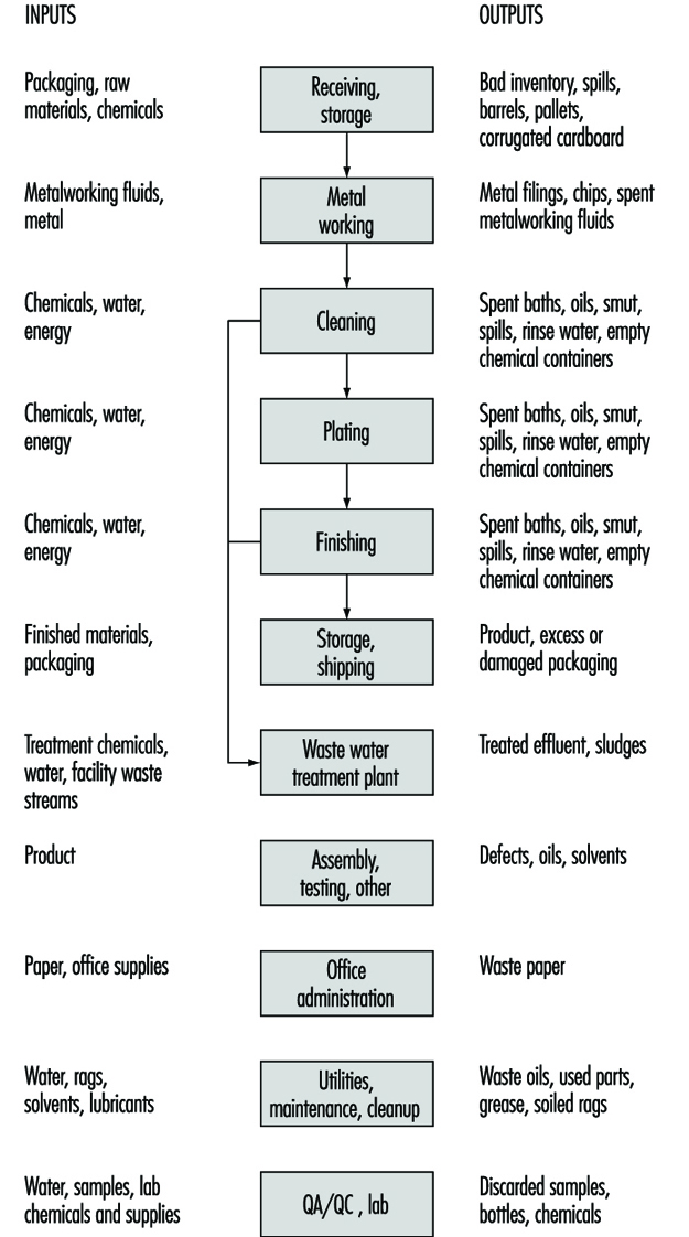
Chemical milling and etching are controlled dissolution immersion processes using chemical reagents and etchants. Aluminium is typically etched in caustic prior to anodizing or chemically brightened in a solution which could contain nitric, phosphoric and sulphuric acids.
Hot-dip coatings involve the application of metal to a workpiece by immersion in molten metal (zinc or tin galvanizing of steel).
Good management practices
Important safety, health and environmental improvements can be achieved through process improvements, such as:
- using counter-current rinsing and conductivity controls
- increasing drainage time
- using more or better wetting agents
- keeping process temperatures as high as possible to lower viscosity, thus increasing drag-out recovery (i.e., recovery of solution left on metal)
- using air agitation in rinsing to increase rinsing efficiency
- using plastic balls in plating tanks to reduce misting
- using improved filtration on plating tanks to reduce the frequency of purification treatment
- placing a curb around all process areas to contain spills
- using separate treatments for recoverable metals such as nickel
- installing recovery systems such as ion exchange, atmospheric evaporation, vacuum evaporation, electrolytic recovery, reverse osmosis and electrodialysis
- complementing drag-out recovery systems with reductions in drag-in of contaminants and improved cleaning systems
- using modern inventory controls to reduce waste and workplace hazards
- applying standard procedures (i.e., written procedures, regular operating reviews and sound operating logs) to provide the basis for a sound environmental management structure.
Environmental planning for specific wastes
Specific waste streams, usually spent plating solutions, can be reduced by:
- Filtration. Cartridge or diatomaceous earth filters can be used to remove the accumulation of solids, which reduce the efficiency of the process.
- Carbon treatment can be used to remove organic contaminants (most commonly applied in nickel plating, copper electroplating and zinc and cadmium plating).
- Purified water. The natural contaminants in water make-up and rinses (e.g., calcium, iron, magnesium, manganese, chlorine and carbonates) can be removed by using deionization, distillation or reverse osmosis. Improving rinse water efficiency reduces the volume of bath sludges requiring treatment.
- Cyanide bath carbonate freezing. Lowering the bath temperature to –3 °C crystallizes the carbonates formed in cyanide bath by the breakdown of cyanide, excessive anode current densities and the adsorption of carbon dioxide from the air and facilitates their removal.
- Precipitation. Removal of metal contaminants entering the bath as impurities in anodes can be achieved through precipitation with barium cyanide, barium hydroxide, calcium hydroxide, calcium sulphate or calcium cyanide.
- Hexavalent chrome alternatives. Hexavalent chromium can be replaced with trivalent chromium plating solutions for decorative plating. Chrome conversion coatings for paint pretreatments can sometimes be replaced by non-chrome conversion coatings or no-rinse chrome chemistries.
- Non-chelated process chemistries. Instead of chelators being added to process baths to control the concentration of free ions in the solution, non-chelated process chemistries can be used so that it may not be necessary to keep metals in solution. These metals can be allowed to precipitate and can be removed by continuous filtration.
- Non-cyanide process chemicals. Waste streams containing free cyanide are typically treated using hypochlorite or chlorine to accomplish oxidation, and complex cyanides are commonly precipitated using ferrous sulphate. Using non-cyanide process chemistries both eliminates a treatment step and reduces the sludge volume.
- Solvent degreasing. Hot alkaline cleaning baths can be used in place of solvent degreasing of workpieces before processing. The effectiveness of alkaline cleaners can be enhanced by applying electrocurrent or ultrasonics. The benefits of avoiding solvent vapours and sludges often outweigh any additional operating costs.
- Alkaline cleaners. Having to discard alkaline cleaners when the accumulation of oil, grease and soils from use reaches a level which impairs the cleaning efficiency of the bath can be avoided by using skimming devices to remove free-floating oils, settling devices or cartridge filters to remove particulates and oil-water coalescers and by using microfiltration or ultrafiltration to remove emulsified oils.
- Drag-out reduction. Reducing the volume of drag-out from process baths serves to reduce the amount of valuable process chemicals that contaminates the rinse water, which in turn reduces the amount of sludge that is generated by a conventional metal precipitation treatment process.
Several methods of reducing drag-out include:
- Process bath operating concentration. The chemical concentration should be kept as low as possible to minimize the viscosity (for quicker draining) and the quantity of chemicals (in the film).
- Process bath operating temperature. The viscosity of the process solution can be reduced by increasing the bath temperature.
- Wetting agents. The surface tension of the solution can be reduced by adding wetting agents to the process bath.
- Workpiece positioning. The workpiece should be positioned on the rack so that the adhering film drains freely and does not get trapped in grooves or cavities.
- Withdrawal or drainage time. The faster a workpiece is removed from the process bath, the thicker the film on the workpiece surface.
- Air knives. Blowing air at the workpiece as the workpiece rack is raised above the process tank can improve drainage and drying.
- Spray rinses. These can be used above heated baths so that the rinse flow rate equals the evaporation rate of the tank.
- Plating baths. Carbonates and organic contaminants should be removed to prevent accumulation of contamination that increases the viscosity of the plating bath.
- Drainage boards. The spaces between process tanks should be covered with drainage boards to capture process solutions and to return them to the process bath.
- Drag-out tanks. The workpieces should be placed in drag-out tanks (“static rinse” tanks) before the standard rinsing operation.
Drag-out recovery of chemicals uses a variety of technologies. These include:
- Evaporation. Atmospheric evaporators are most common, and vacuum evaporators offer energy savings.
- Ion exchange is used for chemical recovery of rinse water.
- Electrowinning. This is an electrolytic process whereby the dissolved metals in the solution are reduced and deposited on the cathode. The deposited metal is then recovered.
- Electrodialysis. This utilizes ion-permeable membranes and applied current in order to separate ionic species from the solution.
- Reverse osmosis. This utilizes a semi-permeable membrane to produce purified water and a concentrated ionic solution. High pressure is used to force the water through the membrane, while most dissolved salts are retained by the membrane.
Rinse water
Most of the hazardous waste produced in a metal finishing facility comes from waste water generated by the rinsing operations that follow cleaning and plating. By increasing rinse efficiency, a facility can significantly reduce waste water flow.
Two basic strategies improve rinsing efficiency. First, turbulence can be generated between the workpiece and the rinse water through spray rinses and rinse water agitation. Movement of the rack or forced water or air are used. Second, the contact time between the workpiece and the rinse water can be increased. Multiple rinse tanks set countercurrent in series will reduce the amount of rinse water used.
Industrial Coatings
The term coatings includes paints, varnishes, lacquers, enamels and shellacs, putties, wood fillers and sealers, paint and varnish removers, paint brush cleaners and allied paint products. Liquid coatings contain pigments and additives dispersed in a liquid binder and solvent mixture. Pigments are inorganic or organic compounds that provide coating colour and opacity and influence coating flow and durability. Pigments often contain heavy metals such as cadmium, lead, zinc, chromium and cobalt. The binder increases coating adhesiveness, cohesiveness and consistency and is the primary component that remains on the surface when coating is completed. Binders include a variety of oils, resins, rubbers and polymers. Additives such as fillers and extenders may be added to coatings to reduce manufacturing costs and increase coating durability.
The types of organic solvents used in coatings include aliphatic hydrocarbons, aromatic hydrocarbons, esters, ketones, glycol ethers and alcohols. Solvents disperse or dissolve the binders and decrease the coating viscosity and thickness. Solvents used in coatings formulations are hazardous because many are human carcinogens and are flammable or explosive. Most solvents contained in a coating evaporate when the coating cures, which generates volatile organic compound (VOC) emissions. VOC emissions are becoming increasingly regulated because of the negative effects on human health and the environment. Environmental concerns associated with conventional ingredients, coating application technologies and coating wastes are a driving force for developing pollution prevention alternatives.
Most coatings are used on architectural, industrial or special products. Architectural coatings are used in buildings and building products and for decorative and protective services such as varnishes to protect wood. Industrial facilities incorporate coating operations in various production processes. The automotive, metal can, farm machinery, coil coating, wood and metal furniture and fixtures, and household appliance industries are the major industrial coatings consumers.
Design of a coating formulation depends on the purpose of the coating application. Coatings provide aesthetics, and corrosion and surface protection. Cost, function, product safety, environmental safety, transfer efficiency and drying and curing speed determine formulations.
Coating processes
There are five operations comprising most coating processes: raw materials handling and preparation, surface preparation, coating, equipment cleaning and waste management.
Raw material handling and preparation
Raw material handling and preparation involves inventory storage, mixing operations, thinning and adjusting of coatings and raw material transfer through the facility. Monitoring and handling procedures and practices are needed to minimize the generation of wastes from spoilage, off specification and improper preparation that can result from excessive thinning and consequent wastage. Transfer, whether manual or through a piped system, must be scheduled to avoid spoilage.
Surface preparation
The type of surface preparation technique used depends on the surface being coated—previous preparation, amount of soil, grease, the coating to be applied and the surface finish required. Common preparation operations include degreasing, precoating or phosphating and coating removal. For metal finishing purposes, degreasing involves solvent wiping, cold cleaning or vapour degreasing with halogenated solvents, aqueous alkaline cleaning, semi-aqueous cleaning or aliphatic hydrocarbon cleaning to remove organic soil, dirt, oil and grease. Acid pickling, abrasive cleaning or flame cleaning are used to remove mill scale and rust.
The most common preparation operation for metal surfaces, other than cleaning, is phosphate coating, used to promote adhesion of organic coatings onto metal surfaces and retard corrosion. Phosphate coatings are applied by immersing or spraying metal surfaces with zinc, iron or manganese phosphate solution. Phosphating is a surface finishing process similar to electroplating, consisting of a series of process chemical and rinse baths in which parts are immersed to achieve the desired surface preparation. See the article “Surface treatment of metals” in this chapter.
Coating removal, chemical or mechanical, is conducted on surfaces that require recoating, repair or inspection. The most common chemical coating removal method is solvent stripping. These solutions usually contain phenol, methylene chloride and an organic acid to dissolve the coating from the coated surface. A final water wash to remove the chemicals can generate large quantities of wastewater. Abrasive blasting is the common mechanical process, a dry operation that uses compressed air to propel a blasting medium against the surface to remove the coating.
Surface preparation operations affect the quantity of waste from the specific preparation process. If the surface preparation is inadequate, resulting in poor coating, then removal of the coating and recoating adds to waste generation.
Coating
The coating operation involves transferring the coating to the surface and curing the coating on the surface. Most coating technologies fall into 1 of 5 basic categories: dip coating, roll coating, flow coating, spray coating, and the most common technique, air-atomized spray coating using solvent-based coatings.
Air-atomized spray coatings are usually conducted in a controlled environment because of solvent emissions and overspray. Overspray control devices are fabric filters or water walls, generating either used filters or wastewater from air scrubbing systems.
Curing is performed to convert the coating binder into a hard, tough, adherent surface. Curing mechanisms include: drying, baking or exposure to an electron beam or infrared or ultraviolet light. Curing generates significant VOCs from solvent-based coatings and poses a potential for explosion if the solvent concentrations rise above the lower explosive limit. Consequently, curing operations are equipped with air pollution control devices to prevent VOC emissions and for safety control to prevent explosions.
Environmental and health concerns, increased regulations affecting conventional coating formulations, high solvent costs and expensive hazardous waste disposal have created a demand for alternative coating formulations that contain less hazardous constituents and generate less waste when applied. Alternative coating formulations include:
- High-solid coatings, containing twice the amount of pigment and resin in the same volume of solvent as conventional coatings. Application lowers VOC emissions between 62 and 85% compared to conventional low-solid solvent-based coatings because the solvent content is reduced.
- Water-based coatings using water and an organic solvent mixture as the carrier with water used as the base. Compared to solvent-based coatings, water-based coatings generate between 80 and 95% less VOC emissions and spent solvents than conventional low-solid solvent-based coatings.
- Powder coatings containing no organic solvent, consisting of finely pulverized pigment and resin particles. They are either thermoplastic (high molecular weight resin for thick coatings) or thermosetting (low molecular weight compounds that form a thin layer before chemically cross-linking) powders.
Equipment cleaning
Equipment cleaning is a necessary, routine maintenance operation in coating processes. This creates significant amounts of hazardous waste, particularly if halogenated solvents are used for cleaning. Equipment cleaning for solvent-based coatings has traditionally been conducted manually with organic solvents to remove coatings from process equipment. Piping requires flushing with solvent in batches until clean. Coating equipment must be cleaned between product changes and after process shutdowns. The procedures and practices used will determine the level of waste generated from these activities.
Waste management
Several waste streams are generated by coating processes. Solid waste includes empty coating containers, coating sludge from overspray and equipment cleaning, spent filters and abrasive materials, dry coating and cleaning rags.
Liquid wastes include waste water from surface preparation, overspray control or equipment cleaning, off-specification or excess coating or surface preparation materials, overspray, spills and spent cleaning solutions. Onsite closed-loop recycling is becoming more popular for spent solvents as disposal costs rise. Water-based liquids are usually treated onsite prior to discharge to publicly owned treatment systems.
VOC emissions are generated by all conventional coating processes that use solvent-based coatings, requiring control devices such as carbon adsorption units, condensers or thermal catalytic oxidizers.
Metal Reclamation
Metal reclamation is the process by which metals are produced from scrap. These reclaimed metals are not distinguishable from the metals produced from primary processing of an ore of the metal. However, the process is slightly different and the exposure could be different. The engineering controls are basically the same. Metal reclamation is very important to the world economy because of the depletion of raw materials and the pollution of the environment created by scrap materials.
Aluminium, copper, lead and zinc comprise 95% of the production in the secondary non-ferrous metal industry. Magnesium, mercury, nickel, precious metals, cadmium, selenium, cobalt, tin and titanium are also reclaimed. (Iron and steel are discussed in the chapter Iron and steel industry. See also the article “Copper, lead and zinc smelting and refining” in this chapter.)
Control Strategies
Emission/exposure control principles
Metal reclamation involves exposures to dust, fumes, solvents, noise, heat, acid mists and other potential hazardous materials and risks. Some process and/or material handling modifications may be feasible to eliminate or reduce the generation of emissions: minimizing handling, lowering pot temperatures, decreasing dross formation and surface generation of dust, and modifying plant layout to reduce material handling or re-entrainment of settled dust.
Exposure can be reduced in some cases if machines are selected to perform high-exposure tasks so that employees may be removed from the area. This can also reduce ergonomic hazards due to materials handling.
To prevent cross contamination of clean areas in the plant, it is desirable to isolate processes generating significant emissions. A physical barrier will contain emissions and reduce their spread. Thus, fewer people are exposed, and the number of emission sources contributing to exposure in any one area will be reduced. This simplifies exposure evaluations and makes the identification and control of major sources easier. Reclaim operations are often isolated from other plant operations.
Occasionally, it is possible to enclose or isolate a specific emission source. Because enclosures are seldom air tight, a negative draught exhaust system is often applied to the enclosure. One of the most common ways to control emissions is to provide local exhaust ventilation at the point of emission generation. Capturing emissions at their source reduces the potential for emissions to disperse into the air. It also prevents secondary employee exposure created by the re-entrainment of settled contaminants.
The capture velocity of an exhaust hood must be great enough to prevent fumes or dust from escaping the air flow into the hood. The air flow should have enough velocity to carry fume and dust particles into the hood and to overcome the disrupting effects of cross drafts and other random air movements. The velocity required to accomplish this will vary from application to application. The use of recirculation heaters or personal cooling fans which can overcome local exhaust ventilation should be restricted.
All exhaust or dilution ventilation systems also require replacement air (known also as “make-up” air systems). If the replacement air system is well designed and integrated into natural and comfort ventilation systems, more effective control of exposures can be expected. For example, replacement air outlets should be placed so clean air flows from the outlet across the employees, towards the emission source and to the exhaust. This technique is often used with supplied-air islands and places the employee between clean incoming air and the emission source.
Clean areas are intended to be controlled through direct emission controls and housekeeping. These areas exhibit low ambient contaminant levels. Employees in contaminated areas can be protected by supplied-air service cabs, islands, stand-by pulpits and control rooms, supplemented by personal respiratory protection.
The average daily exposure of workers can be reduced by providing clean areas such as breakrooms and lunchrooms that are supplied with fresh filtered air. By spending time in a relatively contaminant-free area, the employees’ time-weighted average exposure to contaminants can be reduced. Another popular application of this principle is the supplied-air island, where fresh filtered air is supplied to the breathing zone of the employee at the workstation.
Sufficient space for hoods, duct work, control rooms, maintenance activities, cleaning and equipment storage should be provided.
Wheeled-vehicles are significant sources of secondary emissions. Where wheeled-vehicle transport is used, emissions can be reduced by paving all surfaces, keeping surfaces free of accumulated dusty materials, reducing vehicle travel distances and speed, and by re-directing vehicle exhaust and cooling fan discharge. Appropriate paving material such as concrete should be selected after considering factors such as load, use and care of surface. Coatings may be applied to some surfaces to facilitate wash down of roadways.
All exhaust, dilution and make-up air ventilation systems must be properly maintained in order to effectively control air contaminants. In addition to maintaining general ventilation systems, process equipment must be maintained to eliminate spillage of material and fugitive emissions.
Work practice programme implementation
Although standards emphasize engineering controls as a means of achieving compliance, work practice controls are essential to a successful control programme. Engineering controls can be defeated by poor work habits, inadequate maintenance and poor housekeeping or personal hygiene. Employees who operate the same equipment on different shifts can have significantly different airborne exposures because of differences in these factors between shifts.
Work practice programmes, although often neglected, represent good managerial practice as well as good common sense; they are cost effective but require a responsible and cooperative attitude on the part of employees and line supervisors. The attitude of senior management toward safety and health is reflected in the attitude of line supervisors. Likewise, if supervisors do not enforce these programmes, employees attitudes may suffer. Fostering good health and safety attitudes can be accomplished through:
- a cooperative atmosphere in which employees participate in the programmes
- formal training and educational programmes
- emphasizing the plant safety and health programme. Motivating employees and obtaining their trust is necessary in order to have an effective programme.
Work practice programmes cannot be simply “installed”. Just as with a ventilation system, they must be maintained and continually checked to insure that they are functioning properly. These programmes are the responsibility of management and employees. Programmes should be established to teach, encourage and supervise “good” (i.e., low exposure) practices.
Personal protective equipment
Safety glasses with side shields, coveralls, safety shoes and work gloves should be routinely worn for all jobs. Those engaged in casting and melting, or in casting alloys, should wear aprons and hand protection made of leather or other suitable materials to protect against the splatter of molten metal.
In operations where engineering controls are not adequate to control dust or fume emissions, appropriate respiratory protection should be worn. If noise levels are excessive, and cannot be engineered out or noise sources cannot be isolated, hearing protection should be worn. There should also be a hearing conservation programme, including audiometric testing and training.
Processes
Aluminium
The secondary aluminium industry utilizes aluminium-bearing scrap to produce metallic aluminium and aluminium alloys. The processes used in this industry include scrap pre-treatment, remelting, alloying and casting. The raw material used by the secondary aluminium industry includes new and old scrap, sweated pig and some primary aluminium. New scrap consists of clippings, forging and other solids purchased from the aircraft industry, fabricators and other manufacturing plants. Borings and turnings are by-product of the machining of castings, rods and forging by the aircraft and automobile industry. Drosses, skimmings and slags are obtained from primary reduction plants, secondary smelting plants and foundries. Old scrap includes automobile parts, household items and airplane parts. The steps involved are as follows:
- Inspection and sorting. Purchased aluminium scrap undergoes inspection. Clean scrap requiring no pre-treatment is transported to storage or is charged directly into the smelting furnace. The aluminium that needs pre-treatment is manually sorted. Free iron, stainless steel, zinc, brass and oversized materials are removed.
- Crushing and screening. Old scrap, especially casting and sheet contaminated with iron, are inputs to this process. Sorted scrap is conveyed to a crusher or hammer mill where the material is shredded and crushed, and the iron is torn away from the aluminium. The crushed material is passed over vibrating screens to remove dirt and fines.
- Baling. Specially designed baling equipment is used to compact bulky aluminium scrap such as scrap sheet, castings and clippings.
- Shredding/classifying. Pure aluminium cable with steel reinforcement or insulation is cut with alligator-type shears, then granulated or further reduced in hammer mills to separate the iron core and plastic coating from the aluminium.
- Burning/drying. Borings and turning are pre-treated in order to remove cutting oils, greases, moisture and free iron. The scrap is crushed in a hammer mill or ring crusher, the moisture and organics are volatilized in a gas- or oil-fired rotary dryer, the dried chips are screened to remove aluminium fines, the remaining material is magnetically treated for iron removal, and the clean, dried borings are sorted in tote boxes.
- Hot-dross processing. Aluminium can be removed from the hot dross discharged from the refining furnace by batch fluxing with a salt-cryolite mixture. This process is carried out in a mechanically rotated, refractory-lined barrel. The metal is tapped periodically through a hole in its base.
- Dry milling. In the dry-milling process, cold aluminium-laden dross and other residues are processed by milling, screening and concentrating to obtain a product containing a minimum aluminium content of 60 to 70%. Ball mills, rod mills or hammer mills can be used to reduce the oxides and non-metallics to fine powders. Separation of dirt and other non-recoverables from the metal is achieved by screening, air classification and/or magnetic separation.
- Roasting. Aluminium foil backed with paper, gutta-percha or insulation is an input in this process. In the roasting process, carboneous materials associated with aluminium foils are charged and then separated from the metal product.
- Aluminium sweating. Sweating is a pyrometallurgical process which is used to recover aluminium from high-iron-content scrap. High-iron aluminium scrap, castings and dross are inputs in this process. Open-flame reverberatory furnaces with sloping hearths are generally employed. Separation is accomplished as aluminium and other low-melting constituents melt and trickle down the hearth, through a grate and into air-cooled moulds, collecting pots or holding wells. The product is termed “sweated pig”. The higher-melting materials including iron, brass and oxidation products formed during the sweating process are periodically tapped from the furnace.
- Reverberatory (chlorine) smelting-refining. Reverberatory furnaces are used to convert clean sorted scrap, sweated pigs or, in some cases, untreated scrap into specification alloys. The scrap is charged to the furnace by mechanical means. Materials are added for processing by batch or continuous feed. After the scrap is charged a flux is added to prevent contact with and subsequent oxidation of the melt by air (cover flux). Solvent fluxes are added which react with non-metallics, such as residues from burned coatings and dirt, to form insolubles which float to the surface as slag. Alloying agents are then added, depending on the specifications. Demagging is the process which reduces the magnesium content of the molten charge. When demagging with chlorine gas, chlorine is injected through carbon tubes or lances and reacts with magnesium and aluminium as it bubbles. In the skimming step impure semi-solid fluxes are skimmed off the surface of the melt.
- Reverberatory (fluorine) smelting-refining. This process is similar to the reverberatory (chlorine) smelting-refining process except that aluminium fluoride rather than chlorine is employed.
Table 1 lists exposure and controls for aluminium reclamation operations.
Table 1. Engineering/administrative controls for aluminium, by operation
|
Process equipment |
Exposure |
Engineering/administrative controls |
|
Sorting |
Torch desoldering—metal fumes such as lead and cadmium |
Local exhaust ventilation during desoldering; PPE—respiratory protection when desoldering |
|
Crushing/screening |
Non-specific dusts and aerosol, oil mists, metal particulates, and noise |
Local exhaust ventilation and general area ventilation, isolation of noise source; PPE—hearing protection |
|
Baling |
No known exposure |
No controls |
|
Burning/drying |
Non-specific particulate matter which may include metals, soot, and condensed heavy organics. Gases and vapours containing fluorides, sulphur dioxide, chlorides, carbon monoxide, hydrocarbons and aldehydes |
Local exhaust ventilation, general area ventilation, heat stress work/rest regimen, fluids, isolation of noise source; PPE—hearing protection |
|
Hot-dross processing |
Some fumes |
Local exhaust ventilation, general area ventilation |
|
Dry milling |
Dust |
Local exhaust ventilation, general area ventilation |
|
Roasting |
Dust |
Local exhaust ventilation, general area ventilation, heat stress work/rest regimen, fluids, isolation of noise source; PPE—hearing protection |
|
Sweating |
Metal fumes and particulates, non-specific gases and vapours, heat and noise |
Local exhaust ventilation, general area ventilation, heat stress work/rest regimen, fluids, isolation of noise source; PPE—hearing protection and respiratory protection |
|
Reverberatory (chlorine) smelting-refining |
Products of combustion, chlorine, hydrogen chlorides, metal chlorides, aluminium chlorides, heat and noise |
Local exhaust ventilation, general area ventilation, heat stress work/rest regimen, fluids, isolation of noise source; PPE—hearing protection and respiratory protection |
|
Reverberatory (fluorine) smelting-refining |
Products of combustion, fluorine, hydrogen flluorides, metal fluorides, aluminium fluorides, heat and noise |
Local exhaust ventilation, general area ventilation, heat stress work/rest regimen, fluids, isolation of noise source; PPE—hearing protection and respiratory protection |
Copper reclamation
The secondary copper industry utilizes copper-bearing scrap to produce metallic copper and copper based alloys. The raw materials used can be classified as new scrap produced in the fabrication of finished products or old scrap from obsolete worn out or salvaged articles. Old scrap sources include wire, plumbing fixtures, electrical equipment, automobiles and domestic appliances. Other materials with copper value include slags, drosses, foundry ashes and sweepings from smelters. The following steps are involved:
- Stripping and sorting. Scrap is sorted on the bases of its copper content and cleanliness. Clean scrap may be manually separated for charging directly to a melting and alloying furnace. Ferrous components can be separated magnetically. Insulation and lead cable coverings are stripped by hand or by specially designed equipment.
- Briquetting and crushing. Clean wire, thin plate, wire screen, borings, turnings and chips are compacted for easier handling. The equipment used includes hydraulic baling presses, hammer mills and ball mills.
- Shredding. The separation of copper wire from insulation is accomplished by reducing the size of the mixture. The shredded material is then sorted by air or hydraulic classification with magnetic separation of any ferrous materials.
- Grinding and gravity separation. This process accomplishes the same function as shredding but uses an aqueous separation medium and different input materials such as slags, drosses, skimmings, foundry ashes, sweepings and baghouse dust.
- Drying. Borings, turnings and chips containing volatile organic impurities such as cutting fluids, oils and greases are removed.
- Insulation burning. This process separates insulation and other coatings from copper wire by burning these materials in furnaces. The wire scrap is charged in batches to a primary ignition chamber or afterburner. Volatile combustion products are then passed through a secondary combustion chamber or baghouse for collection. Non-specific particulate matter is generated which may include smoke, clay and metal oxides. Gases and vapours may contain oxides of nitrogen, sulphur dioxide, chlorides, carbon monoxide, hydrocarbons and aldehydes.
- Sweating. The removal of low vapour-melting components from scrap is accomplished by heating the scrap to a controlled temperature which is just above the melting point of the metals to be sweated out. The primary metal, copper, is generally not the melted component.
- Ammonium carbonate leaching. Copper can be recovered from relatively clean scrap by leaching and dissolution in a basic ammonium carbonate solution. Cupric ions in an ammonia solution will react with metallic copper to produce cuprous ions, which can be reoxidized to the cupric state by air oxidation. After the crude solution is separated from the leach residue, the copper oxide is recovered by steam distillation.
- Steam distillation. Boiling the leached material from the carbonate leaching process precipitates the copper oxide. The copper oxide is then dried.
- Hydrothermal hydrogen reduction. Ammonium carbonate solution containing copper ions is heated under pressure in hydrogen, precipitating the copper as a powder. The copper is filtered, washed, dried and sintered under a hydrogen atmosphere. The powder is ground and screened.
- Sulphuric acid leaching. Scrap copper is dissolved in hot sulphuric acid to form a copper sulphate solution for feed to the electrowinning process. After digestion, the undissolved residue is filtered off.
- Converter smelting. Molten black copper is charged to converter, which is a pear-shaped or cylindrical steel shell lined refractory brick. Air is blown into the molten charges through nozzles called tuyères. The air oxidizes copper sulphide and other metals. A flux containing silica is added to react with the iron oxides to form an iron silicate slag. This slag is skimmed from the furnace, usually by tipping the furnace and then there is a secondary blow and skim. The copper from this process is called blister copper. The blister copper is generally further refined in a fire refining furnace.
- Fire refining. The blister copper from the converter is fire refined in a cylindrical tilting furnace, a vessel like a reverberatory furnace. The blister copper is charged to the refining vessel in an oxidizing atmosphere. The impurities are skimmed from the surface and a reducing atmosphere is created by the addition of green logs or natural gas. The resulting molten metal is then cast. If the copper is to be electrolytically refined, the refined copper will be cast as an anode.
- Electrolytic refining. The anodes from the fire refining process are placed in a tank containing sulphuric acid and a direct current. The copper from the anode is ionized and the copper ions are deposited on a pure copper starter sheet. As the anodes dissolve in the electrolyte the impurities settle to the bottom of the cell as a slime. This slime can be additionally processed to recover other metal values. The cathode copper produced is melted and cast into a variety of shapes.
Table 2 lists exposures and controls for copper reclamation operations.
Table 2. Engineering/administrative controls for copper, by operation
|
Process equipment |
Exposures |
Engineering/administrative controls |
|
Stripping and sorting |
Air contaminants from material handling and desoldering or scrap cutting |
Local exhaust ventilation, general area ventilation |
|
Briquetting and crushing |
Non-specific dusts and aerosol, oil mists, metal particulates and noise |
Local exhaust ventilation and general area ventilation, isolation of noise source; PPE—hearing protection and respiratory protection |
|
Shredding |
Non-specific dusts, wire insulation material, metal particulates and noise |
Local exhaust ventilation and general area ventilation, isolation of noise source; PPE—hearing protection and respiratory protection |
|
Grinding and gravity separation |
Non-specific dusts, metal particulates from fluxes, slags and drosses, and noise |
Local exhaust ventilation and general area ventilation, isolation of noise source; PPE—hearing protection and respiratory protection |
|
Drying |
Non-specific particulate matter, which may include metals, soot and condensed heavy organics |
Local exhaust ventilation, general area ventilation, work/rest regimen, fluids, isolation of noise source; PPE—hearing protection and respiratory protection |
|
Insulation burning |
Non-specific particulate matter which may include smoke, clay |
Local exhaust ventilation, general area ventilation, work/rest regimen, fluids, isolation of noise source; PPE—respiratory protection |
|
Sweating |
Metal fumes and particulates, non-specific gases, vapours and particulates |
Local exhaust ventilation, general area ventilation, work/rest regimen, fluids, isolation of noise source; PPE—hearing protection and respiratory protection |
|
Ammonium carbonate leaching |
Ammonia |
Local exhaust ventilation, general area ventilation; PPE—respiratory protection |
|
Steam distillation |
Ammonia |
Local exhaust ventilation, general area ventilation; PPE—glasses with side shields |
|
Hydrothermal hydrogen reduction |
Ammonia |
Local exhaust ventilation, general area ventilation; PPE—respiratory protection |
|
Sulphuric acid leaching |
Sulphuric acid mists |
Local exhaust ventilation, general area ventilation |
|
Converter smelting |
Volatile metals, noise |
Local exhaust ventilation, general area ventilation; PPE—respiratory protection and hearing protection |
|
Electric crucible smelting |
Particulate, sulphur and nitrogen oxides, soot, carbon monoxide, noise |
Local exhaust ventilation, general area ventilation; PPE—hearing protection |
|
Fire refining |
Sulphur oxides, hydrocarbons, particulates |
Local exhaust ventilation, general area ventilation; PPE—hearing protection |
|
Electrolytic refining |
Sulphuric acid and metals from sludge |
Local exhaust ventilation, general area ventilation |
Lead reclamation
Raw materials purchased by secondary lead smelters may require processing prior to being charged into a smelting furnace. This section discusses the most common raw materials which are purchased by secondary lead smelters and feasible engineering controls and work practices to limit employee exposure to lead from raw materials processing operations. It should be noted that lead dust can generally be found throughout lead reclamation facilities and that any vehicular air is likely to stir up lead dust which can then be inhaled or adhere to shoes, clothing, skin and hair.
Automotive batteries
The most common raw material at a secondary lead smelter is junk automotive batteries. Approximately 50% of the weight of a junk automotive battery will be reclaimed as metallic lead in the smelting and refining process. Approximately 90% of the automotive batteries manufactured today utilize a polypropylene box or case. The polypropylene cases are reclaimed by almost all secondary lead smelters due to the high economic value of this material. Most of these processes can generate metal fumes, in particular lead and antimony.
In automotive battery breaking there is a potential for forming arsine or stibine due to the presence of arsenic or antimony used as hardening agents in grid metal and the potential for having nascent hydrogen present.
The four most common processes for breaking automotive batteries are:
- high speed saw
- slow speed saw
- shear
- whole battery crushing (Saturn crusher or shredder or hammer mill).
The first three of these processes involve cutting the top off of the battery, then dumping the groups, or lead-bearing material. The fourth process involves crushing the entire battery in a hammer mill and separating the components by gravity separation.
Automotive battery separation takes place after automotive batteries have been broken in order that the lead-bearing material can be separated from the case material. Removing the case may generate acid mists. The most widely used techniques for accomplishing this task are:
- The manual technique. This is used by the vast majority of secondary lead smelters and remains the most widely used technique in small to mid-sized smelters. After the battery passes through the saw or shear, an employee manually dumps the groups or lead-bearing material into a pile and places the case and top of the battery into another pile or conveyance system.
- A tumbler device. Batteries are placed into a tumbler device after the tops have been sawed/sheared off to separate the groups from the cases. Ribs inside the tumbler dump the groups as it slowly rotates. Groups fall through the slots in the tumbler while the cases are conveyed to the far end and are collected as they exit. Plastic and rubber battery cases and tops are further processed after being separated from the lead bearing material.
- A sink/float process. The sink/float process typically is combined with the hammer mill or crushing process for battery breaking. Battery pieces, both lead bearing and cases, are placed in a series of tanks filled with water. Lead bearing material sinks to the bottom of the tanks and is removed by screw conveyor or drag chain while the case material floats and is skimmed off the tank surface.
Industrial batteries which were used to power mobile electric equipment or for other industrial uses are purchased periodically for raw material by most secondary smelters. Many of these batteries have steel cases which require removal by cutting the case open with a cutting torch or a hand-held gas powered saw.
Other purchased lead-bearing scrap
Secondary lead smelters purchase a variety of other scrap materials as raw materials for the smelting process. These materials include battery manufacturing plant scrap, drosses from lead refining, scrap metallic lead such as linotype and cable covering, and tetraethyl lead residues. These types of materials may be charged directly into smelting furnaces or mixed with other charge materials.
Raw material handling and transport
An essential part of the secondary lead smelting process is the handling, transportation and storage of raw material. Materials are transported by fork-lifts, front-end loaders or mechanical conveyors (screw, bucket elevator or belt). The primary method of material transporting in the secondary lead industry is mobile equipment.
Some common mechanical conveyance methods which are used by secondary lead smelters include: belt conveying systems that can be used to transport furnace feed material from storage areas to the furnace charring area; screw conveyors for transporting flue dust from the baghouse to an agglomeration furnace or a storage area or bucket elevators and drag chains/lines.
Smelting
The smelting operation at a secondary lead smelter involves the reduction of lead-bearing scrap into metallic lead in a blast furnace or reverberatory.
Blast furnaces are charged with lead-bearing material, coke (fuel) limestone and iron (flux). These materials are fed into the furnace at the top of the furnace shaft or through a charge door in the side of the shaft neat the top of the furnace. Some environmental hazards associated with blast furnace operations are metal fumes and particulates (especially lead and antimony), heat, noise and carbon monoxide. A variety of charge material conveying mechanisms are used in the secondary lead industry. The skip hoist is probably the most common. Other devices in use include vibratory hoppers, belt conveyors and bucket elevators.
Blast furnace tapping operations involve removing the molten lead and slag from the furnace into moulds or ladles. Some smelters tap metal directly into a holding kettle which keeps the metal molten for refining. The remaining smelters cast the furnace metal into blocks and allow the blocks to solidify.
Blast air for the combustion process enters the blast furnace through tuyères which occasionally begin to fill with accretions and must be physically punched, usually with a steel rod, to keep them from being obstructed. The conventional method to accomplish this task is to remove the cover of the tuyères and insert the steel rod. After the accretions have been punched, the cover is replaced.
Reverberatory furnaces are charged with lead-bearing raw material by a furnace charging mechanism. Reverberatory furnaces in the secondary lead industry typically have a sprung arch or hanging arch constructed of refractory brick. Many of the contaminants and physical hazards associated with reverberatory furnaces are similar to those of blast furnaces. Such mechanisms can be a hydraulic ram, a screw conveyor or other devices similar to those described for blast furnaces.
Reverberatory furnace tapping operations are very similar to blast-furnace tapping operations.
Refining
Lead refining in secondary lead smelters is conducted in indirect fired kettles or pots. Metal from the smelting furnaces is typically melted in the kettle, then the content of trace elements is adjusted to produce the desired alloy. Common products are soft (pure) lead and various alloys of hard (antimony) lead.
Virtually all secondary lead refining operations employ manual methods for adding alloying materials to the kettles and employ manual drossing methods. Dross is swept to the rim of the kettle and removed by shovel or large spoon into a container.
Table 3 lists exposures and controls for lead reclamation operations.
Table 3. Engineering/administrative controls for lead, by operation
|
Process equipment |
Exposures |
Engineering/administrative controls |
|
Vehicles |
Lead dust from roads and splashing water containing lead |
Water washdown and keeping areas wetted down. Operator training, prudent work practices and good housekeeping are key elements in minimizing lead emissions when operating mobile equipment. Enclose equipment and provide a positive pressure filtered air system. |
|
Conveyors |
Lead dust |
It is also preferable to equip belt conveyor systems with self-cleaning tail pulleys or belt wipes if they are used to transport furnace feed materials or flue dusts. |
|
Battery decasing |
Lead dust, acid mists |
Local exhaust ventilation, general area ventilation |
|
Charge preparation |
Lead dust |
Local exhaust ventilation, general area ventilation |
|
Blast furnace |
Metal fumes and particulates (lead, antimony), heat and noise, carbon monoxide |
Local exhaust ventilation, general area ventilation, work/rest regimen, fluids, isolation of noise source; PPE—respiratory protection and hearing protection |
|
Reverberatory furnace |
Metal fumes and particulates (lead, antimony), heat and noise |
Local exhaust ventilation, general area ventilation, work/rest regimen, fluids, isolation of noise source; PPE—respiratory protection and hearing protection |
|
Refining |
Lead particulates and possibly alloying metals and fluxing agents, noise |
Local exhaust ventilation, general area ventilation; PPE—hearing protection |
|
Casting |
Lead particulates and possibly alloying metals |
Local exhaust ventilation, general area ventilation |
Zinc reclamation
The secondary zinc industry utilizes new clippings, skimmings and ashes, die-cast skimmings, galvanizers’ dross, flue dust and chemical residue as sources of zinc. Most of the new scrap processed is zinc- and copper-based alloys from galvanizing and die-casting pots. Included in the old scrap category are old zinc engravers’ plates, die castings, and rod and die scrap. The processes are as follows:
- Reverberatory sweating. Sweating furnaces are used to separate zinc from other metals by controlling the furnace temperature. Scrap die-cast products, such as automobile grilles and licence plate frames, and zinc skins or residues are starting materials for the process. The scrap is charged to the furnace, flux is added and the contents melted. The high-melting residue is removed and the molten zinc flows out of the furnace directly to subsequent processes, such as melting, refining or alloying, or to collecting vessels. Metal contaminants include zinc, aluminium, copper, iron, lead, cadmium, manganese and chromium. Other contaminants are fluxing agents, sulphur oxides, chlorides and fluorides.
- Rotary sweating. In this process zinc scrap, die-cast products, residues and skimmings are charged to a direct-fired furnace and melted. The melt is skimmed, and zinc metal is collected in kettles situated outside the furnace. Unmeltable material, the slag, is then removed prior to recharging. The metal from this process is sent to distillation or alloying process. Contaminants are similar to those of reverberatory sweating.
- Muffle sweating and kettle (pot) sweating. In these processes zinc scrap, die-vapour-cast products, residues and skimmings are charged to the muffle furnace, the material sweated and the sweated zinc is sent to refining or alloying processes. The residue is removed by a shaker screen which separates the dross from the slag. Contaminants are similar to those of reverberatory sweating.
- Crushing/screening. Zinc residues are pulverized or crushed to break down physical bonds between metallic zinc and contaminant fluxes. The reduced material is then separated in a screening or pneumatic classification step. Crushing can produce zinc oxide and minor amounts of heavy metals and chlorides.
- Sodium carbonate leaching. Residues are chemically treated to leach out and convert zinc to zinc oxide. The scrap is first crushed and washed. In this step, the zinc is leached out of the material. The aqueous portion is treated with sodium carbonate, causing zinc to precipitate. The precipitate is dried and calcined to yield crude zinc oxide. The zinc oxide is then reduced to zinc metal. Various zinc salt contaminants can be produced.
- Kettle (pot), crucible, reverberatory, electric induction melting. The scrap is charged to the furnace and fluxes are added. The bath is agitated to form a dross that can be skimmed from the surface. After the furnace has been skimmed the zinc metal is poured into ladles or moulds. Zinc oxide fumes, ammonia and ammonium chloride, hydrogen chloride and zinc chloride can be produced.
- Alloying. The function of this process is to produce zinc alloys from pre-treated scrap zinc metal by adding to it in a refining kettle fluxes and alloying agents either in the solidified or molten form. The contents are then mixed, the dross skimmed, and the metal is cast into various shapes. Particulates containing zinc, alloying metals, chlorides, non-specific gases and vapours, as well as heat, are potential exposures.
- Muffle distillation. The muffle distillation process is used to reclaim zinc from alloys and to manufacture pure zinc ingots. The process is semi-continuous which involves charging molten zinc from a melting pot or sweating furnace to the muffle section and vaporizing the zinc and condensing the vaporized zinc and tapping from the condenser to moulds. The residue is removed periodically from the muffle.
- Retort distillation/oxidation and muffle distillation/oxidation. The product of the retort distillation/oxidation and muffle distillation/oxidation processes is zinc oxide. The process is similar to retort distillation through the vaporization step, but, in this process, the condenser is bypassed and combustion air is added. The vapour is discharged through an orifice into an air stream. Spontaneous combustion occurs inside a refractory vapour-lined chamber. The product is carried by the combustion gases and excess air into a baghouse where the product is collected. Excess air is present to insure complete oxidation and to cool the product. Each of these distillation processes can lead to zinc oxide fume exposures, as well as other metal particulate and oxides of sulphur exposure.
Table 4 lists exposures and controls for zinc reclamation operations.
Table 4. Engineering/administrative controls for zinc, by operation
|
Process equipment |
Exposures |
Engineering/administrative controls |
|
Reverberatory sweating |
Particulates containing zinc, aluminium, copper, iron, lead, cadmium, manganese and chromium, contaminants from fluxing agents, sulphur oxides, chlorides and fluorides |
Local exhaust ventilation, general area ventilation, heat stress–work/rest regimen, fluids |
|
Rotary sweating |
Particulates containing zinc, aluminium, copper, iron, lead, cadmium, manganese and chromium, contaminants from fluxing agents, sulphur oxides, chlorides and fluorides |
Local exhaust ventilation, general area ventilation, work/rest regimen, fluids |
|
Muffle sweating and kettle (pot) sweating |
Particulates containing zinc, aluminium, copper, iron, lead, cadmium, manganese and chromium, contaminants from fluxing agents, sulphur oxides, chlorides and fluorides |
Local exhaust ventilation, general area ventilation, work/rest regimen, fluids |
|
Crushing/screening |
Zinc oxide, minor amounts of heavy metals, chlorides |
Local exhaust ventilation, general area ventilation |
|
Sodium carbonate leaching |
Zinc oxide, sodium carbonate, zinc carbonate, zinc hydroxide, hydrogen chloride, zinc chloride |
Local exhaust ventilation, general area ventilation |
|
Kettle (pot) melting crucible, reverberatory, electric induction melting |
Zinc oxide fumes, ammonia, ammonia chloride, hydrogen chloride, zinc chloride |
Local exhaust ventilation, general area ventilation, work/rest regimen, fluids |
|
Alloying |
Particulates containing zinc, alloying metals, chlorides; non-specific gases and vapours; heat |
Local exhaust ventilation, general area ventilation, work/rest regimen, fluids |
|
Retort distillation, retort distillation/oxidation and muffle distillation |
Zinc oxide fumes, other metal particulates, oxides of sulphur |
Local exhaust ventilation, general area ventilation, work/rest regimen, fluids |
|
Graphite rod resistor distillation |
Zinc oxide fumes, other metal particulates, oxides of sulphur |
Local exhaust ventilation, general area ventilation, work/rest regimen, fluids |
Magnesium reclamation
Old scrap is obtained from sources such as scrap automobile and aircraft parts and old and obsolete lithographic plates, as well as some sludges from primary magnesium smelters. New scrap consists of clippings, turnings, borings, skimmings, slags, drosses and defective articles from sheet mills and fabrication plants. The greatest danger in handling magnesium is that of fire. Small fragments of the metal can readily be ignited by a spark or flame.
- Hand sorting. This process is used to separate magnesium and magnesium-alloy fractions from other metals present in the scrap. The scrap is spread out manually, sorted on the basis of weight.
- Open pot melting. This process is used to separate magnesium from contaminants in the sorted scrap. Scrap is added to a crucible, heated and a flux consisting of a mixture of calcium, sodium and potassium chlorides is added. The molten magnesium is then cast into ingots.
Table 5 lists exposures and controls for magnesium reclamation operations.
Table 5. Engineering/administrative controls for magnesium, by operation
|
Process equipment |
Exposures |
Engineering/administrative |
|
Scrap sorting |
Dust |
Water washdown |
|
Open pot melting |
Fumes and dust, a high potential for fires |
Local exhaust ventilation and general area ventilation and work practices |
|
Casting |
Dust and fumes, heat and a high potential for fires |
Local exhaust ventilation, general area ventilation, work/rest regimen, fluids |
Mercury reclamation
The major sources for mercury are dental amalgams, scrap mercury batteries, sludges from electrolytic processes that use mercury as a catalyst, mercury from dismantled chlor-alkali plants and mercury-containing instruments. Mercury vapour can contaminate each of these processes.
- Crushing. The crushing process is used to release residual mercury from metal, plastic and glass containers. After the containers are crushed, the contaminated liquid mercury is sent to the filtering process.
- Filtration. Insoluble impurities such as dirt are removed by passing the mercury-vapour bearing scrap through a filter media. The filtered mercury is fed to the oxygenation process and the solids which do not pass through the filters are sent to retort distillation.
- Vacuum distillation. Vacuum distillation is employed to refine contaminated mercury when the vapour pressures of the impurities are substantially lower than that of mercury. Mercury charge is vaporized in a heating pot and the vapours are condensed using a water-cooled condenser. Purified mercury is collected and sent to the bottling operation. The residue remaining in the heating pot is sent to the retorting process to recover the trace amounts of mercury that were not recovered in the vacuum distillation process.
- Solution purification. This process removes metallic and organic contaminants by washing the raw liquid mercury with a dilute acid. The steps involved are: leaching the raw liquid mercury with dilute nitric acid to separate metallic impurities; agitating the acid-mercury with compressed air to provide good mixing; decanting to separate the mercury from the acid; washing with water to remove the residual acid; and filtering the mercury in a medium such as activated carbon or silica gel to remove the last traces of moisture. In addition to mercury vapour there can be exposure to solvents, organic chemicals and acid mists.
- Oxygenation. This process refines the filtered mercury by removing metallic impurities by oxidation with sparging air. The oxidation process involves two steps, sparging and filtering. In the sparging step, contaminated mercury is agitated with air in a closed vessel to oxidize the metallic contaminants. After sparging, the mercury is filtered in a charcoal bed to remove the solid metal oxides.
- Retorting. The retorting process is used to produce pure mercury by volatilizing the mercury found in solid mercury-bearing scrap. The steps involved in retorting are: heating the scrap with an external heat source in a closed still pot or stack of trays to vaporize the mercury; condensing the mercury vapour in water-cooled condensers; collecting the condensed mercury in a collecting vessel.
Table 6 lists exposures and controls for mercury reclamation operations.
Table 6. Engineering/administrative controls for mercury, by operation
|
Process equipment |
Exposures |
Engineering/administrative controls |
|
Crushing |
Volatile mercury |
Local exhaust; PPE—respiratory protection |
|
Filtration |
Volatile mercury |
Local exhaust ventilation; PPE—respiratory protection |
|
Vacuum distillation |
Volatile mercury |
Local exhaust ventilation; PPE—respiratory protection |
|
Solution purification |
Volatile mercury, solvents, organics and acid mists |
Local exhaust ventilation, general area ventilation; PPE—respiratory protection |
|
Oxidation |
Volatile mercury |
Local exhaust ventilation; PPE—respiratory protection |
|
Retorting |
Volatile mercury |
Local exhaust ventilation; PPE—respiratory protection |
Nickel reclamation
The principal raw materials for nickel reclamation are nickel-, copper- and aluminium-vapour based alloys, which can be found as old or new scrap. Old scrap comprises alloys that are salvaged from machinery and airplane parts, while new scrap refers to sheet scrap, turnings and solids which are by-products of the manufacture of alloy products. The following steps are involved in nickel reclamation:
- Sorting. The scrap is inspected and manually separated from the non-metallic and non-nickel materials. Sorting produces dust exposures.
- Degreasing. Nickel scrap is degreased by using trichloroethylene. The mixture is filtrated or centrifuged to separate the nickel scrap. The spent solvent solution of trichloroethylene and grease goes through a solvent recovery system. There can be solvent exposure during degreasing.
- Smelting (electric arc or rotary reverberatory) furnace. Scrap is charged to an electric arc furnace and a reducing agent added, usually lime. The charge is melted and is either cast into ingots or sent directly to a reactor for additional refining. Fumes, dust, noise and heat exposures are possible.
- Reactor refining. The molten metal is introduced into a reactor where cold-base scrap and pig nickel are added, followed by lime and silica. Alloying materials such as manganese, columbium or titanium are then added to produce the desired alloy composition. Fumes, dust, noise and heat exposures are possible.
- Ingot casting. This process involves casting the molten metal from the smelting furnace or the refining reactor into ingots. The metal is poured into moulds and allowed to cool. The ingots are removed from the moulds. Heat and metal fume exposures are possible.
Exposures and control measures for nickel reclamation operations are listed in table 7.
Table 7. Engineering/administrative controls for nickel, by operation
|
Process equipment |
Exposures |
Engineering/administrative controls |
|
Sorting |
Dust |
Local exhaust and solvent substitution |
|
Degreasing |
Solvent |
Local exhaust ventilation and solvent substitution and/or recovery, general area ventilation |
|
Smelting |
Fumes, dust, noise, heat |
Local exhaust ventilation, work/rest regimen, fluids; PPE—respiratory protection and hearing protection |
|
Refining |
Fumes, dust, heat, noise |
Local exhaust ventilation, general area ventilation, work/rest regimen, fluids; PPE—respiratory protection and hearing protection |
|
Casting |
Heat, metal fumes |
Local exhaust ventilation, general area ventilation, work/rest regimen, fluids |
Precious metals reclamation
The raw materials for the precious metal industry consist of both old and new scrap. Old scrap includes electronic components from obsolete military and civilian equipment and scrap from the dental industry. New scrap is generated during the fabrication and manufacturing of precious metal products. The products are the elemental metals such as gold, silver, platinum and palladium. Precious metal processing includes the following steps:
- Hand sorting and shredding. Precious metal-bearing scrap is hand sorted and crushed and shredded in a hammer mill. Hammer mills are noisy.
- Incineration process. Sorted scrap is incinerated to remove paper, plastic and organic liquid contaminants. Organic chemicals, combustion gases and dust exposures are possible.
- Blast-furnace smelting. Treated scrap is charged to a blast furnace, along with coke, flux and recycled slag metal oxides. The charge is melted and slagged, producing black copper which contains the precious metals. The hard slag that is formed contains most of the slag impurities. Dust and noise may be present.
- Converter smelting. This process is designed to further purify the black copper by blowing air through the melt in a converter. Slag-containing metal contaminants are removed and recycled to the blast furnace. The copper bullion containing the precious metals is cast into moulds.
- Electrolytic refining. Copper bullion serves as the anode of an electrolytic cell. Pure copper thus plates out on the cathode while the precious metals fall to the bottom of the cell and are collected as slimes. The electrolyte used is copper sulphate. Acid mist exposures are possible.
- Chemical refining. The precious metal slime from the electrolytic refining process is chemically treated to recover the individual metals. Cyanide-based processes are used to recover gold and silver, which can also be recovered by dissolving them in aqua regia solution and/or nitric acid, followed by precipitation with ferrous sulphate or sodium chloride to recover the gold and silver, respectively. The platinum-group metals can be recovered by dissolving them in molten lead, which is then treated with nitric acid and leaves a residue from which the platinum-group metals can be selectively precipitated. The precious metal precipitates are then either melted or ignited in order to collect the gold and silver as grains and the platinum metals as sponge. There can be acid exposures.
Exposures and controls are listed, by operation, in table 8 (see also “Gold smelting and refining”).
Table 8. Engineering/administrative controls for precious metals, by operation
|
Process equipment |
Exposures |
Engineering/administrative controls |
|
Sorting and shredding |
Hammermill is a potential noise hazard |
Noise control material; PPE—hearing protection |
|
Incineration |
Organics, combustion gases and dust |
Local exhaust ventilation and general area ventilation |
|
Blast furnace smelting |
Dust, noise |
Local exhaust ventilation; PPE—hearing protection and respiratory protection |
|
Electrolytic refining |
Acid mists |
Local exhaust ventilation, general area ventilation |
|
Chemical refining |
Acid |
Local exhaust ventilation, general area ventilation; PPE—acid-resistant clothing, chemical goggles and face shield |
Cadmium reclamation
Old cadmium-bearing scrap includes cadmium-plated parts from junked vehicles and boats, household appliances, hardware and fasteners, cadmium batteries, cadmium contacts from switches and relays and other used cadmium alloys. New scrap is normally cadmium vapour bearing rejects and contaminated by-products from industries which handle the metals. The reclamation processes are:
- Pre-treatment. The scrap pre-treatment step involves the vapour degreasing of alloy scrap. Solvent vapours generated by heating recycled solvents are circulated through a vessel containing scrap alloys. The solvent and stripped grease are then condensed and separated with the solvent being recycled. There can be exposure to cadmium dust and solvents.
- Smelting/refining. In the smelting/refining operation, pre-treated alloy scrap or elemental cadmium scrap is processed to remove any impurities and produce cadmium alloy or elemental cadmium. Products of oil and gas combustion exposures and zinc and cadmium dust may be present.
- Retort distillation. Degreased scrap alloy is charged to a retort and heated to produce cadmium vapours which are subsequently collected in a condenser. The molten metal is then ready for casting. Cadmium dust exposures are possible.
- Melting/dezincing. Cadmium metal is charged to a melting pot and heated to the molten stage. If zinc is present in the metal, fluxes and chlorinating agents are added to remove the zinc. Among potential exposures are cadmium fumes and dust, zinc fumes and dust, zinc chloride, chlorine, hydrogen chloride and heat.
- Casting. The casting operation forms the desired product line from the purified cadmium alloy or cadmium metal produced in the previous step. Casting can produce cadmium dust and fumes and heat.
Exposures in cadmium reclamation processes and the necessary controls are summarized in table 9.
Table 9. Engineering/administrative controls for cadmium, by operation
|
Process equipment |
Exposures |
Engineering/administrative controls |
|
Scrap degreasing |
Solvents and cadmium dust |
Local exhaust and solvent substitution |
|
Alloy smelting/refining |
Products of oil and gas combustion, zinc fumes, cadmium dust and fumes |
Local exhaust ventilation and general area ventilation; PPE—respiratory protection |
|
Retort distillation |
Cadmium fumes |
Local exhaust ventilation; PPE—respiratory protection |
|
Melting/dezincing |
Cadmium fumes and dust, zinc fumes and dust, zinc chloride, chlorine, hydrogen chloride, heat stress |
Local exhaust ventilation, general area ventilation, work/rest regimen, fluids; PPE—respiratory protection |
|
Casting |
Cadmium dust and fumes, heat |
Local exhaust ventilation, general area ventilation, work/rest regimen, fluids; PPE—respiratory protection |
Selenium reclamation
Raw materials for this segment are used xerographic copying cylinders and scrap generated during the manufacture of selenium rectifiers. Selenium dusts may be present throughout. Distillation and retort smelting can produce combustion gases and dust. Retort smelting is noisy. Sulphur dioxide mist and acid mist are present in refining. Metal dusts can be produced from casting operations (see table 10).
Table 10. Engineering/administrative controls for selenium, by operation
|
Process equipment |
Exposures |
Engineering/administrative controls |
|
Scrap pretreatment |
Dust |
Local exhaust |
|
Retort smelting |
Combustion gases and dust, noise |
Local exhaust ventilation and general area ventilation; PPE—hearing protection; control of burner noise |
|
Refining |
SO2, acid mist |
Local exhaust ventilation; PPE—chemical goggles |
|
Distillation |
Dust and combustion products |
Local exhaust ventilation, general area ventilation |
|
Quenching |
Metal dust |
Local exhaust ventilation, general area ventilation |
|
Casting |
Selenium fumes |
Local exhaust ventilation, general area ventilation |
The reclamation processes are as follows:
- Scrap pre-treatment. This process separates selenium by mechanical processes such as the hammer mill or shot blasting.
- Retort smelting. This process purifies and concentrates pre-treated scrap in a retort distillation operation by melting the scrap and separating selenium from the impurities by distillation.
- Refining. This process achieves a purification of scrap selenium based on leaching with a suitable solvent such as aqueous sodium sulphite. Insoluble impurities are removed by filtration and the filtrate is treated to precipitate selenium.
- Distillation. This process produces a high vapour purity selenium. The selenium is melted, distilled and the selenium vapours are condensed and transferred as molten selenium to a product formation operation.
- Quenching. This process is used to produce purified selenium shot and powder. The selenium melt is used in producing a shot. The shot is then dried. The steps required to produce powder are the same, except that selenium vapour, rather than molten selenium, is the material which is quenched.
- Casting. This process is used to produce selenium ingots or other shapes from the molten selenium. These shapes are produced by pouring molten selenium into moulds of the proper size and shape and cooling and solidifying the melt.
Cobalt reclamation
The sources of cobalt scrap are super alloy grindings and turnings, and obsolete or worn engine parts and turbine blades. The processes of reclamation are:
- Hand sorting. Raw scrap is hand sorted to identify and separate the cobalt-base, nickel-base and non-processable components. This is a dusty operation.
- Degreasing. Sorted dirty scrap is charged to a degreasing unit where vapours of perchloroethylene are circulated. This solvent removes the grease and oil on the scrap. The solvent-oil-grease vapour mixture is then condensed and the solvent is recovered. Solvent exposures are possible.
- Blasting. Degreased scrap is blasted with grit to remove dirt, oxides and rust. Dusts can be present, depending on the grit used.
- Pickling and chemical treatment process. Scrap from the blasting operation is treated with acids to remove residual rust and oxide contaminants. Acid mists are a possible exposure.
- Vacuum melting. Cleaned scrap is charged to a vacuum furnace and melted by electric arc or induction furnace. There can be exposure to heavy metals.
- casting. Molten alloy is cast into ingots. Heat stress is possible.
See table 11 for a summary of exposures and controls for cobalt reclamation.
Table 11. Engineering/administrative controls for cobalt, by operation
|
Process equipment |
Exposures |
Engineering/administrative controls |
|
Hand sorting |
Dust |
Water washdown |
|
Degreasing |
Solvents |
Solvent recovery, local exhaust and solvent substitution |
|
Blasting |
Dust—toxicity dependent upon the grit used |
Local exhaust ventilation; PPE for physical hazard and respiratory protection depending on grit used |
|
Pickling and chemical treatment process |
Acid mists |
Local exhaust ventilation, general area ventilation; PPE—respiratory protection |
|
Vacuum melting |
Heavy metals |
Local exhaust ventilation, general area ventilation |
|
Casting |
Heat |
Local exhaust ventilation, general area ventilation, work/rest regimen, fluids |
Tin reclamation
The major sources of raw materials are tin-plated steel trimmings, rejects from tin-can manufacturing companies, rejected plating coils from the steel industry, tin drosses and sludges, solder drosses and sludges, used bronze and bronze rejects and metal type scrap. Tin dust and acid mists can be found in many of the processes.
- Dealuminization. In this process hot sodium hydroxide is used to leach aluminium from tin-can scrap by contacting the scrap with hot sodium hydroxide, separating the sodium aluminate solution from the scrap residue, pumping the sodium aluminate to a refining operation to recover soluble tin and recovering the dealuminized tin scrap for feed.
- Batch mixing. This process is a mechanical operation which prepares a feed suitable for charging to the smelting furnace by mixing drosses and sludges with a significant tin content.
- Chemical detinning. This process extracts the tin in scrap. A hot solution of sodium hydroxide and sodium nitrite or nitrate is added to dealuminized or raw scrap. Draining and pumping the solution to a refining/casting process are performed when the detinning reaction is complete. The detinned scrap is then washed.
- Dross smelting. This process is used to partially purify drosses and produce crude furnace metal by melting the charge, tapping the crude furnace metal and tapping the mattes and slags.
- Dust leaching and filtration. This process removes the zinc and chlorine values from flue dust by leaching with sulphuric acid to remove zinc and chlorine, filtering the resulting mixture to separate the acid and dissolved zinc and chlorine from the leached dust, drying the leached dust in a dryer and conveying the tin and lead rich dust back to the batch mixing process.
- Settling and leaf filtration. This process purifies the sodium stannate solution produced in the chemical detinning process. Impurities such as silver, mercury, copper, cadmium, some iron, cobalt and nickel are precipitated as sulphides.
- Evapocentrifugation. The sodium stannate is concentrated from the purified solution by evaporation, crystallization of sodium stannate and recovery of sodium stannate is by centrifugation.
- Electrolytic refining. This process produces cathodic-pure tin from the purified sodium stannate solution by passing the sodium stannate solution through electrolytic cells, removing the cathodes after the tin has been deposited and stripping the tin from the cathodes.
- Acidification and filtration. This process produces a hydrated tin oxide from the purified sodium stannate solution. This hydrated oxide can either be processed to produce the anhydrous oxide or smelted to produce elemental tin. The hydrated oxide is neutralized with sulphuric acid to form the hydrated tin oxide and filtered to separate the hydrate as filter cake.
- Fire refining. This process produces purified tin from the cathodic tin by melting the charge, removing the impurities as slag and dross, pouring the molten metal and casting the metallic tin.
- Smelting. This process is used to produce tin when electrolytic refining is not feasible. This is accomplished by reducing the hydrated tin oxide with a reducing agent, melting the tin metal formed, skimming the dross, pouring the molten tin and casting the molten tin.
- Calcining. This process converts the hydrated tin oxides to anhydrous stannic oxide by calcining the hydrate and removing and packaging the stannic oxides.
- Kettle refining. This process is used to purify crude furnace metal by charging a preheated kettle with it, drying the dross to remove the impurities as slag and matte, fluxing with sulphur to remove copper as matte, fluxing with aluminium to remove antimony and casting molten metal into desired shapes.
See table 12 for a summary of exposures and controls for tin reclamation.
Table 12. Engineering/administrative controls for tin, by operation
|
Process equipment |
Exposures |
Engineering/administrative controls |
|
Dealuminization |
Sodium hydroxide |
Local exhaust; PPE—chemical goggles and/or face shield |
|
Batch mixing |
Dust |
Local exhaust ventilation and general area ventilation |
|
Chemical detinning |
Caustic |
Local exhaust ventilation; PPE—chemical goggles and/or face shield |
|
Dross smelting |
Dust and heat |
Local exhaust ventilation, general area ventilation, work/rest regimen, fluids |
|
Dust leaching and filtration |
Dust |
Local exhaust ventilation, general area ventilation |
|
Settling and leaf filtration |
None identified |
None identified |
|
Evapocentrifugation |
None identified |
None identified |
|
Electrolytic refining |
Acid mist |
Local exhaust ventilation and general area ventilation; PPE—chemical goggles and/or face shield |
|
Acidification and filtration |
Acid mists |
Local exhaust ventilation and general area ventilation; PPE—chemical goggles and/or face shield |
|
Fire refining |
Heat |
Work/rest regimen, PPE |
|
Smelting |
Combustion gases, fumes and dust, heat |
Local exhaust ventilation and general area ventilation, work/rest regimen, PPE |
|
Calcining |
Dust, fumes, heat |
Local exhaust ventilation and general area ventilation work/rest regimen, PPE |
|
Kettle refining |
Dust, fumes, heat |
Local exhaust ventilation and general area ventilation, work/rest regimen, PPE |
Titanium reclamation
The two primary sources of titanium scrap are the home and titanium consumers. Home scrap which is generated by the milling and manufacturing of titanium products includes trim sheets, plank sheet, cuttings, turnings and borings. Consumer scrap consists of recycled titanium products. The reclamation operations include:
- Degreasing. In this process sized scrap is treated with vapourized organic solvent (e.g., trichloroethylene). Contaminant grease and oil are stripped from the scrap by the solvent vapour. The solvent is recirculated until it can no longer has an ability to degrease. Spent solvent can then be regenerated. The scrap can also be degreased by steam and detergent.
- Pickling. The acid-pickling process removes oxide scale from the degreasing operation by leaching with a solution of hydrochloric and hydrofluoric acids. The acid treatment scrap is washed with water and dried.
- Electrorefining. Electrorefining is a titanium scrap pre-treatment process which electro-refines scrap in a fused salt.
- Smelting. Pre-treated titanium scrap and alloying agents are melted in a electric-arc vacuum furnace to form a titanium alloy. The input materials include pre-treated titanium scrap and alloying materials such as aluminium, vanadium, molybdenum, tin, zirconium, palladium, columbium and chromium.
- Casting. Molten titanium is poured into moulds. The titanium solidifies into a bar called an ingot.
Controls for exposures in titanium reclamation procedures are listed in table 13.
Table 13. Engineering/administrative controls for titanium, by operation
|
Process equipment |
Exposures |
Engineering/administrative controls |
|
Solvent degreasing |
Solvent |
Local exhaust and solvent recovery |
|
Pickling |
Acids |
Face shields, aprons, long sleeves, safety glasses or goggles |
|
Electrorefining |
None known |
None known |
|
Smelting |
Volatile metals, noise |
Local exhaust ventilation and control of noise from burners; PPE—hearing protection |
|
Casting |
Heat |
PPE |
Development and Application of an Occupational Injury and Illness Classification System
Systems of workplace injury and illness surveillance constitute a critical resource for management and reduction of occupational injuries and illnesses. They provide essential data which can be used to identify workplace problems, develop corrective strategies and thus prevent future injuries and illnesses. To accomplish these goals effectively, surveillance systems must be constructed which capture the characteristics of workplace injuries in considerable detail. To be of maximum value, such a system should be able to provide answers to such questions as which workplaces are the most hazardous, which injuries produce the most time lost from work and even what part of the body is injured most frequently.
This article describes the development of an exhaustive classification system by the Bureau of Labor Statistics of the United States Department of Labor (BLS). The system was developed to meet the needs of a variety of constituencies: state and federal policy analysts, safety and health researchers, employers, employee organizations, safety professionals, the insurance industry and others involved in promoting safety and health in the workplace.
Background
For a number of years, the BLS has collected three basic types of information concerning an occupational injury or illness:
- industry, geographic location of the incident and any associated lost workdays
- characteristics of the affected employee, such as age, gender and occupation
- how the incident or exposure occurred, the objects or substances involved, the nature of the injury or illness and part of the body affected.
The previous classification system, though useful, was somewhat limited and did not fully meet the needs described above. In 1989 it was decided that a revision of the existing system was in order that would best suit the needs of the varied users.
The Classification System
A BLS task force was organized in September 1989 to establish requirements for a system that would “accurately describe the nature of the occupational safety and health problem” (OSHA 1970). This team worked in consultation with safety and health specialists from the public and private sectors, with the goal of developing a revamped and expanded classification system.
Several criteria were established governing the individual code structures. The system must have a hierarchical arrangement to allow maximum flexibility for varied users of occupational injury and illness data. The system should be, to the extent possible, compatible with the International Classification of Diseases, 9th Revision, Clinical Modification (ICD-9-CM) of the WHO (1977). The system should meet the needs of other government agencies involved in the safety and health arena. Finally, the system must be responsive to the differing traits of nonfatal and fatal cases.
Drafts of the case characteristic classification structures were produced and released for comment in 1989 and again in 1990. The system included nature of injury or illness, part of body affected, source of injury or illness, event or exposure structures and secondary source. Comments were received and incorporated from bureau staff, state agencies, Occupational Safety and Health Administration, Employment Standards Administration and NIOSH, after which the system was ready for an onsite test.
Pilot testing of the structures for compiling data for nonfatal injuries and illnesses, as well as the operational application in the Census of Fatal Occupational Injuries, was conducted in four states. Test results were analysed and revisions completed by the fall of 1991.
The final 1992 version of the classification system consists of five case characteristic code structures, an occupational code structure and an industry code structure. The Standard Industrial Classification Manual is used to classify industry (OMB 1987), and the Bureau of the Census Alphabetical Index of Occupations for coding occupation (Bureau of the Census 1992). The BLS Occupational Injury and Illness Classification System (1992) is used to code the following five characteristics:
- nature of injury or illness
- part of body affected
- event or exposure
- source of injury or illness
- secondary source of injury or illness.
Besides numerical codes that represent specific conditions or circumstances, each code structure includes aids to assist in identification and selection of the proper code. These aids include: definitions, rules of selection, descriptive paragraphs, alphabetical listings and edit criteria for each of the structures. The rules of selection offer guidance to choose the appropriate code uniformly when two or more code selections are possible. The descriptive paragraphs provide additional information about the codes such as what is included or excluded in a particular code. For instance, the code for eye includes the eyeball, the lens, the retina and the eyelashes. The alphabetical listings can be used to quickly find the numerical code for a specific characteristic, such as medical terminology or specialized machinery. Finally, edit criteria are quality-assurance tools that can be used to determine which code combinations are incorrect prior to final selection.
Nature of injury or illness codes
The nature of injury or illness code structure describes the principal physical characteristic of the worker’s injury or illness. This code serves as the basis for all other case classifications. Once the nature of injury or illness has been identified, the remaining four classifications represent the circumstances associated with that particular outcome. The classification structure for nature of injury of illness contains seven divisions:
- traumatic injuries and disorders
- systemic diseases or disorders
- infectious and parasitic diseases
- neoplasms, tumours and cancer
- symptoms, signs and ill-defined conditions
- other conditions or disorders
- multiple diseases, conditions or disorders.
Before finalizing this structure, two similar classifications systems were evaluated for possible adoption or emulation. Because the American National Standards Institute (ANSI) Z16.2 standard (ANSI 1963) was developed for use in accident prevention, it does not contain a sufficient number of illness categories for many agencies to accomplish their missions.
The ICD-9-CM, designed for classifying morbidity and mortality information and used by a large portion of the medical community, provides the required detailed codes for illnesses. However, technical knowledge and training requirements for users and compilers of these statistics made this system prohibitive.
The final structure arrived at is a hybrid which combines the application method and rules of selection from the ANSI Z16.2 with the basic divisional organization from the ICD-9-CM. With few exceptions, divisions in the BLS structure can be directly mapped to the ICD-9-CM. For example, the BLS division identifying infectious and parasitic diseases maps directly to Chapter 1, Infectious and Parasitic Diseases, of the ICD-9-CM.
The first division in the BLS nature of injury or illness structure classifies traumatic injuries and disorders, effects of external agents and poisoning, and corresponds to Chapter 17 of the ICD-9-CM. Outcomes in this division are generally the result of a single incident, event or exposure, and include conditions such as fractures, bruises, cuts and burns. In the occupational environment, this division accounts for the great majority of reported cases.
Several situations required careful consideration when establishing rules to select codes in this division. Review of fatality cases revealed difficulties in coding certain types of fatal injuries. For example, fatal fractures usually involve direct or indirect mortal damage to a vital organ, such as the brain or spinal column. Specific coding categories and instructions were required to note the mortal damage associated with these types of injuries.
Gunshot wounds constitute a separate category with special instructions for those instances in which such wounds also resulted in amputations or paralysis. In keeping with an overall philosophy of coding the most serious injury, paralysis and amputations take precedence over less serious damage from a gunshot wound.
Responses to questions on employer reporting forms concerning what happened to the injured or ill worker do not always adequately describe the injury or illness. If the source document indicates only that the employee “hurt his back”, it is not appropriate to assume this is a sprain, strain, dorsopathy or any other specific condition. To solve the problem, individual codes were established for non-specific descriptions of injury or illness like “sore,” “hurt” and “pain”.
Finally, this division has a section of codes to classify the most frequently occurring combinations of conditions that result from the same incident. For example, a worker may suffer both scratches and bruises from a single incident.
Five of the remaining divisions of this classification structure were devoted to identification of occupational diseases and disorders. These sections present codes for specific conditions that are of paramount interest to the safety and health community. In recent years, a growing number of diseases and disorders have been linked to the work environment but were seldom represented in the existing classification structures. The structure has a vastly expanded list of specific diseases and disorders such as carpal tunnel syndrome, Legionnaire’s disease, tendonitis and tuberculosis.
Part of body affected
The part of body affected classification structure specifies the part of the body which was directly affected by the injury or illness. When linked with the nature of injury or illness code, it provides a more complete picture of the damage incurred: amputated finger, lung cancer, fractured jaw. This structure consists of eight divisions:
- head
- neck, including throat
- trunk
- upper extremities
- lower extremities
- body systems
- multiple body parts
- other body parts.
Three issues surfaced during evaluation of redesign options for this theoretically simple and straightforward piece of the classification system. The first was the merit of coding external location (arm, trunk, leg) of the injury or illness versus the affected internal site (heart, lungs, brain).
Test results indicated that coding the internal part of body affected was appropriate for diseases and disorders, but extremely confusing when applied to many traumatic injuries such as cuts or bruises. The BLS developed a policy of coding the external location for most traumatic injuries and coding internal locations, where appropriate, for diseases.
The second issue was how to handle diseases that affect more than one body system simultaneously. For instance, hypothermia, a condition of low body temperature due to exposure to the cold, can affect the nervous and endocrine systems. Because it is difficult for nonmedical personnel to determine which is the appropriate choice, this could lead to a tremendous amount of research time with no clear resolution. Therefore, the BLS system was designed with a single entry, body systems, that categorizes one or more body systems.
Adding detail to identify typical combinations of parts in the upper extremities and the lower extremities was the third major enhancement to this code structure. These combinations, such as hand and wrist, proved to be supportable by the source documents.
Event or exposure
The event or exposure code structure describes the manner in which the injury or illness was inflicted or produced. The following eight divisions were created to identify the primary method of injury or exposure to a harmful substance or situation:
- contact with objects and equipment
- falls
- bodily reaction and exertion
- exposure to harmful substances or environments
- transportation accidents
- fires and explosions
- assaults and violent acts
- other events or exposures.
Injury-producing incidents are frequently composed of a series of events. To illustrate, consider what occurs in a traffic accident: A car hits a guard-rail, crosses the median strip and collides with a truck. The driver has several injuries from striking parts of the car and being struck by broken glass. If the micro-events—such as hitting the windshield or being struck by flying glass—were coded, the overall fact that the person was in a traffic accident could be missed.
In these multiple event instances, the BLS designated several occurrences to be considered primary events and to take precedence over other micro-events associated with them. These primary events included:
- assaults and violent acts
- transportation accidents
- fires
- explosions.
An order of precedence was established within these groups as well because they frequently overlap—for example, a highway accident can involve a fire. This order of precedence is the order which they appear in the above list. Assaults and violent acts were assigned first precedence. Codes within this division generally describe the type of violence, while the weapon is addressed in the source code. Transportation accidents are next in precedence, followed by fires and explosions.
These last two events, fires and explosions, are combined in a single division. Because the two often occur simultaneously, an order of precedence between the two had to be established. In accordance with the ICD-9 Supplementary Classification of External Causes, fires were given precedence over explosions (USPHS 1989).
Selection of codes for inclusion in this structure was influenced by the emergence of non-contact disorders that are associated with the activities and ergonomics of the job. These cases typically involve nerve, muscle or ligament damage brought about by exertion, repetitive motion and even simple body motions such as when the worker’s back “goes out” when reaching over to pick up an item. Carpal tunnel syndrome is now widely recognized to be tied to repetitive actions such as key entry, typing, cutting actions and even operating a cash register. The division bodily reaction and exertion identifies these non-contact, or non-impact, incidents.
The event division “exposure to harmful substances or environments” distinguishes the specific method of exposure to toxic or harmful substances: inhalation, skin contact, ingestion or injection. A separate category to identify the transmission of an infectious agent through a needle stick was developed. Also included in this division are other non-impact incidents in which the worker was harmed by electric power or by environmental conditions, such as extreme cold.
Contact with objects and equipment and falls are the divisions that will capture most impact events that injure workers.
Source of injury or illness
The source of injury or illness classification code identifies the object, substance, bodily motion or exposure which directly produced or inflicted the injury or illness. If a worker is cut on the head by a falling brick, the brick is the source of injury. There is a direct relationship between the source and the nature of the injury or illness. If a worker slips on oil and falls to the floor, breaking an elbow, the fracture is produced by hitting the floor, so the floor is source of injury. This code system contains ten divisions:
- chemicals and chemical products
- containers
- furniture and fixtures
- machinery
- parts and materials
- persons, plants, animals and minerals
- structures and surfaces
- tools, instruments and equipment
- vehicles
- other sources.
The general definitions and coding concepts for the new BLS Source Classification Structure were carried over from the ANSI Z16.2 classification system. However, the task of developing a more complete and hierarchical code listing was initially daunting, since virtually any item or substance in the world can qualify as a source of injury or illness. Not only can everything in the world qualify as source, so can pieces or parts of everything in the world. To add to the difficulty, all candidates for inclusion in the source codes had to be grouped into only ten divisional categories.
Examination of historical data on work injuries and illness identified areas where the previous code structure was inadequate or out of date. The machinery and tools sections needed expansion and updating. There was no code for computers. Newer technology had made the list of power tools obsolete, and many items listed as nonpowered tools were now almost always powered: screwdrivers, hammers and so on. There was a demand from users to expand and update the list of chemicals in the new structure. The US Occupational Safety and Health Administration requested expanded detail for a variety of items, including several types of scaffolds, forklifts and construction and logging machines.
The most difficult aspect of developing the source structure was organizing the items required for inclusion into distinct divisions and groups within the division. To add to the difficulty, the source code categories had to be mutually exclusive. But no matter what categories were developed, there were many items that logically fit in two or more divisions. For example, there was general agreement that there should be separate categories for vehicles and for machines. However, reviewers disagreed about whether certain equipment such as road pavers or forklifts, belonged with machines or vehicles.
Another area of debate developed on how to group the machines within the machinery division. The options included associating machines with a process or an industry (for example, agricultural or garden machines), grouping them by function (printing machines, heating and cooling machinery) or by type of object processed (metal working, woodworking machines). Unable to find a single solution which was workable for all types of machines, the BLS compromised with a listing that uses an industry function for some groups (agricultural machines, construction and logging machines), general function for other groups (material handling machines, office machines), and some material-specific functional groupings (metalworking, woodworking). Where the possibility of overlap occurred, such as a woodworking machine used for construction work, the structure defined the category to which it belonged, to keep the codes mutually exclusive.
Special codes were added to capture information on injuries and illnesses occurring in the health care industry, which has emerged as one of the largest employment sectors in the United States, and one with serious safety and health problems. As an example, many of the participating state agencies recommended inclusion of a code for patients and residents of health care facilities, since nurses and health aides can be hurt while trying to lift, move or otherwise care for their patients.
Secondary source of injury or illness
The BLS and other data users recognized that the occupational injury and illness source classification structure captures the object that produced the injury or illness but sometimes fails to identify other important contributors to the event. In the previous system, for example, if a worker was struck by a piece of wood that flew off a jammed saw, the wood was the source of injury; the fact that a power saw was involved was lost. If a worker was burned by fire, the flame was selected as the source of injury; one could not also identify the source of the fire.
To make up for this potential loss of information, the BLS developed a secondary source of injury or illness which “identifies the object, substance, or person that generated the source or injury or illness or that contributed to the event or exposure”. Within the specific rules of selection for this code, the emphasis is on identifying the machines, tools, equipment or other energy-generating substances (such as flammable liquids) that are not identified through source classification. In the first example noted above, the power saw would be the secondary source, since it threw out the piece of wood. In the latter example, the substance that ignited (grease, gasoline and so on) would be named as the secondary source.
Implementation Requirements: Review, Verification and Validation
Establishing a comprehensive classification system is only one step in assuring that accurate information concerning workplace injuries and illnesses is captured and available for use. It is important that workers in the field understand how to apply the coding system accurately, uniformly and according to the system design.
The first step in quality assurance was to thoroughly train those who will be assigning the classification system codes. Beginning, intermediate and advanced courses were developed to assist in uniform coding techniques. A small group of trainers was charged with delivering these courses to concerned personnel throughout the United States.
Electronic edit checks were devised to assist in the review, verification and validation process for the case characteristic and demographic estimates. Criteria of what can and cannot be combined were identified and an automated system to identify those combinations as errors was put into place. This system has over 550 groups of cross check which verify that the incoming data meet quality checks. For example, a case that identified carpal tunnel syndrome as affecting the knee would be deemed an error. This automated system also identifies invalid codes, that is, codes that do not exist in the classification structure.
Clearly, these edit checks cannot be sufficiently stringent to capture all suspect data. The data should be examined for overall reasonableness. For example, over the years of collecting similar data for the part of body, nearly 25% of the cases named the back as the affected area. This gave review staff a benchmark for validating data. A review of cross tabulations for overall sensibility also gives insight into how well the classification system was applied. Finally, special rare events, such as work-related tuberculosis, should be validated. One important element of a comprehensive validation system could involve recontacting the employer to insure the accuracy of the source document, although this requires additional resources.
Examples
Selected examples from each of the four illness and injury classification coding systems are shown in table 1 in order to illustrate the level of detail and the resulting richness of the final system. The power of the system as a whole is demonstrated in table 2, which shows a variety of characteristics that were tabulated for one set of related injury types—falls. In addition to total falls, the data are further subdivided into falls on the same level, falls to a lower level and jumping to a lower level. It can be seen, for instance, that falls were most likely to occur to workers age 25 to 34 years old, to operators, fabricators and labourers, to workers in the manufacturing industries and to workers with less than five years of service to their current employer (data not shown). The accident was most often associated with work on a floor or ground surface, and the subsequent injury was most likely to be a sprain or strain affecting the back, resulting in the worker spending more than one month away from work.
Table 1. Nature of injury or illness code—Examples
Nature of injury or illness code-Examples
0* Traumatic Injuries and Disorders
08* Multiple traumatic injuries and disorders
080 Multiple traumatic injuries and disorders, unspecified
081 Cuts, abrasions, bruises
082 Sprains and bruises
083 Fractures and burns
084 Fractures and other injuries
085 Burns and other injuries
086 Intracranial injuries and injuries to internal organs
089 Other combinations of traumatic injuries and disorders, n.e.c.
Event or exposure code-Examples
1* Falls
11* Fall to lower level
113 Fall from ladder
114 Fall from piled or stacked material
115* Fall from roof
1150 Fall from roof, unspecified
1151 Fall through existing roof opening
1152 Fall through roof surface
1153 Fall through skylight
1154 Fall from roof edge
1159 Fall from roof, n.e.c.
116 Fall from scaffold, staging
117 Fall from building girders or other structural steel
118 Fall from nonmoving vehicle
119 Fall to lower level, n.e.c.
Source of injury or illness code-Examples
7*Tools, instruments and equipment
72* Handtools-powered
722* Cutting handtools, powered
7220 Cutting handtools, powered, unspecified
7221 Chainsaws, powered
7222 Chisels, powered
7223 Knives, powered
7224 Saws, powered, except chainsaws
7229 Cutting handtools, powered, n.e.c.
723* Striking and nailing handtools, powered
7230 Striking handtools, powered, unspecified
7231 Hammers, powered
7232 Jackhammers, powered
7233 Punches, powered
Part of body affected code-Examples
2* Trunk
23* Back, including spine, spinal cord
230 Back, including spine, spinal cord, unspecified
231 Lumbar region
232 Thoracic region
233 Sacral region
234 Coccygeal region
238 Multiple back regions
239 Back, including spine, spinal cord, n.e.c.
* = division, major group, or group titles; n.e.c. = not elsewhere classified.
Table 2. Number and percentage of nonfatal occupational injuries and illnesses with days away from work involving falls, by selected worker and case characteristics, US 19931
|
Characteristic |
All events |
All falls |
Fall to lower level |
Jump to lower level |
Fall on same level |
|||||
|
Number |
% |
Number |
% |
Number |
% |
Number |
% |
Number |
% |
|
|
Total |
2,252,591 |
100.0 |
370,112 |
100.0 |
111,266 |
100.0 |
9,433 |
100.0 |
244,115 |
100.0 |
|
Sex: |
||||||||||
|
Men |
1,490,418 |
66.2 |
219,199 |
59.2 |
84,868 |
76.3 |
8,697 |
92.2 |
121,903 |
49.9 |
|
Women |
735,570 |
32.7 |
148,041 |
40.0 |
25,700 |
23.1 |
645 |
6.8 |
120,156 |
49.2 |
|
Age: |
||||||||||
|
14 to 15 years |
889 |
0.0 |
246 |
0.1 |
118 |
0.1 |
— |
— |
84 |
0.0 |
|
16 to 19 years |
95,791 |
4.3 |
15,908 |
4.3 |
3,170 |
2.8 |
260 |
2.8 |
12,253 |
5.0 |
|
20 to 24 years |
319,708 |
14.2 |
43,543 |
11.8 |
12,840 |
11.5 |
1,380 |
14.6 |
28,763 |
11.8 |
|
25 to 34 years |
724,355 |
32.2 |
104,244 |
28.2 |
34,191 |
30.7 |
3,641 |
38.6 |
64,374 |
26.4 |
|
35 to 44 years |
566,429 |
25.1 |
87,516 |
23.6 |
27,880 |
25.1 |
2,361 |
25.0 |
56,042 |
23.0 |
|
45 to 54 years |
323,503 |
14.4 |
64,214 |
17.3 |
18,665 |
16.8 |
1,191 |
12.6 |
43,729 |
17.9 |
|
55 to 64 years |
148,249 |
6.6 |
37,792 |
10.2 |
9,886 |
8.9 |
470 |
5.0 |
27,034 |
11.1 |
|
65 years and over |
21,604 |
1.0 |
8,062 |
2.2 |
1,511 |
1.4 |
24 |
0.3 |
6,457 |
2.6 |
|
Occupation: |
||||||||||
|
Managerial and professional |
123,596 |
5.5 |
26,391 |
7.1 |
6,364 |
5.7 |
269 |
2.9 |
19,338 |
7.9 |
|
Technical, sales and administrative support |
344,402 |
15.3 |
67,253 |
18.2 |
16,485 |
14.8 |
853 |
9.0 |
49,227 |
20.2 |
|
Service |
414,135 |
18.4 |
85,004 |
23.0 |
13,512 |
12.1 |
574 |
6.1 |
70,121 |
28.7 |
|
Farming, forestry and fishing |
59,050 |
2.6 |
9,979 |
2.7 |
4,197 |
3.8 |
356 |
3.8 |
5,245 |
2.1 |
|
Precision production, craft and repair |
366,112 |
16.3 |
57,254 |
15.5 |
27,805 |
25.0 |
1,887 |
20.0 |
26,577 |
10.9 |
|
Operators, fabricators and labourers |
925,515 |
41.1 |
122,005 |
33.0 |
42,074 |
37.8 |
5,431 |
57.6 |
72,286 |
29.6 |
|
Nature of injuries, illness: |
||||||||||
|
Sprains, strains |
959,163 |
42.6 |
133,538 |
36.1 |
38,636 |
34.7 |
5,558 |
58.9 |
87,152 |
35.7 |
|
Fractures |
136,478 |
6.1 |
55,335 |
15.0 |
21,052 |
18.9 |
1,247 |
13.2 |
32,425 |
13.3 |
|
Cuts, lacerations punctures |
202,464 |
9.0 |
10,431 |
2.8 |
2,350 |
2.1 |
111 |
1.2 |
7,774 |
3.2 |
|
Bruises, contusions |
211,179 |
9.4 |
66,627 |
18.0 |
17,173 |
15.4 |
705 |
7.5 |
48,062 |
19.7 |
|
Multiple injuries |
73,181 |
3.2 |
32,281 |
8.7 |
11,313 |
10.2 |
372 |
3.9 |
20,295 |
8.3 |
|
With fractures |
13,379 |
0.6 |
4,893 |
1.3 |
2,554 |
2.3 |
26 |
0.3 |
2,250 |
0.9 |
|
With sprains |
26,969 |
1.2 |
15,991 |
4.3 |
4,463 |
4.0 |
116 |
1.2 |
11,309 |
4.6 |
|
Soreness, Pain |
127,555 |
5.7 |
20,855 |
5.6 |
5,614 |
5.0 |
529 |
5.6 |
14,442 |
5.9 |
|
Back pain |
58,385 |
2.6 |
8,421 |
2.3 |
2,587 |
2.3 |
214 |
2.3 |
5,520 |
2.3 |
|
All other |
411,799 |
18.3 |
50,604 |
13.7 |
15,012 |
13.5 |
897 |
9.5 |
33,655 |
13.8 |
|
Part of body affected: |
||||||||||
|
Head |
155,504 |
6.9 |
13,880 |
3.8 |
2,994 |
2.7 |
61 |
0.6 |
10,705 |
4.4 |
|
Eye |
88,329 |
3.9 |
314 |
0.1 |
50 |
0.0 |
11 |
0.1 |
237 |
0.1 |
|
Neck |
40,704 |
1.8 |
3,205 |
0.9 |
1,097 |
1.0 |
81 |
0.9 |
1,996 |
0.8 |
|
Trunk |
869,447 |
38.6 |
118,369 |
32.0 |
33,984 |
30.5 |
1,921 |
20.4 |
80,796 |
33.1 |
|
Back |
615,010 |
27.3 |
72,290 |
19.5 |
20,325 |
18.3 |
1,523 |
16.1 |
49,461 |
20.3 |
|
Shoulder |
105,881 |
4.7 |
16,186 |
4.4 |
4,700 |
4.2 |
89 |
0.9 |
11,154 |
4.6 |
|
Source of injury illness: |
||||||||||
|
Chemicals, chemical products |
43,411 |
1.9 |
22 |
0.0 |
— |
— |
— |
— |
16 |
0.0 |
|
Containers |
330,285 |
14.7 |
7,133 |
1.9 |
994 |
0.9 |
224 |
2.4 |
5,763 |
2.4 |
|
Furniture, fixtures |
88,813 |
3.9 |
7,338 |
2.0 |
881 |
0.8 |
104 |
1.1 |
6,229 |
2.6 |
|
Machinery |
154,083 |
6.8 |
4,981 |
1.3 |
729 |
0.7 |
128 |
14 |
4,035 |
1.7 |
|
Parts and materials |
249,077 |
11.1 |
6,185 |
1.7 |
1,016 |
0.9 |
255 |
2.7 |
4,793 |
2.0 |
|
Worker motion or position |
331,994 |
14.7 |
— |
— |
— |
— |
— |
— |
— |
— |
|
Floor, ground surfaces |
340,159 |
15.1 |
318,176 |
86.0 |
98,207 |
88.3 |
7,705 |
81.7 |
208,765 |
85.5 |
|
Handtools |
105,478 |
4.7 |
727 |
0.2 |
77 |
0.1 |
41 |
0.4 |
600 |
0.2 |
|
Vehicles |
157,360 |
7.0 |
9,789 |
2.6 |
3,049 |
2.7 |
553 |
5.9 |
6,084 |
2.5 |
|
Health care patient |
99,390 |
4.4 |
177 |
0.0 |
43 |
0.0 |
8 |
0.1 |
90 |
0.0 |
|
All other |
83,813 |
3.7 |
15,584 |
4.2 |
6,263 |
5.6 |
414 |
4.4 |
7,741 |
3.2 |
|
Industry division: |
||||||||||
|
Agriculture, forestry and fishing2 |
44,826 |
2.0 |
8,096 |
2.2 |
3,636 |
3.3 |
301 |
3.2 |
3,985 |
1.6 |
|
Mining3 |
21,090 |
0.9 |
3,763 |
1.0 |
1,757 |
1.6 |
102 |
1.1 |
1,874 |
0.8 |
|
Construction |
204,769 |
9.1 |
41,787 |
11.3 |
23,748 |
21.3 |
1,821 |
19.3 |
15,464 |
6.3 |
|
Manufacturing |
583,841 |
25.9 |
63,566 |
17.2 |
17,693 |
15.9 |
2,161 |
22.9 |
42,790 |
17.5 |
|
Transportation and public utilities3 |
232,999 |
10.3 |
38,452 |
10.4 |
14,095 |
12.7 |
1,797 |
19.0 |
21,757 |
8.9 |
|
Wholesale trade |
160,934 |
7.1 |
22,677 |
6.1 |
8,119 |
7.3 |
1,180 |
12.5 |
12,859 |
5.3 |
|
Retail trade |
408,590 |
18.1 |
78,800 |
21.3 |
15,945 |
14.3 |
1,052 |
11.1 |
60,906 |
24.9 |
|
Finance, insurance and real estate |
60,159 |
2.7 |
14,769 |
4.0 |
5,353 |
4.8 |
112 |
1.2 |
9,167 |
3.8 |
|
Services |
535,386 |
23.8 |
98,201 |
26.5 |
20,920 |
18.8 |
907 |
9.6 |
75,313 |
30.9 |
|
Number of days away from work: |
||||||||||
|
Cases involving 1 day |
366,054 |
16.3 |
48,550 |
13.1 |
12,450 |
11.2 |
1,136 |
12.0 |
34,319 |
14.1 |
|
Cases involving 2 days |
291,760 |
13.0 |
42,912 |
11.6 |
11,934 |
10.7 |
1,153 |
12.2 |
29,197 |
12.0 |
|
Cases involving 3-5 days |
467,001 |
20.7 |
72,156 |
19.5 |
20,167 |
18.1 |
1,770 |
18.8 |
49,329 |
20.2 |
|
Cases involving 6-10 days |
301,941 |
13.4 |
45,375 |
12.3 |
13,240 |
11.9 |
1,267 |
13.4 |
30,171 |
12.4 |
|
Cases involving 11-20 days |
256,319 |
11.4 |
44,228 |
11.9 |
13,182 |
11.8 |
1,072 |
11.4 |
29,411 |
12.0 |
|
Cases involving 21-30 days |
142,301 |
6.3 |
25,884 |
7.0 |
8,557 |
7.7 |
654 |
6.9 |
16,359 |
6.7 |
|
Cases involving 31 or more days |
427,215 |
19.0 |
91,008 |
24.6 |
31,737 |
28.5 |
2,381 |
25.2 |
55,329 |
22.7 |
|
Median days away from work |
6 days |
7 days |
10 days |
8 days |
7 days |
|||||
1 Days away from work cases include those which result in days away from work with or without restricted work activity.
2 Excludes farms with fewer than 11 employees.
3 Data conforming to OSHA definitions for mining operators in coal, metal, and nonmetal mining and for employers in railroad transportation are provided to BLS by the Mine Safety and Health Administration, U.S. Department of Labor; the Federal Railroad Administration and U.S. Department of Transportation. Independent mining contractors are excluded from the coal, metal, and nonmetal mining industries.
NOTE: Because of rounding and data exclusion of nonclassifiable responses, data may not sum to the totals. Dashes indicate data that do not meet publication guidelines. The survey estimates of occupational injuries and illnesses are based on a scientifically selected sample of employers. The sample used was one of many possible samples, each of which could have produced different estimates. The relative standard error is a measure of the variation in the sample estimates across all possible samples that could have been selected. The percent relative standard errors for the estimates included here range from less than 1 per cent to 58 per cent.
Survey of Occupational Injuries and Illnesses, Bureau of Labor Statistics, US Department of Labor, April 1995.
It is clear that data such as these can have an important impact upon development of programmes for work-related accident and disease prevention. Even so, they do not indicate which occupations or industries are the most hazardous, since some very dangerous occupations may have small numbers of workers. Determination of levels of risk associated with particular occupations and industries is explained in the accompanying article “Risk analysis of nonfatal workplace injuries and illnesses”.
Surveillance in Developing Countries
It is estimated that more than 80% of the world’s population live in the developing countries in Africa, the Middle East, Asia and South and Central America. The developing countries are often financially disadvantaged, and many have largely rural and agricultural economies. However, they are widely different in many ways, with diverse aspirations, political systems and varying stages of industrial growth. The status of health among people in the developing countries is generally lower than in the developed countries, as reflected by higher infant mortality rates and lower life expectancies.
Several factors contribute to the need for occupational safety and health surveillance in developing countries. First, many of these countries are rapidly industrializing. In terms of the size of industrial establishments, many of the new industries are small-scale industries. In such situations, safety and health facilities are often very limited or non-existent. In addition, developing countries are often the recipients of technology transfer from developed countries. Some of the more hazardous industries, which have difficulty in operating in countries with more stringent and better enforced occupational health legislation, may be “exported” to developing countries.
Second, with regard to the workforce, the education level of the workers in developing countries is often lower, and workers may be untrained in safe work practices. Child labour is often more prevalent in developing countries. These groups are relatively more vulnerable to health hazards at work. In addition to these considerations, there is generally a lower pre-existing level of health among workers in developing countries.
These factors would ensure that throughout the world, workers in developing countries are among those who are most vulnerable to and who face the greatest risk from occupational health hazards.
Occupational Health Effects are Different from Those Seen in Developed Countries
It is important to obtain data on health effects for prevention and for prioritization of approaches to solve occupational health problems. However, most of the available morbidity data may not be applicable for developing countries, as they originate from the developed countries.
In developing countries, the nature of the occupational health effects from workplace hazards may be different from those in the developed countries. Overt occupational diseases such as chemical poisonings and the pneumoconioses, which are caused by exposures to high levels of workplace toxins, are still encountered in significant numbers in developing countries, while these problems may have been substantially reduced in the developed countries.
For example, in the case of pesticide poisoning, acute health effects and even deaths from high exposures are a greater immediate concern in developing agricultural countries, as compared to the long-term health effects from low dose exposure to pesticides, which might be a more important issue in the developed countries. In fact, the morbidity burden from acute pesticide poisoning in some developing countries, such as Sri Lanka, may even surpass that of traditional public health problems such as diphtheria, whooping cough and tetanus.
Thus, some surveillance of occupational health morbidity is required from the developing countries. The information would be useful for the assessment of the magnitude of the problem, prioritization of plans to cope with the problems, allocation of resources and for subsequent evaluation of the impact of interventions.
Unfortunately, such surveillance information is often lacking in the developing countries. It should be recognized that surveillance programmes in developed countries may be inappropriate for developing countries, and such systems probably cannot be adopted in their entirety for developing countries because of the various problems which may impede surveillance activities.
Problems of Surveillance in Developing Countries
While the need for surveillance of occupational safety and health problems exists in developing countries, the actual implementation of surveillance is often fraught with difficulties.
The difficulties may arise because of poor control of industrial development, the absence of, or an inadequately developed infrastructure for, occupational health legislation and services, insufficiently trained occupational health professionals, limited health services and poor health reporting systems. Very often the information on the workforce and general population may be lacking or inadequate.
Another major problem is that in many developing countries, occupational health is not accorded a high priority in national development programmes.
Activities in Occupational Health and Safety Surveillance
Surveillance of occupational safety and health may involve activities such as the monitoring of dangerous occurrences at work, work injury and work fatalities. It also includes surveillance of occupational illness and surveillance of the work environment. It is probably easier to collect information on work injury and accidental death at work, since such events are fairly easily defined and recognized. In contrast, surveillance of the health status of the working population, including occupational diseases and the state of the work environment, is more difficult.
The rest of this article will therefore deal mainly with the issue of surveillance of occupational illness. The principles and approaches which are discussed can be applied to the surveillance of work injuries and fatalities, which are also very important causes of morbidity and mortality among workers in developing countries.
Surveillance of workers’ health in developing countries should not be limited only to occupational diseases, but should also be for general diseases of the working population. This is because the main health problems among workers in some developing countries in Africa and Asia may not be occupational, but may include other general diseases such as infectious diseases—for example, tuberculosis or sexually transmitted diseases. The information collected would then be useful for planning and allocation of health care resources for the promotion of health of the working population.
Some Approaches to Overcome the Problems of Surveillance
Which types of occupational health surveillance are appropriate in developing countries? In general, a system with simple mechanisms, employing available and appropriate technology, would be best suited for developing countries. Such a system should also take into account the types of industries and work hazards which are important in the country.
Utilization of existing resources
Such a system may utilize the existing resources such as the primary health care and environmental health services. For example, occupational health surveillance activities can be integrated into the current duties of primary health care personnel, public health inspectors and environmental engineers.
For this to happen, primary health care and public health personnel have first to be trained to recognize illness which may be related to the work, and even to perform simple assessments of unsatisfactory workplaces in terms of occupational safety and health. Such personnel should, of course, receive adequate and appropriate training in order to perform these tasks.
The data on conditions of work and illness arising from work activities can be collated while such persons conduct their routine work in the community. The information collected can be channelled to regional centres, and ultimately to a central agency responsible for the monitoring of conditions of work and occupational health morbidity that is also responsible for acting on these problems.
Registry of factories and work processes
A registry of factories and work processes, as opposed to a disease registry, could be initiated. This registry would obtain information from the registration stage of all factories, including work processes and materials used. The information should be updated periodically when new work processes or materials are introduced. Where, in fact, such registration is required by national legislation, it needs to be enforced in a comprehensive manner.
However, for small-scale industries, such registration is often bypassed. Simple field surveys and assessments of the types of industry and the state of working conditions could provide basic information. The persons who could perform such simple assessments could again be the primary health care and public health personnel.
Where such a registry is in effective operation, there is also a need for periodic update of the data. This could be made compulsory for all registered factories. Alternatively, it may be desirable to request an update from factories in various high-risk industries.
Notification of occupational diseases
Legislation for notification of selected occupational health disorders could be introduced. It would be important to publicize and educate people on this matter before implementation of the law. Questions such as what diseases should be reported, and who should be the persons responsible for notification, should first be resolved. For example, in a developing country like Singapore, physicians who suspect the occupational diseases listed in table 1 have to notify the Ministry of Labour. Such a list has to be tailored to the types of industry in a country, and be revised and updated periodically. Furthermore, the persons responsible for notification should be trained to recognize, or at least to suspect, the occurrence of the diseases.
Table 1. Sample list of notifiable occupational diseases
|
Aniline poisoning |
Industrial dermatitis |
|
Anthrax |
Lead poisoning |
|
Arsenical poisoning |
Liver angiosarcoma |
|
Asbestosis |
Manganese poisoning |
|
Barotrauma |
Mercurial poisoning |
|
Beryllium poisoning |
Mesothelioma |
|
Byssinosis |
Noise-induced deafness |
|
Cadmium poisoning |
Occupational asthma |
|
Carbon disulphide poisoning |
Phosphorous poisoning |
|
Chrome ulceration |
Silicosis |
|
Chronic benzene poisoning |
Toxic anaemia |
|
Compressed air illness |
Toxic hepatitis |
Continuous follow-up and enforcement action is needed to ensure the success of such notification systems. Otherwise, gross underreporting would limit their usefulness. For example, occupational asthma was first made notifiable and compensable in Singapore in 1985. An occupational lung disease clinic was also set up. Despite these efforts, a total of only 17 cases of occupational asthma were confirmed. This can be contrasted with the data from Finland, where there were 179 reported cases of occupational asthma in 1984 alone. Finland’s population of 5 million is only about twice that of Singapore. This gross under-reporting of occupational asthma is probably due to the difficulty in diagnosing the condition. Many doctors are unfamiliar with the causes and features of occupational asthma. Hence, even with the implementation of compulsory notification, it is important to continue to educate the health professionals, employers and employees.
When the notification system is initially implemented, a more accurate assessment of the prevalence of the occupational disease can be made. For example, the number of notifications of noise-induced hearing loss in Singapore increased six-fold after statutory medical examinations were introduced for all noise-exposed workers. Subsequently, if the notification is fairly complete and accurate, and if a satisfactory denominator population could be obtained, it may even be possible to estimate the incidence of the condition and its relative risk.
As in many notification and surveillance systems, the important role of notification is to alert the authorities to index cases at the workplace. Further investigations and workplace interventions, if necessary, are required follow-up activities. Otherwise, the efforts of notification would be wasted.
Other sources of information
Hospital and outpatient health information is often underutilized in the surveillance of occupational health problems in a developing country. Hospitals and outpatient clinics can and should be incorporated into the notification system for specific diseases, such as acute work-related poisonings and injuries. The data from these sources would also provide an idea of the common health problems among workers, and can be used for the planning of workplace health promotion activities.
All this information is usually routinely collected, and few extra resources are required to direct the data to the occupational health and safety authorities in a developing country.
Another possible source of information would be the compensation clinics or tribunals. Finally, if the resources are available, some regional occupational medicine referral clinics might also be initiated. These clinics could be staffed by more qualified occupational health professionals, and would investigate any suspected work-related illness.
Information from existing disease registries should also be utilized. In many larger cities of developing countries, cancer registries are in place. Though the occupational history obtained from these registries may not be complete and accurate, it is useful for preliminary monitoring of broad occupational groups. Data from such registries will be even more valuable if registers of workers exposed to specific hazards are available for cross-matching.
The role of data linkage
While this may sound attractive, and has been employed with some success in some developed countries, this approach may not be appropriate or even possible in developing countries at present. This is because the infrastructure required for such a system is often not available in developing countries. For example, disease registries and workplace registers may not be available or, if they exist, may not be computerized and easily linked.
Help from international agencies
International agencies such as the International Labour Organization, the World Health Organization and bodies such as the International Commission on Occupational Health can contribute their experience and expertise in overcoming common problems of occupational health and safety surveillance in a country. In addition, training courses as well as training opportunities for primary care persons may be developed or offered.
Sharing of information from regional countries with similar industries and occupational health problems is also often useful.
Summary
Occupational safety and health services are important in developing countries. This is especially so in view of the rapid industrialization of the economy, the vulnerable work population and the poorly controlled health hazards faced at work.
In the development and delivery of occupational health services in these countries, it is important to have some type of surveillance of occupational ill health. This is necessary for the justification, planning and prioritization of occupational health legislation and services, and the evaluation of the outcome of these measures.
While surveillance systems are in place in the developed countries, such systems may not always be appropriate for developing countries. Surveillance systems in developing countries should take into account the type of industry and hazards which are important in the country. Simple surveillance mechanisms, employing available and appropriate technology, are often the best options for developing countries.
Occupational Hazard Surveillance
Hazard surveillance is the process of assessing the distribution of, and the secular trends in, use and exposure levels of hazards responsible for disease and injury (Wegman 1992). In a public health context, hazard surveillance identifies work processes or individual workers exposed to high levels of specific hazards in particular industries and job categories. Since hazard surveillance is not directed at disease events, its use in guiding public health intervention generally requires that a clear exposure-outcome relationship has previously been established. Surveillance can then be justified on the assumption that reduction in the exposure will result in reduced disease. Proper use of hazard surveillance data enables timely intervention, permitting the prevention of occupational illness. Its most significant benefit is therefore the elimination of the need to wait for obvious illness or even death to occur before taking measures to protect workers.
There are at least five other advantages of hazard surveillance which complement those provided by disease surveillance. First, identifying hazard events is usually much easier than identifying occupational disease events, particularly for diseases such as cancer that have long latency periods. Second, a focus on hazards (rather than illnesses) has the advantage of directing attention to the exposures which ultimately are to be controlled. For example, surveillance of lung cancer might focus on rates in asbestos workers. However, a sizeable proportion of lung cancer in this population could be due to cigarette smoking, either independently of or interacting with the asbestos exposure, so that large numbers of workers might need to be studied to detect a small number of asbestos-related cancers. On the other hand, surveillance of asbestos exposure could provide information on the levels and patterns of exposure (jobs, processes or industries) where the poorest exposure control exists. Then, even without an actual count of lung cancer cases, efforts to reduce or eliminate exposure would be appropriately implemented.
Third, since not every exposure results in disease, hazard events occur with much higher frequency than disease events, resulting in the opportunity to observe an emerging pattern or change over time more easily than with disease surveillance. Related to this advantage is the opportunity to make greater use of sentinel events. A sentinel hazard can be simply the presence of an exposure (e.g., beryllium), as indicated via direct measurement in the workplace; the presence of an excessive exposure, as indicated via biomarker monitoring (e.g., elevated blood lead levels); or a report of an accident (e.g., a chemical spill).
A fourth advantage of the surveillance of hazards is that data collected for this purpose do not infringe on an individual’s privacy. Confidentiality of medical records is not at risk and the possibility of stigmatizing an individual with a disease label is avoided. This is particularly important in industrial settings where a person’s job may be in jeopardy or a potential compensation claim may affect a physician’s choice of diagnostic options.
Finally, hazard surveillance can take advantage of systems designed for other purposes. Examples of ongoing collection of hazard information which already exists include registries of toxic substance use or hazardous material discharges, registries for specific hazardous substances and information collected by regulatory agencies for use in compliance. In many respects, the practising industrial hygienist is already quite familiar with the surveillance uses of exposure data.
Hazard surveillance data can complement disease surveillance both for research to establish or confirm a hazard-disease association, as well as for public health applications, and the data collected in either instance can be used to determine the need for remediation. Different functions are served by national surveillance data (as might be developed using the US OSHA Integrated Management Information System data on industrial hygiene compliance sample results—see below) in contrast to those served by hazard surveillance data at a plant level, where much more detailed focus and analysis are possible.
National data may be extremely important in targeting inspections for compliance activity or for determining what is the probable distribution of risks that will result in specific demands on medical services for a region. Plant-level hazard surveillance, however, provides the necessary detail for close examination of trends over time. Sometimes a trend occurs independently of changes in controls but rather in response to product changes which would not be evident in regionally grouped data. Both national and plant-level approaches can be useful in determining whether there is a need for planned scientific studies or for worker and management educational programmes.
By combining hazard surveillance data from routine inspections in a wide range of seemingly unrelated industries, it is sometimes possible to identify groups of workers for whom heavy exposure might otherwise be overlooked. For example, analysis of airborne lead concentrations as determined in OSHA compliance inspections for 1979 to 1985 identified 52 industries in which the permissible exposure limit (PEL) was exceeded in more than one-third of inspections (Froines et al. 1990). These industries included primary and secondary smelting, battery manufacture, pigment manufacture and brass/bronze foundries. As these are all industries with historically high lead exposure, excessive exposures indicated poor control of known hazards. However some of these workplaces are quite small, such as secondary lead smelter operations, and individual plant managers or operators may be unlikely to undertake systematic exposure sampling and could thus be unaware of serious lead exposure problems in their own workplaces. In contrast to high levels of ambient lead exposures that might have been expected in these basic lead industries, it was also noted that over one-third of the plants in the survey in which the PELs were exceeded resulted from painting operations in a wide variety of general industry settings. Structural steel painters are known to be at risk for lead exposure, but little attention has been directed to industries that employ painters in small operations painting machinery or machinery parts. These workers are at risk of hazardous exposures, yet they often are not considered to be lead workers because they are in an industry which is not a lead-based industry. In a sense, this survey revealed evidence of a risk that was known but had been forgotten until it was identified by analysis of these surveillance data.
Objectives of Hazard Surveillance
Programmes of hazard surveillance can have a variety of objectives and structures. First, they permit focus on intervention actions and help to evaluate existing programmes and to plan new ones. Careful use of hazard surveillance information can lead to early detection of system failure and call attention to the need for improved controls or repairs before excess exposures or diseases are actually experienced. Data from such efforts can also provide evidence of need for new or revised regulation for a specific hazard. Second, surveillance data can be incorporated into projections of future disease to permit planning of both compliance and medical resource use. Third, using standardized exposure methodologies, workers at various organizational and governmental levels can produce data which permit focus on a nation, a city, an industry, a plant or even a job. With this flexibility, surveillance can be targeted, adjusted as needed, and refined as new information becomes available or as old problems are solved or new ones appear. Finally, hazard surveillance data should prove valuable in planning epidemiological studies by identifying areas where such studies would be most fruitful.
Examples of Hazard Surveillance
Carcinogen Registry—Finland. In 1979 Finland began to require national reporting of the use of 50 different carcinogens in industry. The trends over the first seven years of surveillance were reported in 1988 (Alho, Kauppinen and Sundquist 1988). Over two-thirds of workers exposed to carcinogens were working with only three types of carcinogens: chromates, nickel and inorganic compounds, or asbestos. Hazard surveillance revealed that a surprisingly small number of compounds accounted for most carcinogen exposures, thus greatly improving the focus for efforts at toxic use reduction as well as efforts at exposure controls.
Another important use of the registry was the evaluation of reasons that listings “exited” the system—that is, why use of a carcinogen was reported once but not on subsequent surveys. Twenty per cent of exits were due to continuing but unreported exposure. This led to education for, as well as feedback to, the reporting industries about the value of accurate reporting. Thirty-eight per cent exited because exposure had stopped, and among these over half exited due to substitution by a non-carcinogen. It is possible that the results of the surveillance system reports stimulated the substitution. Most of the remainder of the exits resulted from elimination of exposures by engineering controls, process changes or considerable decrease in use or exposure time. Only 5% of exits resulted from use of personal protective equipment. This example shows how an exposure registry can provide a rich resource for understanding the use of carcinogens and for tracking the change in use over time.
National Occupational Exposure Survey (NOES). The US NIOSH carried out two National Occupational Exposure Surveys (NOES) ten years apart to estimate the number of workers and workplaces potentially exposed to each of a wide variety of hazards. National and state maps were prepared that show the items surveyed, such as the pattern of workplace and worker exposures to formaldehyde (Frazier, Lalich and Pedersen 1983). Superimposing these maps on maps of mortality for specific causes (e.g., nasal sinus cancer) provides the opportunity for simple ecological examinations designed to generate hypotheses which can then be investigated by appropriate epidemiological study.
Changes between the two surveys have also been examined—for example, the proportions of facilities in which there were potential exposures to continuous noise without functioning controls (Seta and Sundin 1984). When examined by industry, little change was seen for general building contractors (92.5% to 88.4%), whereas a striking decrease was seen for chemicals and allied products (88.8% to 38.0%) and for miscellaneous repair services (81.1% to 21.2%). Possible explanations included passage of the Occupational Safety and Health Act, collective bargaining agreements, concerns with legal liability and increased employee awareness.
Inspection (Exposure) Measures (OSHA). The US OSHA has been inspecting workplaces to evaluate the adequacy of exposure controls for over twenty years. For most of that time, the data have been placed in a database, the Integrated Management Information System (OSHA/IMIS). Overall secular trends in selected cases have been examined for 1979 to 1987. For asbestos, there is good evidence for largely successful controls. In contrast, while the number of samples collected for exposures to silica and lead declined over those years, both substances continued to show a substantial number of overexposures. The data also showed that despite reduced numbers of inspections, the proportion of inspections in which exposure limits were exceeded remained essentially constant. Such data could be highly instructive to OSHA when planning compliance strategies for silica and lead.
Another use of the workplace inspection database has been a quantitative examination of silica exposure levels for nine industries and jobs within those industries (Froines, Wegman and Dellenbaugh 1986). Exposure limits were exceeded to various degrees, from 14% (aluminium foundries) to 73% (potteries). Within the potteries, specific jobs were examined and the proportion where exposure limits were exceeded ranged from 0% (labourers) to 69% (sliphouse workers). The degree to which samples exceeded the exposure limit varied by job. For sliphouse workers excess exposures were, on average, twice the exposure limit, while slip/glaze sprayers had average excess exposures of over eight times the limit. This level of detail should prove valuable to management and workers employed in potteries as well as to government agencies responsible for regulating occupational exposures.
Summary
This article has identified the purpose of hazard surveillance, described its benefits and some of its limitations and offered several examples in which it has provided useful public health information. However, hazard surveillance should not replace disease surveillance for noninfectious diseases. In 1977 a NIOSH task force emphasized the relative interdependence of the two major types of surveillance, stating:
The surveillance of hazards and diseases cannot proceed in isolation from each other. The successful characterization of the hazards associated with different industries or occupations, in conjunction with toxicological and medical information relating to the hazards, can suggest industries or occupational groups appropriate for epidemiological surveillance (Craft et al. 1977).
Occupational Disease Surveillance and Reporting Systems
Occupational disease and injury surveillance entails the systematic monitoring of health events in working populations in order to prevent and control occupational hazards and their associated diseases and injuries. Occupational disease and injury surveillance has four essential components (Baker, Melius and Millar 1988; Baker 1986).
- Gather information on cases of occupational diseases and injuries.
- Distil and analyse the data.
- Disseminate organized data to necessary parties, including workers, unions, employers, governmental agencies and the public.
- Intervene on the basis of data to alter the factors that produced these health events.
Surveillance in occupational health has been more concisely described as counting, evaluating and acting (Landrigan 1989).
Surveillance commonly refers to two broad sets of activities in occupational health. Public health surveillance refers to activities undertaken by federal, state or local governments within their respective jurisdictions to monitor and to follow up on occupational diseases and injuries. This type of surveillance is based on a population, that is, the working public. The recorded events are suspected or established diagnoses of occupational illness and injury. This article will examine these activities.
Medical surveillance refers to the application of medical tests and procedures to individual workers who may be at risk for occupational morbidity, to determine whether an occupational disorder may be present. Medical surveillance is generally broad in scope and represents the first step in ascertaining the presence of a work-related problem. If an individual or a population is exposed to a toxin with known effects, and if the tests and procedures are highly targeted to detect the likely presence of one or more effects in these persons, then this surveillance activity is more aptly described as medical screening (Halperin and Frazier 1985). A medical surveillance programme applies tests and procedures on a group of workers with common exposures for the purpose of identifying individuals who may have occupational illnesses and for the purpose of detecting patterns of illness which may be produced by occupational exposures among the programme participants. Such a programme is usually undertaken under the auspices of the individual’s employer or union.
Functions of Occupational Health Surveillance
Foremost among the purposes of occupational health surveillance is to identify the incidence and prevalence of known occupational diseases and injuries. Gathering descriptive epidemiological data on the incidence and prevalence of these diseases on an accurate and comprehensive basis is an essential prerequisite for establishing a rational approach to the control of occupational disease and injury. Assessment of the nature, magnitude and distribution of occupational disease and injury in any geographic area requires a sound epidemiological database. It is only through an epidemiological assessment of the dimensions of occupational disease that its importance relative to other public health problems, its claim for resources and the urgency of legal standard setting can be reasonably evaluated. Second, the collection of incidence and prevalence data allows analysis of trends of occupational disease and injury among different groups, at different places and during different time periods. Detecting such trends is useful for determining control and research priorities and strategies, and for evaluating the effectiveness of any interventions undertaken (Baker, Melius and Millar 1988).
A second broad function of occupational health surveillance is to identify individual cases of occupational disease and injury in order to find and evaluate other individuals from the same workplaces who may be at risk for similar disease and injury. Also, this process permits the initiation of control activities to ameliorate the hazardous conditions associated with causation of the index case (Baker, Melius and Millar 1988; Baker, Honchar and Fine 1989).An index case of occupational disease or injury is defined as the first ill or injured individual from a given workplace to receive medical care and thereby to draw attention to the existence of a workplace hazard and an additional workplace population at risk. A further purpose of case identification may be to assure that the affected individual receives appropriate clinical follow-up, an important consideration in view of the scarcity of clinical occupational medicine specialists (Markowitz et al. 1989; Castorino and Rosenstock 1992).
Finally, occupational health surveillance is an important means of discovering new associations between occupational agents and accompanying diseases, since the potential toxicity of most chemicals used in the workplace is not known. Discovery of rare diseases, patterns of common diseases or suspicious exposure-disease associations through surveillance activities in the workplace can provide vital leads for a more conclusive scientific evaluation of the problem and possible verification of new occupational diseases.
Obstacles to the Recognition of Occupational Diseases
Several important factors undermine the ability of occupational disease surveillance and reporting systems to fulfil the functions cited above. First, recognition of the underlying cause or causes of any illness is the sine qua non for recording and reporting occupational diseases. However, in a traditional medical model that emphasizes symptomatic and curative care, identifying and eliminating the underlying cause of illness may not be a priority. Furthermore, health care providers are often not adequately trained to suspect work as a cause of disease (Rosenstock 1981) and do not routinely obtain histories of occupational exposure from their patients (Institute of Medicine 1988). This should not be surprising, given that in the United States, the average medical student receives only six hours of training in occupational medicine during the four years of medical school (Burstein and Levy 1994).
Certain features characteristic of occupational disease exacerbate the difficulty of recognizing occupational diseases. With few exceptions—most notably, angiosarcoma of the liver, malignant mesothelioma and the pneumoconioses—most diseases that can be caused by occupational exposures also have non-occupational causes. This non-specificity renders difficult the determination of the occupational contribution to disease occurrence. Indeed, the interaction of occupational exposures with other risk factors may greatly increase the risk of disease, as occurs with asbestos exposure and cigarette smoking. For chronic occupational diseases such as cancer and chronic respiratory disease, there usually exists a long period of latency between onset of occupational exposure and presentation of clinical disease. For example, malignant mesothelioma typically has a latency of 35 years or more. A worker so affected may well have retired, further diminishing a physician’s suspicion of possible occupational aetiologies.
Another cause of the widespread under-recognition of occupational disease is that the majority of chemicals in commerce have never been evaluated with regard to their potential toxicity. A study by the National Research Council in the United States in the 1980s found no information available on the toxicity of approximately 80% of the 60,000 chemical substances in commercial use. Even for those groups of substances that are most closely regulated and about which the most information is available—drugs and food additives—reasonably complete information on possibly untoward effects is available for only a minority of agents (NRC 1984).
Workers may have a limited ability to provide an accurate report of their toxic exposures. Despite some improvement in countries such as the United States in the 1980s, many workers are not informed of the hazardous nature of the materials with which they work. Even when such information is provided, recalling the extent of exposure to multiple agents in a variety of jobs over a working career may be difficult. As a result, even health care providers who are motivated to obtain occupational information from their patients may not be able to do so.
Employers may be an excellent source of information regarding occupational exposures and the occurrence of work-related diseases. However, many employers do not have the expertise to assess the extent of exposure in the workplace or to determine whether an illness is work related. In addition, financial disincentives to finding that a disease is occupational in origin may discourage employers from using such information appropriately. The potential conflict of interest between the financial health of the employer and the physical and mental health of the worker represents a major obstacle to improving surveillance of occupational disease.
Registries and other Data Sources Specific for Occupational Diseases
International registries
International registries for occupational diseases are an exciting development in occupational health. The obvious benefit of these registries is the ability to conduct large studies, which would allow determination of the risk of rare diseases. Two such registries for occupational diseases were initiated during the 1980s.
The International Agency for Research on Cancer (IARC) established the International Register of Persons Exposed to Phenoxy Herbicides and Contaminants in 1984 (IARC 1990). As of 1990, it had enrolled 18,972 workers from 19 cohorts in ten countries. By definition all enrolees worked in industries involving phenoxy herbicides and/or chlorophenols, principally in manufacturing/formulating industries or as applicators. Exposure estimates have been made for participating cohorts (Kauppinen et al. 1993), but analyses of cancer incidence and mortality have not yet been published.
An international registry of cases of angiosarcoma of the liver (ASL) is being coordinated by Bennett of ICI Chemicals and Polymers Limited in England. Occupational exposure to vinyl chloride is the only known cause of angiosarcoma of the liver. Cases are reported by a voluntary group of scientists from companies producing vinyl chloride, governmental agencies and universities. As of 1990, 157 cases of ASL with dates of diagnosis between 1951 and 1990 were reported to the registry from 11 countries or regions. Table 1 also shows that most of the recorded cases were reported from countries where facilities started polyvinyl chloride manufacture before 1950. The registry has recorded six clusters of ten or more cases of ASL at facilities in North America and Europe (Bennett 1990).
Table 1. Number of cases of angiosarcoma of the liver in the world register by country and year of first production of vinyl chloride
|
Country/Region |
Number of PVC |
Year PVC production initiated |
Number of cases |
|
USA |
50 |
(1939?) |
39 |
|
Canada |
5 |
(1943) |
13 |
|
West Germany |
10 |
(1931) |
37 |
|
France |
8 |
(1939) |
28 |
|
United Kingdom |
7 |
(1940) |
16 |
|
Other Western Europe |
28 |
(1938) |
15 |
|
Eastern Europe |
23 |
(pre-1939) |
6 |
|
Japan |
36 |
(1950) |
3 |
|
Central and |
22 |
(1953) |
0 |
|
Australia |
3 |
(1950s) |
0 |
|
Middle East |
1 |
(1987) |
0 |
|
Total |
193 |
157 |
Source: Bennett, B. World Register of Cases of Angiosarcoma of the Liver (ASL)
due to Vinyl Chloride Monomer, January 1, 1990.
Governmental surveys
Employers are sometimes legally required to record occupational injuries and illnesses that occur in their facilities. Like other workplace-based information, such as numbers of employees, wages and overtime, injury and illness data may be systematically collected by governmental agencies for the purpose of surveillance of work-related health outcomes.
In the United States, the Bureau of Labor Statistics (BLS) of the US Department of Labor has conducted the Annual Survey of Occupational Injuries and Illnesses (BLS Annual Survey) since 1972 as required by the Occupational Safety and Health Act (BLS 1993b). The goal of the survey is to obtain the numbers and the rates of illnesses and injuries recorded by private employers as being occupational in origin (BLS 1986). The BLS Annual Survey excludes employees of farms with fewer than 11 employees, the self-employed and employees of the federal, state and local governments. For the most recent year available, 1992, the survey reflects questionnaire data obtained from a stratified random sample of approximately 250,000 establishments in the private sector in the United States (BLS 1994).
The BLS survey questionnaire completed by the employer is derived from a written record of occupational injuries and illnesses which employers are required to maintain by the Occupational Safety and Health Administration (OSHA 200 Log). Although OSHA mandates that the employer keep the 200 Log for examination by an OSHA inspector upon request, it does not require that employers routinely report the log’s contents to OSHA, except for the sample of employers included in the BLS Annual Survey (BLS 1986).
Some well-recognized weaknesses severely limit the ability of the BLS survey to provide a full and accurate count of occupational illnesses in the United States (Pollack and Keimig 1987). Data are employer derived. Any illness that the employee does not report to the employer as being work related will not be reported by the employer on the annual survey. Among active workers, such a failure to report may be due to fear of consequences to the employee. Another major obstacle to reporting is the failure of the employee’s physician to diagnose illness as being work related, especially for chronic diseases. Occupational diseases occurring among retired workers are not subject to the BLS reporting requirement. Indeed, it is unlikely that the employer would be aware of the onset of a work-related illness in a retiree. Since many cases of chronic occupational illnesses with long latency, including cancer and lung disease, are likely to have their onset following retirement, a large proportion of such cases would not be included in the data collected by the BLS. These limitations were recognized by BLS in a recent report on its annual survey (BLS 1993a). In response to recommendations by the National Academy of Sciences, the BLS re-designed and implemented a new annual survey in 1992.
According to the 1992 BLS Annual Survey, there were 457,400 occupational illnesses in private industry in the United States (BLS 1994). This represented a 24% increase, or 89,100 cases, over the 368,300 illnesses recorded in the 1991 BLS Annual Survey. The incidence of new occupational illnesses was 60.0 per 10,000 workers in 1992.
Disorders associated with repeated trauma, such as carpal tunnel syndrome, tendonitis of the wrist and elbow and hearing loss, dominate the occupational illnesses recorded in the BLS Annual survey and have done so since 1987 (table 2). In 1992, they accounted for 62% of all illness cases recorded on the annual survey. Other important categories of disease were skin disorders, pulmonary diseases and disorders associated with physical trauma.
Table 2. Number of new cases of occupational illness by category of illness-US Bureau of Labor Statistics Annual Survey, 1986 versus 1992.
|
Category of Illness |
1986 |
1992 |
% Change 1986–1992 |
|
Skin diseases |
41,900 |
62,900 |
+ 50.1% |
|
Dust diseases of the lungs |
3,200 |
2,800 |
– 12.5% |
|
Respiratory conditions due to toxic agents |
12,300 |
23,500 |
+ 91.1% |
|
Poisonings |
4,300 |
7,000 |
+ 62.8% |
|
Disorders due to physical agents |
9,200 |
22,200 |
+141.3% |
|
Disorders associated with repeated trauma |
45,500 |
281,800 |
+519.3% |
|
All other occupational illnesses |
20,400 |
57,300 |
+180.9% |
|
Total |
136,900 |
457,400 |
+234.4% |
|
Total excluding repeated trauma |
91,300 |
175,600 |
+ 92.3% |
|
Average annual employment in the private sector, United States |
83,291,200 |
90,459,600 |
+ 8.7% |
Sources: Occupational Injuries and Illnesses in the United States by Industry, 1991.
US Department of Labor, Bureau of Labor Statistics, May 1993. Unpublished data,
US Department of Labor, Bureau of Labor Statistics, December, 1994.
Although disorders associated with repeated trauma clearly account for the largest proportion of the increase in cases of occupational illness, there was also a 50% increase in the recorded incidence in occupational illnesses other than those due to repeated trauma in the six years between 1986 and 1992, during which employment in the United States rose by just 8.7%.
These increases in the numbers and rates of occupational diseases recorded by employers and reported to the BLS in recent years in the United States are remarkable. The rapid change in the recording of occupational illnesses in the United States is due to a change in the underlying occurrence of disease and to a change in the recognition and reporting of these conditions. By comparison, during the same time period, 1986 to 1991, the rate of occupational injuries per 100 full-time workers recorded by the BLS went from 7.7 in 1986 to 7.9 in 1991, a mere 2.6% increase. The number of recorded fatalities in the workplace has likewise not increased dramatically in the first half of the 1990s.
Employer-based surveillance
Apart from the BLS survey, many US employers conduct medical surveillance of their workforces and thereby generate a vast amount of medical information that is relevant to the surveillance of occupational diseases. These surveillance programmes are undertaken for numerous purposes: to comply with OSHA regulations; to maintain a healthy workforce through the detection and treatment of non-occupational disorders; to ensure that the employee is fit to perform the tasks of the job, including the need to wear a respirator; and to conduct epidemiological surveillance to uncover patterns of exposure and disease. These activities utilize considerable resources and could potentially make a major contribution to the public health surveillance of occupational diseases. However, since these data are non-uniform, of uncertain quality and largely inaccessible outside the companies in which they are collected, their exploitation in occupational health surveillance has been realized on only a limited basis (Baker, Melius and Millar 1988).
OSHA also requires that employers perform selected medical surveillance tests for workers exposed to a limited number of toxic agents. Additionally, for fourteen well-recognized bladder and lung carcinogens, OSHA requires a physical examination and occupational and medical histories. The data collected under these OSHA provisions are not routinely reported to governmental agencies or other centralized data banks and are not accessible for the purposes of occupational disease reporting systems.
Surveillance of public employees
Occupational disease reporting systems may differ for public versus private employees. For example, in the United States, the annual survey of occupational illnesses and injuries conducted by the federal Department of Labor (BLS Annual Survey) excludes public employees. Such workers are, however, an important part of the workforce, representing approximately 17% (18.4 million workers) of the total workforce in 1991. Over three-fourths of these workers are employed by state and local governments.
In the United States, data on occupational illnesses among federal employees are collected by the Federal Occupational Workers’ Compensation Program. In 1993, there were 15,500 occupational disease awards to federal workers, yielding a rate of 51.7 cases of occupational illnesses per 10,000 full-time workers (Slighter 1994). At the state and local levels, the rates and numbers of illnesses due to occupation are available for selected states. A recent study of state and local employees in New Jersey, a sizeable industrial state, documented 1,700 occupational illnesses among state and local employees in 1990, yielding an incidence of 50 per 10,000 public-sector workers (Roche 1993). Notably, the rates of occupational disease among federal and non-federal public workers are remarkably congruent with the rates of such illness among private sector workers as recorded in the BLS Annual Survey. The distribution of illness by type differs for public versus private workers, a consequence of the different type of work that each sector performs.
Workers’ compensation reports
Workers’ compensation systems provide an intuitively appealing surveillance tool in occupational health, because the determination of work-relatedness of disease in such cases has presumably undergone expert review. Health conditions that are acute and easily recognized in origin are frequently recorded by workers’ compensation systems. Examples include poisonings, acute inhalation of respiratory toxins and dermatitis.
Unfortunately, the use of workers’ compensation records as a credible source for surveillance data is subject to severe limitations, including lack of standardization of eligibility requirements, deficiency of standard case definitions, disincentives to workers and employers to file claims, the lack of physician recognition of chronic occupational diseases with long latent periods and the usual gap of several years between initial filing and resolution of a claim. The net effect of these limitations is that there is significant under-recording of occupational disease by workers’ compensation systems.
Thus, in a study by Selikoff in the early 1980s, less than one-third of US insulators who were disabled by asbestos-related diseases, including asbestosis and cancer, had even filed for workers’ compensation benefits, and many fewer were successful in their claims (Selikoff 1982). Similarly, a US Department of Labor study of workers who reported disability from occupational disease found that less than 5% of these workers received workers’ compensation benefits (USDOL 1980). A more recent study in the state of New York found that the number of people admitted to hospitals for pneumoconioses vastly outnumbered the people who were newly awarded workers’ compensation benefits during a similar time period (Markowitz et al. 1989). Since workers’ compensation systems record simple health events such as dermatitis and musculoskeletal injuries much more readily than complex diseases of long latency, use of such data leads to a skewed picture of the true incidence and distribution of occupational diseases.
Laboratory reports
Clinical laboratories can be an excellent source of information on excessive levels of selected toxins in body fluids. Advantages of this source are timely reporting, quality-control programmes already in place and the leverage for compliance provided by the licensing of such laboratories by governmental agencies. In the United States, numerous states require that clinical laboratories report the results of selected categories of specimens to the state health departments. Occupational agents subject to this reporting requirement are lead, arsenic, cadmium and mercury as well as substances reflecting pesticide exposure (Markowitz 1992).
In the United States, the National Institute for Occupational Safety and Health (NIOSH) began to assemble the results of adult blood lead testing into the Adult Blood Lead Epidemiology and Surveillance programme in 1992 (Chowdhury, Fowler and Mycroft 1994). By the end of 1993, 20 states, representing 60% of the US population, were reporting elevated blood lead levels to NIOSH, and an additional 10 states were developing the capacity to collect and report blood lead data. In 1993, there were 11,240 adults with blood lead levels that equalled or exceeded 25 micrograms per decilitre of blood in the 20 reporting states. The vast majority of these individuals with elevated blood lead levels (over 90%) were exposed to lead at the workplace. Over one-quarter (3,199) of these individuals had blood leads greater than or equal to 40 ug/dl, the threshold at which the US Occupational Safety and Health Administration requires actions to protect workers from occupational lead exposure.
Reporting of elevated levels of toxins to the state health department may be followed by a public health investigation. Confidential follow-up interviews with affected individuals allows timely identification of the workplaces where exposure occurred, categorization of the case by occupation and industry, estimation of the number of other workers at the workplace potentially exposed to lead and assurance of medical follow-up (Baser and Marion 1990). Worksite visits are followed by recommendations for voluntary actions to reduce exposure or may lead to reporting to authorities with legal enforcement powers.
Physicians’ reports
In an attempt to replicate the strategy successfully utilized for the monitoring and control of infectious diseases, an increasing number of states in the United States require physicians to report one or more occupational diseases (Freund, Seligman and Chorba 1989). As of 1988, 32 states required reporting of occupational diseases, though these included ten states where only one occupational disease is reportable, usually lead or pesticide poisoning. In other states, such as Alaska and Maryland, all occupational diseases are reportable. In most states, reported cases are used only to count the number of people in the state affected by the disease. In only one-third of the states with reportable disease requirements does a report of a case of occupational disease lead to follow-up activities, such as workplace inspection (Muldoon, Wintermeyer and Eure 1987).
Despite the evidence of increased recent interest, physician reporting of occupational diseases to appropriate state governmental authorities is widely acknowledged to be inadequate (Pollack and Keimig 1987; Wegman and Froines 1985). Even in California, where a system for physician reporting has been in place for a number of years (Doctor’s First Report of Occupational Illness and Injury) and recorded nearly 50,000 occupational illnesses in 1988, physician compliance with reporting is regarded as incomplete (BLS 1989).
A promising innovation in occupational health surveillance in the United States is the emergence of the concept of the sentinel provider, part of an initiative undertaken by NIOSH called Sentinel Event Notification System for Occupational Risks (SENSOR). A sentinel provider is a physician or other health care provider or facility that is likely to provide care for workers with occupational disorders due to the provider’s specialty or geographic location.
Since sentinel providers represent a small subset of all health care providers, health departments can feasibly organize an active occupational disease reporting system by performing outreach, offering education and providing timely feedback to sentinel providers. In a recent report from three states participating in the SENSOR programme, physician reports of occupational asthma increased sharply after the state health departments developed concerted educational and outreach programmes to identify and recruit sentinel providers (Matte, Hoffman and Rosenman 1990).
Specialized occupational health clinical facilities
A newly emergent resource for occupational health surveillance has been the development of occupational health clinical centres that are independent of the workplace and that specialize in the diagnosis and treatment of occupational disease. Several dozen such facilities currently exist in the United States. These clinical centres can play several roles in enhancing occupational health surveillance (Welch 1989). First, the clinics can play a primary role in case-finding—that is, identifying occupational sentinel health events—since they represent a unique organizational source of expertise in clinical occupational medicine. Second, the occupational health clinical centres can serve as a laboratory for the development and refinement of surveillance case definitions for occupational disease. Third, the occupational health clinics can serve as a primary clinical referral resource for the diagnosis and evaluation of workers who are employed at a worksite where an index case of occupational disease has been identified.
Occupational health clinics have become organized into a national association in the United States (the Association of Occupational and Environmental Clinics) to enhance their visibility and to collaborate on research and clinical investigations (Welch 1989). In some states, such as New York, a statewide network of clinical centres has been organized by the state health department and receives stable funding from a surcharge on workers’ compensation premiums (Markowitz et al. 1989). The clinical centres in New York State have collaborated in the development of information systems, clinical protocols and professional education and are beginning to generate substantial data on the numbers of cases of occupational disease in the state.
Use of Vital Statistics and Other General Health Data
Death certificates
The death certificate is a potentially very useful instrument for occupational disease surveillance in many countries in the world. Most countries have death registries. Uniformity and comparability is promoted by the common use of the International Classification of Diseases to identify cause of death. Furthermore, many jurisdictions include information on death certificates concerning the occupation and industry of the deceased. A major limitation in the use of death certificates for occupational disease surveillance is the lack of unique relationships between occupational exposures and specific causes of death.
The use of mortality data for occupational disease surveillance is most salient for diseases that are uniquely caused by occupational exposures. These include the pneumoconioses and one type of cancer, malignant mesothelioma of the pleura. Table 3 shows the numbers of deaths attributed to these diagnoses as the underlying cause of death and as one of multiple causes of death listed on the death certificate in the United States. The underlying cause of death is considered the principal cause for death, while the listing of multiple causes includes all conditions considered important in contributing to death.
Table 3. Deaths due to pneumoconiosis and malignant mesothelioma of the pleura. Underlying cause and multiple causes, United States, 1990 and 1991
|
ICD-9 Code |
Cause of death |
Numbers of deaths |
|
|
Underlying cause 1991 |
Multiple causes 1990 |
||
|
500 |
Coal workers’ pneumoconiosis |
693 |
1,990 |
|
501 |
Asbestosis |
269 |
948 |
|
502 |
Silicosis |
153 |
308 |
|
503-505 |
Other pneumoconioses |
122 |
450 |
|
Sub-total |
1,237 |
3,696 |
|
|
163.0, 163.1, and 163.9 |
Malignant mesothelioma pleura |
452 |
553 |
|
Total |
1,689 |
4,249 |
|
Source: United States National Center for Health Statistics.
In 1991, there were 1,237 deaths due to the dust diseases of the lung as the underlying cause, including 693 deaths due to coal workers pneumoconioses and 269 deaths due to asbestosis. For malignant mesothelioma, there was a total of 452 deaths due to pleural mesothelioma. It is not possible to identify the number of deaths due to malignant mesothelioma of the peritoneum, also caused by occupational exposure to asbestos, since International Classification of Disease codes are not specific for malignant mesothelioma of this site.
Table 3 also shows the numbers of deaths in the United States in 1990 due to pneumoconioses and malignant mesothelioma of the pleura when they appear as one of multiple causes of death on the death certificate. For the pneumoconioses, the total where they appear as one of multiple causes is important, since the pneumoconioses often co-exist with other chronic lung diseases.
An important issue is the extent to which pneumoconioses may be under-diagnosed and, therefore, missing from death certificates. The most extensive analysis of the under-diagnosis of a pneumoconiosis has been performed among insulators in the United States and Canada by Selikoff and colleagues (Selikoff, Hammond and Seidman 1979; Selikoff and Seidman 1991). Between 1977 and 1986, there were 123 insulator deaths ascribed to asbestosis on the death certificates. When investigators reviewed medical records, chest radiographs and tissue pathology where available, they ascribed 259 of insulator deaths occurring in these years to asbestosis. Over one-half of pneumoconiosis deaths were, thus, missed in this group well-known to have heavy asbestos exposure. Unfortunately, there are not a sufficient number of other studies of the under-diagnosis of pneumoconioses on death certificates to allow a reliable correction of mortality statistics.
Deaths due to causes that are not specific to occupational exposures have also been used as part of occupational disease surveillance when occupation or industry of decedents is recorded on the death certificates. Analysis of these data in a specified geographical area during a selected time period can yield rates and ratios of disease by cause for different occupations and industries. The role of non-occupational factors in the deaths examined cannot be defined by this approach. However, differences in rates of disease in different occupations and industries suggest that occupational factors may be important and provide leads for more detailed studies. Other advantages of this approach include the ability to study occupations that are usually distributed among many workplaces (e.g., cooks or dry cleaner workers), the use of routinely collected data, a large sample size, relatively low expense and an important health outcome (Baker, Melius and Millar 1988; Dubrow, Sestito and Lalich 1987; Melius, Sestito and Seligman 1989).
Such occupational mortality studies have been published over the past several decades in Canada (Gallagher et al. 1989), Great Britain (Registrar General 1986), and the United States (Guralnick 1962, 1963a and 1963b). In recent years, Milham utilized this approach to examine the occupational distribution of all men who died between 1950 and 1979 in the state of Washington in the United States. He compared the proportion of all deaths due to any specific cause for one occupational group with the relevant proportion for all occupations. Proportional mortality ratios are thereby obtained (Milham 1983). As an example of the yield of this approach, Milham noted that 10 of 11 occupations with probable exposure to electrical and magnetic fields showed an elevation in the proportional mortality ratio for leukaemia (Milham 1982). This was one of the first studies of the relationship between occupational exposure to electro-magnetic radiation and cancer and has been followed by numerous studies that have corroborated the original finding (Pearce et al. 1985; McDowell 1983; Linet, Malker and McLaughlin 1988).
As a result of a cooperative effort between NIOSH, the National Cancer Institute, and the National Center for Health Statistics during the 1980s, analyses of the mortality patterns by occupation and industry between 1984 and 1988 in 24 states in the United States have recently been published (Robinson et al. 1995). These studies evaluated 1.7 million deaths. They confirmed several well-known exposure-disease relationships and reported new associations between selected occupations and specific causes of death. The authors emphasize that occupational mortality studies may be useful to develop new leads for further study, to evaluate results of other studies and to identify opportunities for health promotion.
More recently, Figgs and colleagues at the US National Cancer Institute used this 24-state occupational mortality database to examine occupational associations with non-Hodgkin’s lymphoma (NHL) (Figgs, Dosemeci and Blair 1995). A case-control analysis involving approximately 24,000 NHL deaths occurring between 1984 and 1989 confirmed previously demonstrated excess risks of NHL among farmers, mechanics, welders, repairmen, machine operators and a number of white-collar occupations.
Hospital discharge data
Diagnoses of hospitalized patients represent an excellent source of data for the surveillance of occupational diseases. Recent studies in several states in the United States show that hospital discharge data can be more sensitive than workers’ compensation records and vital statistics data in detecting cases of diseases that are specific to occupational settings, such as the pneumoconioses (Markowitz et al. 1989; Rosenman 1988). In New York State, for example, an annual average of 1,049 people were hospitalized for pneumoconioses in the mid-1980s, compared to 193 newly awarded workers’ compensation cases and 95 recorded deaths from these diseases each year during a similar time interval (Markowitz et al. 1989).
In addition to providing a more accurate count of the number of people ill with selected serious occupational diseases, hospital discharge data can be usefully followed up to detect and to alter workplace conditions that caused the disease. Thus, Rosenman evaluated workplaces in New Jersey where individuals who were hospitalized for silicosis had previously worked and found that the majority of these workplaces had never performed air sampling for silica, had never been inspected by the federal regulatory authority (OSHA) and did not perform medical surveillance for the detection of silicosis (Rosenman 1988).
Advantages of using hospital discharge data for the surveillance of occupational disease are their availability, low cost, relative sensitivity to serious illness and reasonable accuracy. Important disadvantages include the lack of information on occupation and industry and uncertain quality control (Melius, Sestito and Seligman 1989; Rosenman 1988). In addition, only individuals with disease sufficiently severe to require hospitalization will be included in the database and, therefore, cannot reflect the full spectrum of morbidity associated with occupational diseases. Nonetheless, it is likely that hospital discharge data will be increasingly used in occupational health surveillance in future years.
National surveys
Special surveillance surveys undertaken on a national or regional basis can be the source of information more detailed than can be obtained through use of routine vital records. In the United States, the National Center for Health Statistics (NCHS) conducts two periodic national health surveys relevant to occupational health surveillance: the National Health Interview Survey (NHIS) and the National Health and Nutrition Examination Survey (NHANES). The National Health Interview Survey is a national household survey designed to obtain estimates of the prevalence of health conditions from a representative sample of households reflecting the civilian non-institutionalized population of the United States (USDHHS 1980). A chief limitation of this survey is its reliance on self-reporting of health conditions. Occupational and industrial data on participating individuals have been used in the past decade for evaluating rates of disability by occupation and industry (USDHHS 1980), assessing the prevalence of cigarette smoking by occupation (Brackbill, Frazier and Shilling 1988) and recording workers’ views about the occupational risks that they face (Shilling and Brackbill 1987).
With the assistance of NIOSH, an Occupational Health Supplement (NHIS-OHS) was included in 1988 in order to obtain population-based estimates of the prevalence of selected conditions that may be associated with work (USDHHS 1993). Approximately 50,000 households were sampled in 1988, and 27,408 currently employed individuals were interviewed. Among the health conditions addressed by the NHIS-OHS are work-related injuries, dermatologic conditions, cumulative trauma disorders, eye, nose and throat irritation, hearing loss and low-back pain.
In the first completed analysis from the NHIS-OHS, Tanaka and colleagues from NIOSH estimated that the national prevalence of work-related carpal tunnel syndrome in 1988 was 356,000 cases (Tanaka et al. 1995). Of the estimated 675,000 people with prolonged hand pain and medically diagnosed carpal tunnel syndrome, over 50% reported that their health care provider had stated that their wrist condition was caused by workplace activities. This estimate does not include workers who had not worked in the 12 months prior to the survey and who may have been disabled due to work-related carpal tunnel syndrome.
In contrast to the NHIS, the NHANES directly assesses the health of a probability sample of 30,000 to 40,000 individuals in the United States by performing physical examinations and laboratory tests in addition to collecting questionnaire information. The NHANES was conducted twice in the 1970s and most recently in 1988. The NHANES II, which was conducted in the late 1970s, collected limited information on indicators of exposure to lead and selected pesticides. Initiated in 1988, the NHANES III collected additional data on occupational exposures and disease, especially concerning respiratory and neurologic disease of occupational origin (USDHHS 1994).
Summary
Occupational disease surveillance and reporting systems have significantly improved since the mid-1980s. Recording of illnesses is best for diseases unique or virtually unique to occupational causes, such as the pneumoconioses and malignant mesothelioma. Identification and reporting of other occupational diseases depends upon the ability to match occupational exposures with health outcomes. Many data sources enable occupational disease surveillance, though all have important shortcomings with regard to quality, comprehensiveness and accuracy. Important obstacles to improving occupational disease reporting include the lack of interest in prevention in health care, the inadequate training of health care practitioners in occupational health and the inherent conflicts between employers and workers in the recognition of work-related disease. Despite these factors, gains in occupational disease reporting and surveillance are likely to continue in the future.
" DISCLAIMER: The ILO does not take responsibility for content presented on this web portal that is presented in any language other than English, which is the language used for the initial production and peer-review of original content. Certain statistics have not been updated since the production of the 4th edition of the Encyclopaedia (1998)."