- You are here:
-
Home

-
Part XVII. Services and Trade
-
Health Care Facilities and Services
- Healthcare Workers and Infectious Diseases
Respiratory Protection
In some industries, air contaminated with potentially harmful dusts, fumes, mists, vapours or gases may cause harm to the workers. The control of exposure to these materials is important to decrease the risk of occupational diseases caused by breathing the contaminated air. The best method to control exposure is to minimize workplace contamination. This can be accomplished by using engineering control measures (e.g., by enclosure or confinement of the operation, by general and local ventilation and substitution of less toxic materials). When effective engineering controls are not feasible, or while they are being implemented or evaluated, respirators can be used to protect the health of the worker. For respirators to work as anticipated, an appropriate and well-planned respirator programme is necessary.
Respiratory Hazards
Hazards to the respiratory system can be in the form of air contaminants or due to a lack of sufficient oxygen. The particulates, gases or vapours that constitute air contaminants may be associated with different activities (see table 1).
Table 1. Material hazards associated with particular activities
|
Type of hazard |
Typical sources or activities |
Examples |
|
Dusts |
Sewing, grinding, sanding, chipping, sand blasting |
Wood dust, coal, silica dust |
|
Fumes |
Welding, brazing, smelting |
Lead, zinc, iron oxide fumes |
|
Mists |
Spray painting, metal plating, machining |
Paint mists, oil mists |
|
Fibers |
Insulation, friction products |
Asbestos, fiber glass |
|
Gases |
Welding, combustion engines, water treatment |
Ozone, carbon dioxide, carbon monoxide, chlorine |
|
Vapours |
Degreasing, painting, cleaning products |
Methylene chloride, toluene, mineral spirits |
Oxygen is a normal component of the environment that is necessary to sustain life. Physiologically speaking, oxygen deficiency is a reduction in the availability of oxygen to the body’s tissues. It may be caused by the reduction in the percentage of oxygen in the air or by the reduction in the partial pressure of oxygen. (The partial pressure of a gas equals the fractional concentration of the gas in question times the total atmospheric pressure.) The most common form of oxygen deficiency in working environments occurs when the percentage of oxygen is reduced because it is displaced by another gas in a confined space.
Types of Respirators
Respirators are categorized by the type of cover offered for the respiratory system (inlet covering) and by the mechanism used to protect the wearer from the contaminant or from oxygen deficiency. The mechanism is either air purification or supplied air.
Inlet coverings
The “inlets” to the respiratory system are the nose and the mouth. For a respirator to work, these must be sealed by a cover that will in some way isolate the person’s respiratory system from hazards in the respirable environment while simultaneously permitting the intake of sufficient oxygen. The types of coverings that are used may be either tight or loose.
Tight-fitting coverings may take the form of a quarter mask, a half mask, a full facepiece, or a mouth bit. A quarter mask covers both the nose and the mouth. The sealing surface extends from the bridge of the nose to below the lips (a quarter of the face). A half facepiece forms a seal from the bridge of the nose to underneath the chin (half the face). The seal of a full facepiece extends from above the eyes (but below the hair line) to underneath the chin (covering the full face).
With a respirator employing a mouth bit, the mechanism for covering the respiratory system inlets is slightly different. The person bites onto a rubber bit that is attached to the respirator and uses a nose clip to seal the nose. Thus both of the respiratory system inlets are sealed. Mouth bit type respirators are a special type that are used only in situations that call for escape from a hazardous atmosphere. They will not be discussed further in this chapter, since their use is so specialized.
The quarter, half or full-face types of coverings can be used with either an air-purifying or supplied-air type of respirator. The mouth bit type exists only as an air-purifying type.
Loose-fitting inlet coverings, as suggested by their name, do not rely on a sealing surface to protect the worker’s respiratory system. Rather they cover the face, head, or head and shoulders, providing a safe environment. Also included in this group are suits that cover the entire body. (Suits do not include garments that are worn solely to protect the skin, such as splash suits.) Since they do not seal to the face, loose-fitting inlet coverings operate only in systems that provide a flow of air. The flow of air must be greater than the air required for breathing to prevent the contaminant outside the respirator from leaking to the inside.
Air-purifying respirators
An air-purifying respirator causes ambient air to be passed through an air-purifying element that removes the contaminants. Air is passed through the air-purifying element by means of the breathing action (negative pressure respirators) or by a blower (powered air-purifying respirators, or PAPRs).
The type of air-purifying element will determine which contaminants are removed. Filters of varying efficiencies are used to remove aerosols. The choice of filter will depend on the properties of the aerosol; normally, particle size is the most important characteristic. Chemical cartridges are filled with a material that is specifically chosen to absorb or react with the vapour or gaseous contaminant.
Supplied-air respirators
Atmosphere-supplying respirators are a class of respirators that supply a respirable atmosphere independent of the workplace atmosphere. One type is commonly called an air-line respirator and operates in one of three modes: demand, continuous flow or pressure demand. Respirators operating in demand and pressure-demand modes can be equipped with either a half-face or a full facepiece inlet covering. The continuous-flow type can also be equipped with a helmet/hood or a loose-fitting facepiece.
A second type of atmosphere-supplying respirator, called a self-contained breathing apparatus (SCBA), is equipped with a self-contained air supply. It may be used for escape only or for entry into and escape from a hazardous atmosphere. The air is supplied from a compressed-air cylinder or by a chemical reaction.
Some supplied-air respirators are equipped with a small supplemental air bottle. The air bottle provides the person using the respirator with the ability to escape if the main air supply fails.
Combination units
Some specialized respirators may be made to operate both in a supplied-air mode and in an air-purifying mode. They are called combination units.
Respiratory Protection Programmes
For a respirator to function as intended, a minimal respirator programme needs to be developed. Regardless of the type of respirator used, the number of people involved and the complexity of the respirator use, there are basic considerations that need to be included in every programme. For simple programmes, adequate requirements may be minimal. For larger programmes, one may have to prepare for a complex undertaking.
By way of illustration, consider the need of keeping records of fit testing of equipment. For a one- or two-person programme, the date of last fit test, the respirator fit tested and the procedure could be kept on a simple card, while for a large programme with hundreds of users, a computerized database with a system to track those persons who are due for fit testing may be required.
The requirements for a successful programme are described in the following six sections.
1. Programme administration
The responsibility for the respirator programme should be assigned to a single person, called the programme administrator. A single person is assigned this task so that management clearly understands who is responsible. Just as important, this person is given the status necessary to make decisions and run the programme.
The programme administrator should have sufficient knowledge of respiratory protection to supervise the respirator programme in a safe and effective manner. The programme administrator’s responsibilities include the monitoring of respiratory hazards, maintaining records and conducting programme evaluations.
2. Written operating procedures
Written procedures are used to document the programme so that each participant knows what needs to be done, who is responsible for the activity and how it is to be carried out. The procedure document should include a statement of the goals of the programme. This statement would make it clear that the management of the company is responsible for the health of the workers and the implementation of the respirator programme. A written document setting forth the essential procedures of a respirator programme should cover the following functions:
- respirator selection
- maintenance, inspection and repair
- training of employees, supervisors and the person issuing the respirators
- fit testing
- administrative activities including purchasing, inventory control and record keeping
- monitoring of hazards
- monitoring of respirator use
- medical evaluation
- the provision of emergency-use respirators
- programme evaluation.
3. Training
Training is an important part of a respirator programme. The supervisor of the people using respirators, the users themselves and the people who issue respirators to the users all need to be trained. The supervisor needs to know enough about the respirator being used and why it is being used so that he or she will be able to monitor for proper usage: in effect, the person issuing the respirator to the user needs enough training to be sure that the correct respirator is handed out.
The workers who use respirators need to be given training and periodic retraining. The training should include explanations and discussions of the following:
- the nature of the respiratory hazard and possible health effects if the respirator is not used properly
- the reason a particular type of respirator was selected
- how the respirator works and its limitations
- how to put the respirator on and check that it is working and adjusted properly
- how to maintain, inspect and store the respirator
- a respirator fit test for negative pressure respirators.
4. Respirator maintenance
Respirator maintenance includes regular cleaning, inspection for damage, and replacement of worn parts. The manufacturer of the respirator is the best source of information on how to perform cleaning, inspection, repair and maintenance.
Respirators need to be cleaned and sanitized periodically. If a respirator is to be used by more than a single person, it should be cleaned and sanitized before being worn by others. Respirators intended for emergency use should be cleaned and sanitized after each use. This procedure should not be neglected, since there may be special needs to keep the respirator functioning properly. This may include controlled temperatures for cleaning solutions to prevent damage to the device’s elastomers. Furthermore, some parts may need to be cleaned carefully or in a special manner to avoid damage. The manufacturer of the respirator will provide a suggested procedure.
After cleaning and sanitizing, each respirator needs to be inspected to determine if it is in proper working condition, if it needs replacement of parts or repairs, or if it should be discarded. The user should be sufficiently trained and familiar with the respirator in order to be able to inspect the respirator immediately prior to each use in order to ensure that it is in proper working condition.
Respirators that are stored for emergency use need to be periodically inspected. A frequency of once each month is suggested. Once an emergency use respirator is used, it needs to be cleaned and inspected prior to re-use or storage.
In general, inspection will include a check for tightness of connections; for the condition of the respiratory inlet covering, head harness, valves, connecting tubes, harness assemblies, hoses, filters, cartridges, canisters, end of service life indicator, electrical components and shelf life date; and for the proper function of regulators, alarms and other warning systems.
Particular care needs to be given in the inspection of the elastomers and plastic parts commonly found on this equipment. Rubber or other elastomeric parts can be inspected for pliability and signs of deterioration by stretching and bending the material, looking for signs of cracking or wear. Inhalation and exhalation valves are generally thin and easily damaged. One should also look for the build-up of soaps or other cleaning materials on the sealing surfaces of valve seats. Damage or build-up can cause undue leakage through the valve. Plastic parts need to be inspected for damage, such as having stripped or broken threads on a cartridge, for example.
Air and oxygen cylinders should be inspected to determine that they are fully charged according to the manufacturer’s instructions. Some cylinders require periodic inspection to make sure the metal itself is not damaged or rusting. This might include periodic hydrostatic testing of the integrity of the cylinder.
Parts that are found to be defective need to be replaced by stock supplied by the manufacturer itself. Some parts may look very similar to another manufacturer’s, but may perform differently in the respirator itself. Anyone making repairs should to be trained in proper respirator maintenance and assembly.
For supplied-air and self-contained equipment, a higher level of training is required. Reducing or admission valves, regulators and alarms should be adjusted or repaired only by the respirator manufacturer or by a technician trained by the manufacturer.
Respirators that do not meet applicable inspection criteria should be immediately removed from service and repaired or replaced.
Respirators need to be properly stored. Damage can occur if they are not protected from physical and chemical agents such as vibration, sunlight, heat, extreme cold, excessive moisture or damaging chemicals. The elastomers used in the facepiece can be easily damaged if not protected. Respirators should not be stored in such places as lockers and tool boxes unless they are protected from contamination and damage.
5. Medical evaluations
Respirators may affect the health of the person using the equipment because of added stress on the pulmonary system. It is recommended that a physician evaluate each respirator user to determine that he or she can wear a respirator without difficulty. It is up to the physician to determine what will constitute a medical evaluation. A physician may or may not require a physical examination as part of the health assessment.
To perform this task the physician must be given information on the type of respirator being used and the type and length of work the worker will be performing while using the respirator. For most respirators, a normal healthy individual will not be affected by respirator wear, especially in the case of the lightweight air-purifying types.
Someone expected to use an SCBA under emergency conditions will need a more careful evaluation. The weight of the SCBA by itself adds considerably to the amount of work that must be performed.
6. Approved respirators
Many governments have systems to test and approve the performance of respirators for use in their jurisdictions. In such cases, an approved respirator should be used since the fact of its approval indicates that the respirator has met some minimum requirement for performance. If no formal approval is required by the government, any validly approved respirator is likely to provide better assurance that it will perform as intended when compared to a respirator that has gone through no special approval testing whatsoever.
Problems Affecting Respirator Programmes
There are several areas of respirator use that may lead to difficulties in managing a respirator programme. These are the wearing of facial hair and the compatibility of glasses and other protective equipment with the respirator being worn.
Facial hair
Facial hair can present a problem in managing a respirator programme. Some workers like to wear beards for cosmetic reasons. Others experience difficulty shaving, suffering from a medical condition where the facial hairs curl and grow into the skin after shaving. When a person inhales, negative pressure is built up inside the respirator, and if the seal to the face is not tight, contaminants can leak inside. This applies to both air-purifying and supplied-air respirators. The issue is how to be fair, to allow people to wear facial hair, yet to be protective of their health.
There are several research studies that demonstrate that facial hair in the sealing surface of a tight-fitting respirator leads to excessive leakage. Studies have also shown that in connection with facial hair the amount of leakage varies so widely that it is not possible to test whether workers may receive adequate protection even if their respirators were measured for fit. This means that a worker with facial hair wearing a tight-fitting respirator may not be sufficiently protected.
The first step in the solution of this problem is to determine if a loose-fitting respirator can be used. For each type of tight-fitting respirator—except for self contained breathing apparatus and combination escape/air-line respirators—a loose-fitting device is available that will provide comparable protection.
Another alternative is to find another job for the worker which does not require the use of a respirator. The final action that can be taken is to require the worker to shave. For most people who have difficulty shaving, a medical solution can be found that would allow them to shave and wear a respirator.
Eyeglasses and other protective equipment
Some workers need to wear eyeglasses in order to see adequately and in some industrial environments, safety glasses or goggles have to be worn to protect the eyes from flying objects. With a half-mask respirator, eyeglasses or goggles can interfere with the fit of the respirator at the point where it is seated on the bridge of the nose. With a full facepiece, the temple bars of a pair of eyeglasses would create an opening in the sealing surface of the respirator, causing leakage.
Solutions to these difficulties run as follows. For half-mask respirators, a fit test is first carried out, during which the worker should wear any glasses, goggles or other protective equipment that may interfere the respirator’s function. The fit test is used to demonstrate that eyeglasses or other equipment will not interfere with the function of the respirator.
For full-facepiece respirators, the options are to use contact lenses or special eyeglasses that mount inside the facepiece—most manufacturers supply a special spectacles kit for this purpose. At times, it has been thought that contact lenses should not be used with respirators, but research has shown that workers can use contact lenses with respirators without any difficulty.
Suggested Procedure for Respirator Selection
Selecting a respirator involves analysing how the respirator will be used and understanding the limitations of each specific type. General considerations include what the worker will be doing, how the respirator will be used, where the work is located and any limitations a respirator may have on work, as shown schematically in figure 1.
Figure 1. Guide to Respirator Selection
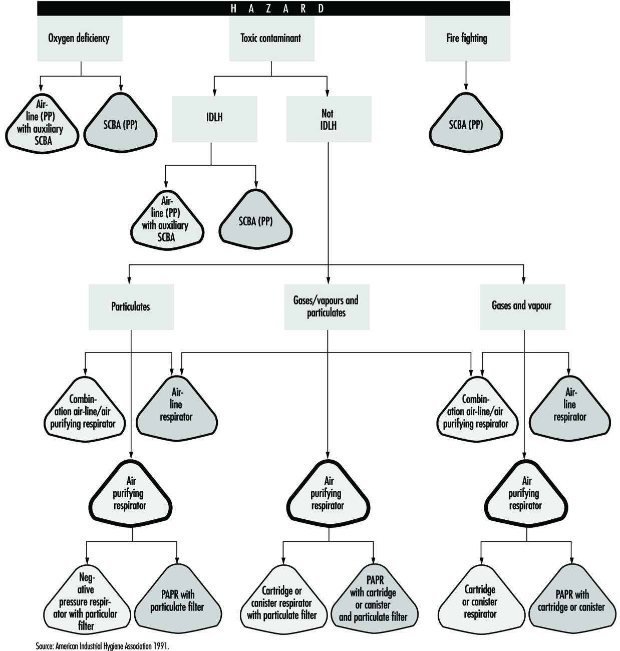
Worker activity and worker location in a hazardous area need to be considered in selecting the proper respirator (for example, whether the worker is in the hazardous area continuously or intermittently during the work shift and whether the work rate is light, medium or heavy). For continuous use and heavy work a lightweight respirator would be preferred.
Environmental conditions and level of effort required of the respirator wearer may affect respirator service life. For example, extreme physical exertion can cause the user to deplete the air supply in a SCBA such that its service life is reduced by half or more.
The period of time that a respirator must be worn is an important factor that has to be taken into account in selecting a respirator. Consideration should be given to the type of task—routine, nonroutine, emergency, or rescue work—that the respirator will be called upon to perform.
The location of the hazardous area with respect to a safe area having respirable air must be considered in selecting a respirator. Such knowledge will permit planning for the escape of workers if an emergency occurs, for the entry of workers to perform maintenance duties and for rescue operations. If there is a long distance to breathable air or if the worker needs to be able to walk around obstacles or climb steps or ladders, then a supplied-air respirator would not be a good choice.
If the potential for an oxygen-deficient environment exists, measure the oxygen content of the relevant work space. The class of respirator, air-purifying or supplied-air, that can be used will depend on the partial pressure of oxygen. Because air-purifying respirators only purify the air, sufficient oxygen must be present in the surrounding atmosphere to support life in the first place.
Respirator selection involves reviewing each operation to ascertain what dangers may be present (hazard determination) and to select the type or class of respirators that can offer adequate protection.
Hazard Determination Steps
In order to determine the properties of the contaminants that may be present in the workplace, one should consult the key source for this information, namely, the supplier of the material. Many suppliers provide their customers with a material safety data sheet (MSDS) which reports the identity of the materials in a product and supplies information on exposure limits and toxicity as well.
One should determine whether there is a published exposure limit such as a threshold limit value (TLV), permissible exposure limit (PEL), maximum acceptable concentration, (MAK), or any other available exposure limit or estimate of toxicity for the contaminants. It ought to be ascertained whether a value for the immediately dangerous to life or health (IDLH) concentration for the contaminant is available. Each respirator has some use limitation based on the level of exposure. A limit of some sort is needed to determine whether the respirator will provide sufficient protection.
Steps should be taken to discover if there is a legally mandated health standard for the given contaminant (as there is for lead or asbestos). If so, there may be specific respirators required that will help narrow the selection process.
The physical state of the contaminant is an important characteristic. If an aerosol, its particle size should be determined or estimated. The vapour pressure of an aerosol is also significant at the maximum expected temperature of the work environment.
One should determine whether the contaminant present can be absorbed through the skin, produce skin sensitization or be irritating or corrosive to the eyes or skin. It should also be found for a gaseous or vapour contaminant if a known odour, taste or irritation concentration exists.
Once the identity of the contaminant is known, its concentration needs to be determined. This is normally done by collecting the material on a sample medium with subsequent analysis by a laboratory. Sometimes the assessment can be accomplished by estimating exposures, as described below.
Estimating Exposure
Sampling is not always required in hazard determination. Exposures can be estimated by examining data relating to similar tasks or by calculation by means of a model. Models or judgment can be used to estimate the likely maximum exposure and this estimate can be used to select a respirator. (The most basic models suitable to such a purpose is the evaporation model, a given amount of material is either assumed or allowed to evaporate into an air space, its vapour concentration found, and an exposure estimated. Adjustments can be made for dilution effects or ventilation.)
Other possible sources of exposure information are articles in journals or trade publications which present exposure data for various industries. Trade associations and data collected in hygiene programmes for similar processes are also useful for this purpose.
Taking protective action based on estimated exposure involves making a judgement based on experience vis-à-vis the type of exposure. For example, air monitoring data of previous tasks will not be useful in the event of the first occurrence of a sudden break in a delivery line. The possibility of such accidental releases must be anticipated in the first place before the need of a respirator can be decided, and the specific type of respirator chosen can then be made on the basis of the estimated likely concentration and nature of the contaminant. For example, for a process involving toluene at room temperatures, a safety device that offers no more protection than a continuous-flow air line need be chosen, since the concentration of toluene would not be expected to exceed its IDLH level of 2,000 ppm. However, in the case of a break in a sulphur dioxide line, a more effective device—say, an air-supplied respirator with an escape bottle—would be called for, since a leak of this sort could quite readily result in an ambient concentration of contaminant above the IDLH level of 20 ppm. In the next section, respirator selection will be examined in further detail.
Specific Respirator Selection Steps
If one is unable to determine what potentially hazardous contaminant may be present, the atmosphere is considered immediately dangerous to life or health. An SCBA or air line with an escape bottle is then required. Similarly, if no exposure limit or guideline is available and estimates of the toxicity cannot be made, the atmosphere is considered IDLH and an SCBA is required. (See the discussion below on the subject of IDLH atmospheres.)
Some countries have very specific standards governing respirators that can be used in given situations for specific chemicals. If a specific standard exists for a contaminant, the legal requirements must be followed.
For an oxygen-deficient atmosphere, the type of respirator selected depends on the partial pressure and concentration of oxygen and the concentration of the other contaminants that may be present.
Hazard ratio and assigned protection factor
The measured or estimated concentration of a contaminant is divided by its exposure limit or guideline to obtain its hazard ratio. With respect to this contaminant, a respirator is selected that has an assigned protection factor (APF) greater than the value of the hazard ratio (the assigned protection factor is the estimated performance level of a respirator). In many countries, a half mask is assigned an APF of ten. It is assumed that the concentration inside the respirator will be reduced by a factor of ten, that is, the APF of the respirator.
The assigned protection factor can be found in any existent regulations on respirator use or in the American National Standard for Respiratory Protection (ANSI Z88.2 1992). ANSI APFs are listed in table 2.
Table 2. Assigned protection factors from ANSI Z88 2 (1992)
|
Type of respirator |
Respiratory inlet covering |
|||
|
Half mask1 |
Full facepiece |
Helmet/hood |
Loose-fitting facepiece |
|
|
Air-Purifying |
10 |
100 |
||
|
Atmosphere-supplying |
||||
|
SCBA (demand-type)2 |
10 |
100 |
||
|
Airline(demand-type) |
10 |
100 |
||
|
Powered air-purifying |
50 |
10003 |
10003 |
25 |
|
Atmosphere-supplying air-line type |
||||
|
Pressure-fed demand type |
50 |
1000 |
— |
— |
|
Continuous Flow |
50 |
1000 |
1000 |
25 |
|
Self-contained breathing apparatus |
||||
|
Positive pressure (demand open/closed circuit) |
— |
4 |
— |
— |
1 Includes one-quarter mask, disposable half masks and half masks with elastomeric facepieces.
2 Demand SCBA shall not be used for emergency situations such as fire fighting.
3 Protection factors listed are for high efficiency filters and sorbents (cartridges and canisters). With dust filters an assigned protection factor of 100 is to be used due to the limitations of the filter.
4 Although positive pressure respirators are currently regarded as providing the highest level of respiratory protection, a limited number of recent simulated workplace studies concluded that all users may not achieve protection factors of 10,000. Based on this limited data, a definitive assigned protection factor could not be listed for positive pressure SCBAs. For emergency planning purposes where hazardous concentrations can be estimated, an assigned protection factor of no higher than 10,000 should be used.
Note: Assigned protection factors are not applicable for escape respirators. For combination respirators, e.g., air-line respirators equipped with an air-purifying filter, the mode of operation in use will dictate the assigned protection factor to be applied.
Source: ANSI Z88.2 1992.
For example, for a styrene exposure (exposure limit of 50 ppm) with all of the measured data at the worksite less than 150 ppm, the hazard ratio is 3 (that is, 150 ¸ 50 = 3). Selection of a half-mask respirator with an assigned protection factor of 10 will assure that most unmeasured data will be well below the assigned limit.
In some cases where “worst-case” sampling is done or only a few data are collected, judgement must be used to decide if enough data have been collected for an acceptably reliable assessment of exposure levels. For example, if two samples were collected for a short-term task that represents the “worst-case” for that task and both samples were less than two times the exposure limit (a hazard ratio of 2), a half-mask respirator (with an APF of 10) would likely be an appropriate choice and certainly a continuous-flow full facepiece respirator (with an APF of 1,000) would be sufficiently protective. The contaminant’s concentration must also be less than the maximum-use concentration of the cartridge/canister: this latter information is available from the manufacturer of the respirator.
Aerosols, gases and vapours
If the contaminant is an aerosol, a filter will have to be used; the choice of filter will depend on the efficiency of the filter for the particle. The literature provided by the manufacturer will provide guidance on the appropriate filter to use. For example, if the contaminant is a paint, lacquer or enamel, a filter designed specifically for paint mists may be used. Other special filters are designed for fumes or dust particles that are larger than usual.
For gases and vapours, adequate notice of cartridge failure is necessary. Odour, taste or irritation are used as indicators that the contaminant has “broken through” the cartridge. Therefore, the concentration at which the odour, taste or irritation is noted must be less than the exposure limit. If the contaminant is a gas or vapour that has poor warning properties, the use of an atmosphere-supplying respirator is generally recommended.
However, atmosphere-supplying respirators sometimes cannot be used because of the lack of an air supply or because of the need for worker mobility. In this case, air-purifying devices may be used, but it is necessary that it be equipped with an indicator signalling the end of the device’s service life so that the user will be given adequate warning prior to contaminant breakthrough. Another alternative is to use a cartridge change schedule. The change schedule is based on cartridge service data, expected concentration, pattern of use and duration of exposure.
Respirator selection for emergency or IDLH conditions
As noted above, IDLH conditions are presumed to exist when the concentration of a contaminant is not known. Furthermore, it is prudent to consider any confined space containing less than 20.9% oxygen as an immediate danger to life or health. Confined spaces present unique hazards. Lack of oxygen in confined spaces is the cause of numerous deaths and serious injuries. Any reduction in the percentage of oxygen present is proof, at a minimum, that the confined space is not adequately ventilated.
Respirators for use under IDLH conditions at normal atmospheric pressure include either a positive-pressure SCBA alone or a combination of a supplied-air respirator with an escape bottle. When respirators are worn under IDLH conditions, at least one standby person must be present in a safe area. The standby person needs to have the proper equipment available to assist the wearer of the respirator in case of difficulty. Communications have to be maintained between the standby person and the wearer. While working in the IDLH atmosphere, the wearer needs to be equipped with a safety harness and safety lines to permit his or her removal to a safe area, if necessary.
Oxygen-deficient atmospheres
Strictly speaking, oxygen deficiency is a matter only of its partial pressure in a given atmosphere. Oxygen deficiency can be caused by a reduction in the percentage of oxygen in the atmosphere or by reduced pressure, or both reduced concentration and pressure. At high altitudes, reduced total atmospheric pressure can lead to very low oxygen pressure.
Humans need a partial oxygen pressure of approximately 95 mm Hg (torr) to survive. The exact pressure will vary among people depending on their health and acclimatization to reduced oxygen pressure. This pressure, 95 mm Hg, is equivalent to 12.5% oxygen at sea level or 21% oxygen at an altitude of 4,270 meters. Such an atmosphere may adversely affect either the person with reduced tolerance to reduced oxygen levels or the unacclimatized person performing work requiring a high degree of mental acuity or heavy stress.
To prevent adverse effects, supplied-air respirators should be provided at higher oxygen partial pressures, for example, about 120 mm Hg or 16% oxygen content at sea level. A physician should be involved in any decisions where people will be required to work in reduced-oxygen atmospheres. There may be legally mandated levels of oxygen percent or partial pressure that require supplied-air respirators at different levels than these broadly general guidelines suggest.
Suggested Procedures for Fit Testing
Each person assigned a tight-fitting negative-pressure respirator needs to be fit tested periodically. Each face is different, and a specific respirator may not fit a given person’s face. Poor fit would allow contaminated air to leak into the respirator, lowering the amount of protection the respirator provides. A fit test needs to be repeated periodically and must be carried out whenever a person has a condition that may interfere with facepiece sealing, e.g., significant scarring in the area of the face seal, dental changes, or reconstructive or cosmetic surgery. Fit testing has to be done while the subject is wearing protective equipment such as spectacles, goggles, a face shield or a welding helmet that will be worn during work activities and could interfere with respirator fit. The respirator should be configured as it will be used, that is, with a chin canister or cartridge.
Fit test procedures
Respirator fit testing is conducted to determine if a particular model and size of mask fits an individual’s face. Before the test is made, the subject should be oriented on the respirator’s proper use and donning, and the test’s purpose and procedures should be explained. The person being tested should understand that the he or she is being asked to select the respirator that provides the most comfortable fit. Each respirator represents a different size and shape and, if fit properly and used properly, will provide adequate protection.
No one size or model of respirator will fit all types of faces. Different sizes and models will accommodate a broader range of facial types. Therefore, an appropriate number of sizes and models should be available from which a satisfactory respirator can be selected.
The person being tested should be instructed to hold each facepiece up to the face and eliminate those which obviously do not give a comfortable fit. Normally, selection will begin with a half mask, and if a good fit cannot be found, the person will need to test a full facepiece respirator. (A small percentage of users will not be able to wear any half mask.)
The subject should conduct a negative- or positive-pressure fit check according to the instructions provided by the manufacturer before the test is begun. The subject is now ready for fit testing by one of the methods listed below. Other fit test methods are available, including quantitative fit test methods which use instruments to measure leakage into the respirator. The fit test methods, which are outlined in the boxes here, are qualitative and do not require expensive test equipment. These are (1) the isoamyl acetate (IAA) protocol and (2) the saccharin solution aerosol protocol.
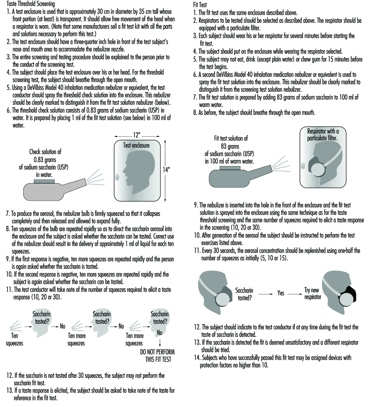
Test exercises. During the fit test, the wearer should carry out a number of exercises in order to verify that the respirator will allow him or her to perform a set of basic and necessary actions. The following six exercises are recommended: standing still, breathing normally, breathing deeply, moving the head from side to side, moving the head up and down, and speaking. (See figure 2 and figure 3).
Figure 2. Isoamly acetate quantitive fit-test method
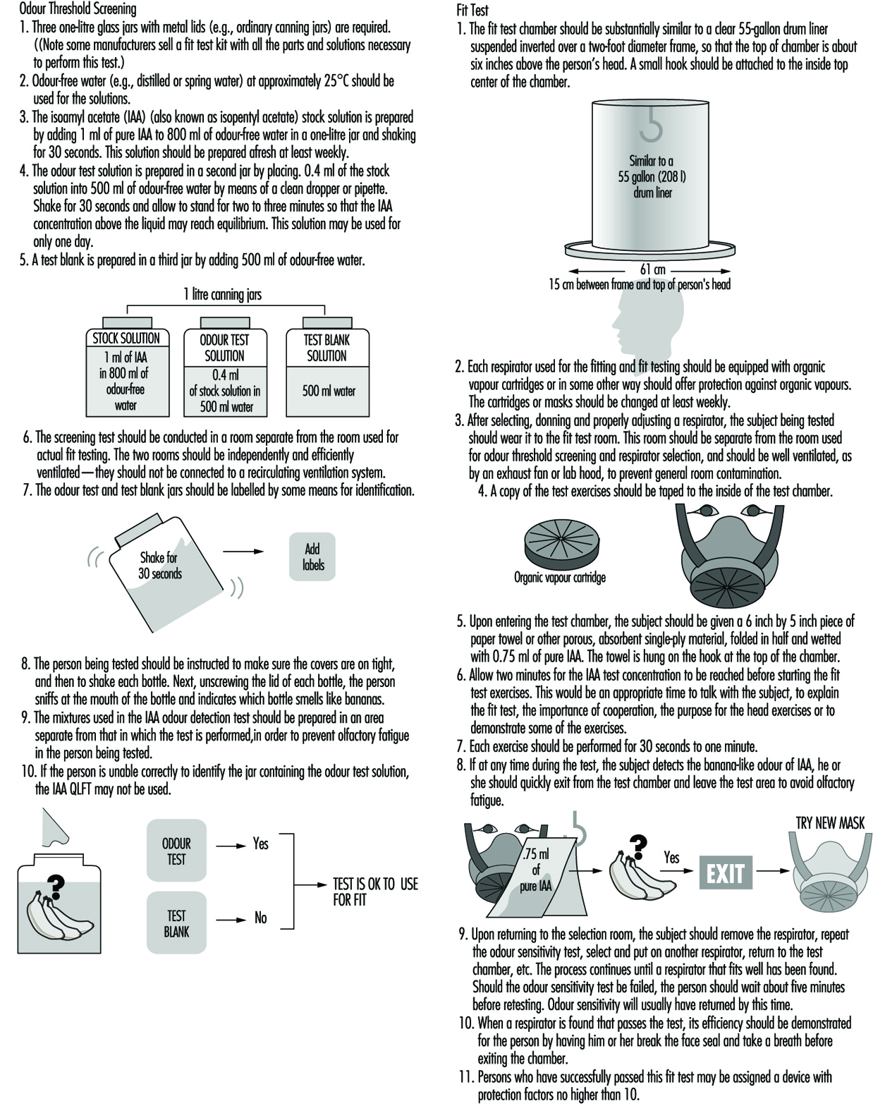
Figure 3. Sacharin aerosol quantitive fit-test method
Protective Clothing
Hazards
There are several general categories of bodily hazards for which specialized clothing can provide protection. These general categories include chemical, physical and biological hazards. Table 1 summarizes these.
Table 1. Examples of dermal hazard categories
|
Hazard |
Examples |
|
Chemical |
Dermal toxins |
|
Physical |
Thermal hazards (hot/cold) |
|
Biological |
Human pathogens |
Chemical hazards
Protective clothing is a commonly used control to reduce worker exposures to potentially toxic or hazardous chemicals when other controls are not feasible. Many chemicals pose more than one hazard (for example, a substance such as benzene is both toxic and flammable). For chemical hazards, there are at least three key considerations that need attention. These are (1) the potential toxic effects of exposure, (2) likely routes of entry, and (3) the exposure potentials associated with the work assignment. Of the three aspects, toxicity of the material is the most important. Some substances simply present a cleanliness problem (e.g., oil and grease) while other chemicals (e.g., contact with liquid hydrogen cyanide) could present a situation which is immediately dangerous to life and health (IDLH). Specifically, the toxicity or hazardousness of the substance by the dermal route of entry is the critical factor. Other adverse effects of skin contact, besides toxicity, include corrosion, promotion of cancer of the skin and physical trauma such as burns and cuts.
An example of a chemical whose toxicity is greatest by the dermal route is nicotine, which has excellent skin permeability but is not generally an inhalation hazard (except when self-administered). This is only one of many instances where the dermal route offers a much more significant hazard than the other routes of entry. As suggested above, there are many substances that are not generally toxic but are hazardous to the skin because of their corrosive nature or other properties. In fact, some chemicals and materials can offer an even greater acute risk through skin absorption than the most dreaded systemic carcinogens. For example, a single unprotected skin exposure to hydrofluoric acid (above 70% concentration) can be fatal. In this case, as little as a 5% surface burn typically results in death from the effects of the fluoride ion. Another example of a dermal hazard—though not an acute one—is the promotion of skin cancer by substances such as coal tars. An example of a material which has high human toxicity but little skin toxicity is inorganic lead. In this case the concern is contamination of the body or clothing, which could later lead to ingestion or inhalation, since the solid will not permeate intact skin.
Once an evaluation of the routes of entry and toxicity of the materials has been completed, an assessment of the likelihood of exposure needs to be carried out. For example, do workers have enough contact with a given chemical to become visibly wet or is exposure unlikely and protective clothing intended to act simply as a redundant control measure? For situations where the material is deadly although the likelihood of contact is remote, the worker must obviously be provided with the highest level of protection available. For situations where the exposure itself represents a very minimal risk (e.g., a nurse handling 20% isopropyl alcohol in water), the level of protection does not need to be fail-safe. This selection logic is essentially based on an estimate of the adverse effects of the material combined with an estimate of the likelihood of exposure.
The chemical resistance properties of barriers
Research showing the diffusion of solvents and other chemicals through “liquid-proof” protective clothing barriers has been published from the 1980s to the 1990s. For example, in a standard research test, acetone is applied to neoprene rubber (of typical glove thickness). After direct acetone contact on the normal outside surface, the solvent can normally be detected on the inside surface (the skin side) within 30 minutes, although in small quantities. This movement of a chemical through a protective clothing barrier is called permeation. The permeation process consists of the diffusion of chemicals on a molecular level through the protective clothing. Permeation occurs in three steps: absorption of the chemical at the barrier surface, diffusion through the barrier, and desorption of the chemical on the normal inside surface of the barrier. The time elapsed from the initial contact of the chemical on the outside surface until detection on the inside surface is called the breakthrough time. The permeation rate is the steady-state rate of movement of the chemical through the barrier after equilibrium is reached.
Most current testing of permeation resistance extends over periods of up to eight hours, reflecting normal work shifts. However, these tests are conducted under conditions of direct liquid or gaseous contact that typically do not exist in the work environment. Some would therefore argue that there is a significant “safety factor” built into the test. Countering this assumption are the facts that the permeation test is static while the work environment is dynamic (involving flexing of materials or pressures generated from gripping or other movement) and that there may exist prior physical damage to the glove or garment. Given the lack of published skin permeability and dermal toxicity data, the approach taken by most safety and health professionals is to select the barrier with no breakthrough for the duration of the job or task (usually eight hours), which is essentially a no-dose concept. This is an appropriately conservative approach; however, it is important to note that there is no protective barrier currently available which provides permeation resistance to all chemicals. For situations where the breakthrough times are short, the safety and health professional should select the barriers with the best performance (i.e., with the lowest permeation rate) while considering other control and maintenance measures as well (such as the need for regular clothing changes).
Aside from the permeation process just described, there are two other chemical resistance properties of concern to the safety and health professional. These are degradation and penetration. Degradation is a deleterious change in one or more of the physical properties of a protective material caused by contact with a chemical. For example, the polymer polyvinyl alcohol (PVA) is a very good barrier to most organic solvents, but is degraded by water. Latex rubber, which is widely used for medical gloves, is of course water resistant, but is readily soluble in such solvents as toluene and hexane: it would be plainly ineffective for protection against these chemicals. Secondly, latex allergies can cause severe reactions in some people.
Penetration is the flow of a chemical through pinholes, cuts or other imperfections in protective clothing on a nonmolecular level. Even the best protective barriers will be rendered ineffective if punctured or torn. Penetration protection is important when the exposure is unlikely or infrequent and the toxicity or hazard is minimal. Penetration is usually a concern for garments used in splash protection.
Several guides have been published listing chemical resistance data (many are also available in an electronic format). In addition to these guides, most manufacturers in the industrially developed countries also publish current chemical and physical resistance data for their products.
Physical hazards
As noted in table 1, physical hazards include thermal conditions, vibration, radiation and trauma as all having the potential to affect the skin adversely. Thermal hazards include the adverse effects of extreme cold and heat on the skin. The protective attributes of clothing with respect to these hazards is related to its degree of insulation, whereas protective clothing for flash fire and electric flashover requires flame resistance properties.
Specialized clothing can provide limited protection from some forms of both ionizing and non-ionizing radiation. In general, the effectiveness of clothing that protects against ionizing radiation is based on the principle of shielding (as with lead-lined aprons and gloves), whereas clothing employed against non-ionizing radiation, such as microwave, is based on grounding or isolation. Excessive vibration can have several adverse effects on body parts, primarily the hands. Mining (involving hand-held drills) and road repair (for which pneumatic hammers or chisels are used), for example, are occupations where excessive hand vibration can lead to bone degeneration and loss of circulation in the hands. Trauma to the skin from physical hazards (cuts, abrasions, etc.) is common to many occupations, with construction and meat cutting as two examples. Specialized clothing (including gloves) are now available which are cut-resistant and are used in applications such as meat cutting and forestry (using chain saws). These are based either on inherent cut-resistance or the presence of enough fibre mass to clog moving parts (e.g., chain saws).
Biological hazards
Biological hazards include infection due to agents and disease common to humans and animals, and the work environment. Biological hazards common to humans have received great attention with the increasing spread of blood-borne AIDS and hepatitis. Hence, occupations which might involve exposure to blood or body fluids usually require some type of liquid-resistant garment and gloves. Diseases transmitted from animals through handling (e.g., anthrax) have a long history of recognition and require protective measures similar to those used for handling the kind of blood-borne pathogens that affect humans. Work environments that can present a hazard due to biological agents include clinical and microbiological laboratories as well as other special work environments.
Types of Protection
Protective clothing in a generic sense includes all elements of a protective ensemble (e.g., garments, gloves and boots). Thus, protective clothing can include everything from a finger cot providing protection against paper cuts to a fully encapsulating suit with a self-contained breathing apparatus used for an emergency response to a hazardous chemical spill.
Protective clothing can be made of natural materials (e.g., cotton, wool and leather), man-made fibres (e.g., nylon) or various polymers (e.g., plastics and rubbers such as butyl rubber, polyvinyl chloride, and chlorinated polyethylene). Materials which are woven, stitched or are otherwise porous (not resistant to liquid penetration or permeation) should not be used in situations where protection against a liquid or gas is required. Specially treated or inherently non-flammable porous fabrics and materials are commonly used for flash fire and electric arc (flashover) protection (e.g., in the petrochemical industry) but usually do not provide protection from any regular heat exposure. It should be noted here that fire-fighting requires specialized clothing that provides flame (burning) resistance, a water barrier and thermal insulation (protection from high temperatures). Some special applications also require infrared (IR) protection by use of aluminized overcovers (e.g., fighting petroleum fuel fires). Table 2 summarizes typical physical, chemical, and biological performance requirements and common protective materials used for hazard protection.
Table 2. Common physical, chemical and biological performance requirements
|
Hazard |
Performance characteristic required |
Common protective clothing materials |
|
Thermal |
Insulation value |
Heavy cotton or other natural fabrics |
|
Fire |
Insulation and flame resistance |
Aluminized gloves; flame resistent treated gloves; aramid fibre and other special fabrics |
|
Mechanical abrasion |
Abrasion resistence; tensile strength |
Heavy fabrics; leather |
|
Cuts and punctures |
Cut resistance |
Metal mesh; aromatic polyamide fiber and other special fabrics |
|
Chemical/toxicological |
Permeation resistance |
Polymeric and elastomeric materials; (including latex) |
|
Biological |
“Fluid-proof”; (puncture resistant) |
|
|
Radiological |
Usually water resistance or particle resistance (for radionuclides) |
Protective clothing configurations vary greatly depending on the intended use. However, normal components are analogous to personal clothing (i.e., trousers, jacket, hood, boots and gloves) for most physical hazards. Special-use items for applications such as flame resistance in those industries involving the processing of molten metals can include chaps, armlets, and aprons constructed of both treated and untreated natural and synthetic fibres and materials (one historical example would be woven asbestos). Chemical protective clothing can be more specialized in terms of construction, as shown in figure 1 and figure 2.
Figure 1. A worker wearing gloves and a chemically protective garment pouring chemical
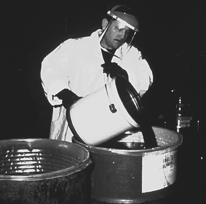
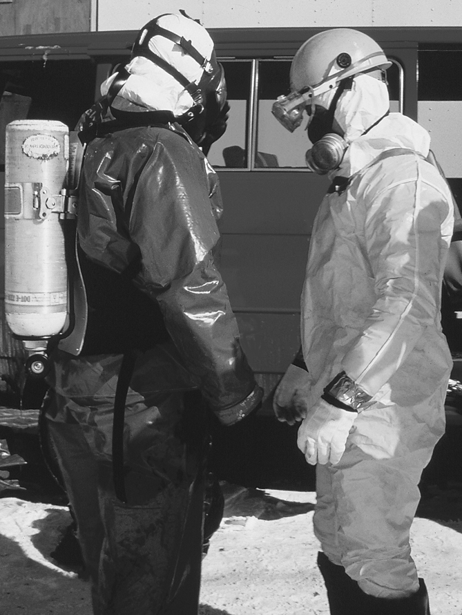
Figure 2. Two workers in differing configurations of chemical protective clothing
Chemically protective gloves are usually available in a wide variety of polymers and combinations; some cotton gloves, for example, are coated by the polymer of interest (by means of a dipping process). (See figure 3). Some of the new foil and multilaminate “gloves” are only two-dimensional (flat)—and hence have some ergonomic constraints, but are highly chemical resistant. These gloves typically work best when a form-fitting outer polymer glove is worn over the top of the inner flat glove (this technique is called double gloving) to conform the inner glove to the shape of the hands. Polymer gloves are available in a wide variety of thicknesses ranging from very light weight (<2 mm) to heavy weight (>5 mm) with and without inner liners or substrates (called scrims). Gloves are also commonly available in a variety of lengths ranging from approximately 30 centimetres for hand protection to gauntlets of approximately 80 centimetres, extending from the worker’s shoulder to the tip of the hand. The correct choice of length depends on the extent of protection required; however, the length should normally be sufficient to extend at least to the worker’s wrists so as to prevent drainage into the glove. (See figure 4).
Figure 3. Various types of chemically resistant gloves
MISSING
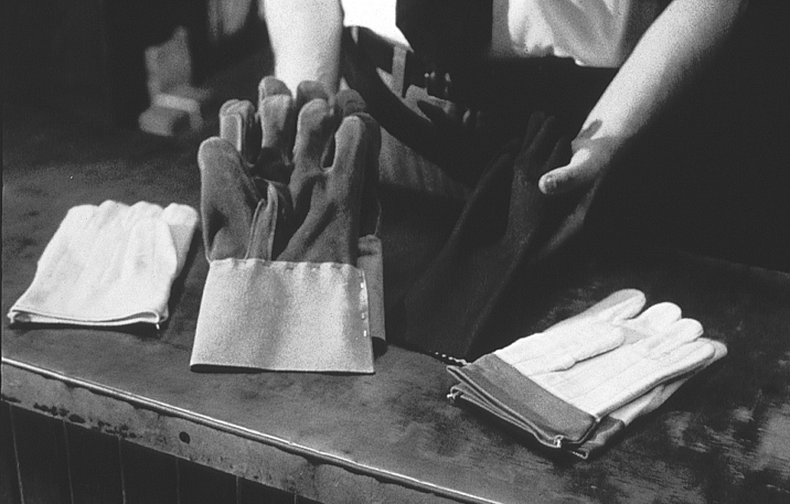
Figure 4. Natural-fibre gloves; also illustrates sufficient length for wrist protection
Boots are available in a wide variety of lengths ranging from hip length to those that cover only the bottom of the foot. Chemical protective boots are available in only a limited number of polymers since they require a high degree of abrasion resistance. Common polymers and rubbers used in chemically resistant boot construction include PVC, butyl rubber and neoprene rubber. Specially constructed laminated boots using other polymers can also be obtained but are quite expensive and in limited supply internationally at the present time.
Chemical protective garments can be obtained as a one-piece fully encapsulating (gas-tight) garment with attached gloves and boots or as multiple components (e.g., trousers, jacket, hoods, etc.). Some protective materials used for construction of ensembles will have multiple layers or laminas. Layered materials are generally required for polymers that do not have good enough inherent physical integrity and abrasion resistance properties to permit manufacture and use as a garment or glove (e.g., butyl rubber versus Teflon®). Common support fabrics are nylon, polyester, aramides and fibreglass. These substrates are coated or laminated by polymers such as polyvinyl chloride (PVC), Teflon®, polyurethane and polyethylene.
Over the last decade there has been an enormous growth in the use of nonwoven polyethene and microporous materials for disposable suit construction. These spun-bonded suits, sometimes incorrectly called “paper suits,” are made using a special process whereby the fibres are bonded together rather than woven. These protective garments are low in cost and very light in weight. Uncoated microporous materials (called “breathable” because they allow some water vapour transmission and hence are less heat stressful) and spun-bonded garments have good applications as protection against particulates but are not normally chemical-or liquid-resistant. Spun-bonded garments are also available with various coatings such as polyethylene and Saranex®. Depending on the coating characteristics, these garments can offer good chemical resistance to most common substances.
Approval, Certification and Standards
The availability, construction, and design of protective clothing varies greatly throughout the world. As might be expected, approval schemes, standards and certifications also vary. Nevertheless, there are similar voluntary standards for performance throughout the United States (e.g., American Society for Testing and Materials—ASTM—standards), Europe (European Committee for Standardization—CEN—standards), and for some parts of Asia (local standards such as in Japan). The development of worldwide performance standards has begun through the International Organization for Standardization Technical Committee 94 for Personal Safety-Protective Clothing and Equipment. Many of the standards and test methods to measure performance developed by this group were based on either CEN standards or those from other countries such as the United States through the ASTM.
In the United States, Mexico, and most of Canada, no certification or approvals are required for most protective clothing. Exceptions exist for special applications such as pesticide applicators clothing (governed by pesticide labelling requirements). Nevertheless, there are many organizations that issue voluntary standards, such as the previously mentioned ASTM, the National Fire Protection Association (NFPA) in the United States and the Canadian Standards Organization (CSO) in Canada. These voluntary standards do significantly affect the marketing and sale of protective clothing and hence act much like mandated standards.
In Europe, the manufacturing of personal protective equipment is regulated under the European Community Directive 89/686/EEC. This directive both defines which products fall within the scope of the directive and classifies them into different categories. For categories of protective equipment where the risk is not minimal and where the user cannot readily identify the hazard easily, the protective equipment must meet standards of quality and manufacture detailed in the directive.
No protective equipment products may be sold within the European Community unless they have the CE (European Community) mark. Testing and quality assurance requirements must be followed to receive the CE mark.
Individual Capabilities and Needs
In all but a few cases, the addition of protective clothing and equipment will decrease productivity and increase worker discomfort. It may also lead to decreased quality, since error rates increase with the use of protective clothing. For chemical protective and some fire-resistant clothing there are some general guidelines that need to be considered concerning the inherent conflicts between worker comfort, efficiency and protection. First, the thicker the barrier the better (increases the time to breakthrough or provides greater thermal insulation); however, the thicker the barrier the more it will decrease ease of movement and user comfort. Thicker barriers also increase the potential for heat stress. Second, barriers which have excellent chemical resistance tend to increase the level of worker discomfort and heat stress because the barrier normally will also act as a barrier to water vapour transmission (i.e., perspiration). Third, the higher the overall protection of the clothing, the more time a given task will take to accomplish and the greater the chance of errors. There are also a few tasks where the use of protective clothing could increase certain classes of risk (e.g., around moving machinery, where the risk of heat stress is greater than the chemical hazard). While this situation is rare, it must be considered.
Other issues relate to the physical limitations imposed by using protective clothing. For example, a worker issued a thick pair of gloves will not be able to perform tasks easily that require a high degree of dexterity and repetitive motions. As another example, a spray painter in a totally encapsulating suit will usually not be able to look to the side, up or down, since typically the respirator and suit visor restrict the field of vision in these suit configurations. These are only some examples of the ergonomic restrictions associated with wearing protective clothing and equipment.
The work situation must always be considered in the selection of the protective clothing for the job. The optimum solution is to select the minimum level of protective clothing and equipment that is necessary to do the job safely.
Education and Training
Adequate education and training for users of protective clothing is essential. Training and education should include:
- the nature and extent of the hazards
- the conditions under which protective clothing should be worn
- what protective clothing is necessary
- the use and limitations of the protective clothing to be assigned
- how to inspect, don, doff, adjust and wear the protective clothing properly
- decontamination procedures, if necessary
- signs and symptoms of overexposure or clothing failure
- first aid and emergency procedures
- the proper storage, useful life, care and disposal of protective clothing.
This training should incorporate at least all of the elements listed above and any other pertinent information that has not already been provided to the worker through other programmes. For those topical areas already provided to the worker, a refresher summary should still be provided for the clothing user. For example, if the signs and symptoms of overexposure have already been indicated to the workers as part of their training for working with chemicals, symptoms that are a result of significant dermal exposures versus inhalation should be reemphasized. Finally, the workers should have an opportunity to try out the protective clothing for a particular job before a final selection is made.
Knowledge of the hazard and of the limitations of the protective clothing not only reduces the risk to the worker but also provides the health and safety professional with a worker capable of providing feedback on the effectiveness of the protective equipment.
Maintenance
The proper storage, inspection, cleaning and repair of protective clothing is important to the overall protection provided by the products to the wearer.
Some protective clothing will have storage limitations such as a prescribed shelf life or required protection from UV radiation (e.g., sunlight, welding flash, etc.), ozone, moisture, temperature extremes or prevention of product folding. For example, natural rubber products usually call for all of the precautionary measures just listed. As another example, many of the encapsulating polymer suits can be damaged if folded rather than allowed to hang upright. The manufacturer or distributor should be consulted for any storage limitations their products may have.
Inspection of protective clothing should be performed by the user on a frequent basis (e.g., with each use). Inspection by co-workers is another technique which may be used to involve wearers in ensuring the integrity of the protective clothing they have to use. As a management policy, it is also advisable to require supervisors to inspect protective clothing (at appropriate intervals) that is used on a routine basis. Inspection criteria will depend on the intended use of the protective item; however, it would normally include examination for tears, holes, imperfections and degradation. As one example of an inspection technique, polymer gloves used for protection against liquids should be blown up with air to check for integrity against leaks.
Cleaning of protective clothing for reuse must be performed with care. Natural fabrics can be cleaned by normal washing methods if they are not contaminated with toxic materials. Cleaning procedures suitable for synthetic fibres and materials are commonly limited. For example, some products treated for flame resistance will lose their effectiveness if not properly cleaned. Clothing used for protection against chemicals which are not water-soluble often cannot be decontaminated by washing with simple soap or detergent and water. Tests performed on pesticide applicators’ clothing indicate that normal washing procedures are not effective for many pesticides. Dry cleaning is not recommended at all since it is often ineffective and can degrade or contaminate the product. It is important to consult the manufacturer or distributor of the clothing before attempting cleaning procedures that are not specifically known to be safe and workable.
Most protective clothing is not repairable. Repairs can be made on some few items such as fully encapsulating polymer suits. However, the manufacturer should be consulted for the proper repair procedures.
Use and Misuse
Use. First and foremost, the selection and proper use of protective clothing should be based on an assessment of the hazards involved in the task for which the protection is required. In light of the assessment, an accurate definition of the performance requirements and the ergonomic constraints of the job can be determined. Finally, a selection that balances worker protection, ease of use and cost can be made.
A more formal approach would be to develop a written model programme, a method that would reduce the chance of error, increase worker protection and establish a consistent approach to the selection and use of protective clothing. A model programme could contain the following elements:
- an organization scheme and administrative plan
- a risk assessment methodology
- an evaluation of other control options to protect the worker
- performance criteria for the protective clothing
- selection criteria and procedures to determine the optimum choice
- purchasing specifications for the protective clothing
- a validation plan for the selection made
- decontamination and reuse criteria, as applicable
- a user training programme
- 10.an auditing plan to assure that procedures are consistently followed.
Misuse. There are several examples of misuse of protective clothing that can commonly be seen in industry. Misuse is usually the result of a lack of understanding of the limitations of protective clothing on the part of management, of the workers, or of both. A clear example of bad practice is the use of nonflame-resistant protective clothing for workers who handle flammable solvents or who work in situations where open flames, burning coals or molten metals are present. Protective clothing made of polymeric materials such as polyethylene may support combustion and can actually melt into the skin, causing an even more severe burn.
A second common example is the reuse of protective clothing (including gloves) where the chemical has contaminated the inside of the protective clothing so that the worker increases his or her exposure on each subsequent use. One frequently sees another variation of this problem when workers use natural-fibre gloves (e.g., leather or cotton) or their own personal shoes to work with liquid chemicals. If chemicals are spilled on the natural fibres, they will be retained for long periods of time and migrate to the skin itself. Yet another variation of this problem is taking contaminated work clothing home for cleaning. This can result in the exposure of an entire family to harmful chemicals, a common problem because the work clothing is usually cleaned with the other articles of clothing of the family. Since many chemicals are not water-soluble, they can be spread to other articles of clothing simply by mechanical action. Several cases of this spread of contaminants have been noted, especially in industries which manufacture pesticides or process heavy metals (e.g., poisoning families of workers handling mercury and lead). These are only a few of the more prominent examples of the misuse of protective clothing. These problems can be overcome by simply understanding the proper use and limitations of the protective clothing. This information should be readily available from the manufacturer and health and safety experts.
Hearing Protection
Hearing Protectors
No one knows when people first discovered that covering the ears with the flats of the hands or plugging up the ear canals with one’s fingers was effective in reducing the level of unwanted sound—noise—but the basic technique has been in use for generations as the last line of defence against loud sound. Unfortunately, this level of technology precludes the use of most others. Hearing protectors, an obvious solution to the problem, are a form of noise control in that they block the path of the noise from the source to the ear. They come in various forms, as depicted in figure 1.
Figure 1. Examples of different types of hearing protectors
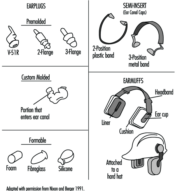
An earplug is a device worn in the external ear canal. Premolded earplugs are available in one or more standard sizes intended to fit into the ear canals of most people. A formable, user-molded earplug is made of a pliable material that is shaped by the wearer to fit into the ear canal to form an acoustic seal. A custom-molded earplug is individually made to fit the particular ear of the wearer. Earplugs can be made from vinyl, silicone, elastomer formulations, cotton and wax, spun glass wool, and slow-recovery closed-cell foam.
A semi-insert earplug, also called an ear-canal cap, is worn against the opening of the external ear canal: the effect is similar to plugging one’s ear canal with a fingertip. Semi-insert devices are manufactured in one size and are designed to fit most ears. This sort of device is held in place by a lightweight headband with mild tension.
An earmuff is a device composed of a headband and two circumaural cups that are usually made of plastic. The headband may be made of metal or plastic. The circumaural ear cup completely encloses the outer ear and seals against the side of the head with a cushion. The cushion may be made of foam or it may be filled with fluid. Most earmuffs have a lining inside the ear cup to absorb the sound that is transmitted through the shell of the ear cup in order to improve the attenuation above approximately 2,000 Hz. Some earmuffs are designed so that the headband may be worn over the head, behind the neck or under the chin, although the amount of protection they afford may be different for each headband position. Other earmuffs are designed to fit on “hard hats.” These may offer less protection because the hard-hat attachment makes it more difficult to adjust the earmuff and they do not fit as wide a range of head sizes as do those with headbands.
In the United States there are 53 manufacturers and distributors of hearing protectors who, as of July 1994, sold 86 models of earplugs, 138 models of earmuffs, and 17 models of semi-insert hearing protectors. In spite of the diversity of hearing protectors, foam earplugs designed for one-time use account for more than half of the hearing protectors in use in the United States.
Last line of defence
The most effective way to avoid noise-induced hearing loss is to stay out of hazardous noise areas. In many work settings it is possible to redesign the manufacturing process so that operators work in enclosed, sound-attenuating control rooms. The noise is reduced in these control rooms to the point where it is not hazardous and where speech communication is not impaired. The next most effective way to avoid noise-induced hearing loss is to reduce the noise at the source so that it is no longer hazardous. This is often done by designing quiet equipment or retrofitting noise control devices to existing equipment.
When it is not possible to avoid the noise or to reduce the noise at the source, hearing protection becomes the last resort. As the last line of defence, having no backup, its effectiveness can often be abridged.
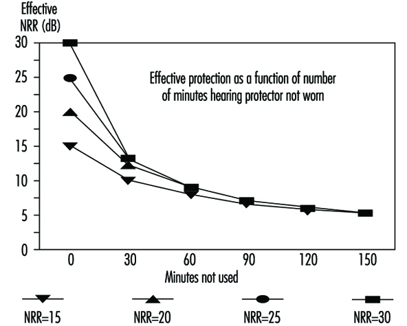
One of the ways to diminish the effectiveness of hearing protectors is to use them less than 100% of the time. Figure 2 shows what happens. Eventually, no matter how much protection is afforded by design, protection is reduced as percent of wearing time decreases. Wearers who remove an earplug or lift an earmuff to talk with fellow workers in noisy environments can severely reduce the amount of protection they receive.
Figure 2. Decrease in effective protection as time of non-use during an 8-hour day increases (based on 3-dB exchange rate)
The Rating Systems and How to Use Them
There are many ways to rate hearing protectors. The most common methods are the single-number systems such as the Noise Reduction Rating (NRR) (EPA 1979) used in the United States and the Single Number Rating (SNR), used in Europe (ISO 1994). Another European rating method is the HML (ISO 1994) that uses three numbers to rate protectors. Finally, there are methods based on the attenuation of the hearing protectors for each of the octave bands, called the long or octave-band method in the United States and the assumed protection value method in Europe (ISO 1994).
All of these methods use the real-ear attenuation at threshold values of the hearing protectors as determined in laboratories according to relevant standards. In the United States, attenuation testing is done in accordance with ANSI S3.19, Method for the Measurement of Real-Ear Protection of Hearing Protectors and Physical Attenuation of Earmuffs (ANSI 1974). Although this standard has been replaced by a newer one (ANSI 1984), the US Environmental Protection Agency (EPA) controls the NRR on hearing protector labels and requires the older standard to be used. In Europe attenuation testing is done in accordance with ISO 4869-1 (ISO 1990).
In general, the laboratory methods require that sound-field hearing thresholds be determined both with the protectors fitted and with the ears open. In the United States the hearing protector must be fitted by the experimenter, while in Europe the subject, assisted by the experimenter, performs this task. The difference between the protectors-fitted and ears-open sound field thresholds is the real-ear attenuation at threshold. Data are collected for a group of subjects, presently ten in the United States with three trials each and 16 in Europe with one trial each. The average attenuation and associated standard deviations are calculated for each octave band tested.
For purposes of discussion, the NRR method and the long method are described and illustrated in table 1.
Table 1. Example calculation of the Noise Reduction Rating (NRR) of a hearing protector
Procedure:
- Tabulate the sound pressure levels of pink noise, arbitrarily set for simplicity of computation to a level of 100 dB in each octave band.
- Tabulate the adjustments for the C-weighting scale at each octave-band centre frequency.
- Add lines 1 and 2 to obtain the C-weighted octave-band levels and logarithmically combine the C-weighted octave-band levels to determine the C-weighted sound pressure level.
- Tabulate the adjustments for the A-weighting scale at each octave-band centre frequency.
- Add line 1 and line 4 to obtain the A-weighted octave-band levels.
- Tabulate the attenuation provided by the device.
- Tabulate the standard deviations of attenuation (times 2) provided by the device.
- Subtract the values of the mean attenuations (step 6) and add the values of the standard deviations times 2 (step 7) to the A-weighted values (step 5) to obtain the estimated A-weighted octave-band sound levels under the device as it was fitted and tested in the laboratory. Combine the A-weighted octave-band levels logarithmically to obtain the A-weighted sound level effective when the device is worn.
- Subtract the A-weighted sound pressure level (step 8) and a 3-dB safety factor from the C-weighted sound pressure level (step 3) to obtain the NRR.
|
Steps |
Octave-band center frequency in Hz |
|||||||
|
125 |
250 |
500 |
1000 |
2000 |
4000 |
8000 |
dBX |
|
|
1. Assumed octave-band level of noise |
100.0 |
100.0 |
100.0 |
100.0 |
100.0 |
100.0 |
100.0 |
|
|
2. C-weighting correction |
–0.2 |
0.0 |
0.0 |
0.0 |
–0.2 |
–0.8 |
–3.0 |
|
|
3. C-weighted octave-band levels |
99.8 |
100.0 |
100.0 |
100.0 |
99.8 |
99.2 |
97.0 |
107.9 dBC |
|
4. A-weighting correction |
–16.1 |
–8.6 |
–3.2 |
0.0 |
+1.2 |
+1.0 |
–1.1 |
|
|
5. A-weighted octave-band levels |
83.9 |
91.4 |
96.8 |
100.0 |
101.2 |
101.0 |
98.9 |
|
|
6. Attenuation of hearing protector |
27.4 |
26.6 |
27.5 |
27.0 |
32.0 |
46.01 |
44.22 |
|
|
7. Standard deviation × 2 |
7.8 |
8.4 |
9.4 |
6.8 |
8.8 |
7.33 |
12.84 |
|
|
8. Estimated protected A-weighted octave band levels |
64.3 |
73.2 |
78.7 |
79.8 |
78.0 |
62.3 |
67.5 |
84.2 dBA |
|
9. NRR = 107.9 – 84.2 – 3 = 20.7 (Step 3 – Step 8 – 3 dB5 ) |
||||||||
1 Mean attenuation at 3000 and 4000 Hz.
2 Mean attenuation at 6000 and 8000 Hz.
3 Sum of standard deviations at 3000 and 4000 Hz.
4 Sum of standard deviations at 6000 and 8000 Hz.
5 The 3-dB correction factor is intended to account for spectrum uncertainty in that the noise in which the hearing protector is to be worn may deviate from the pink-noise spectrum used to calculate the NRR.
The NRR may be used to determine the protected noise level, that is, the effective A-weighted sound pressure level at the ear, by subtracting it from the C-weighted environmental noise level. Thus, if the C-weighted environmental noise level was 100 dBC and the NRR for the protector was 21 dB, the protected noise level would be 79 dBA (100–21 = 79). If only the A-weighted environmental noise level is known, a 7-dB correction is used (Franks, Themann and Sherris 1995). So, if the A-weighted noise level was 103 dBA, the protected noise level would be 89 dBA (103–[21-7] = 89).
The long method requires that the octave-band environmental noise levels be known; there is no shortcut. Many modern sound level meters can simultaneously measure octave-band, C-weighted and A-weighted environmental noise levels. However, no dosimeters currently provide octave-band data. Calculation by the long method is described below and shown in table 2.
Table 2. Example of the long method for computing the A-weighted noise reduction for a hearing protector in a known environmental noise
Procedure:
- Tabulate the measured octave-band levels of the environmental noise.
- Tabulate the adjustments for A-weighting at each octave-band centre frequency.
- Add the results of steps 1 and 2 to obtain the A-weighted octave-band levels. Combine the A-weighted octave-band levels logarithmically to obtain the A-weighted environmental noise level.
- Tabulate the attenuation provided by the device for each octave band.
- Tabulate the standard deviations of attenuation (times 2) provided by the device for each octave band.
- Obtain the A-weighted octave-band levels under the protector by subtracting the mean attenuation (step 4) from the A-weighted octave-band levels (step 3), and adding the standard deviation of the attenuations times 2 (step 5). The A-weighted octave band levels are combined logarithmically to obtain the A-weighted sound level effective when the hearing protector is worn. The estimated A-weighted noise reduction in a given environment is calculated by subtracting the A-weighted sound level under the protector from the A-weighted environmental noise level (the result of step 3 minus that of step 6).
|
Steps |
Octave-band center frequency in Hz |
|||||||
|
125 |
250 |
500 |
1000 |
2000 |
4000 |
8000 |
dBA |
|
|
1. Measured octave-band levels of noise |
85.0 |
87.0 |
90.0 |
90.0 |
85.0 |
82.0 |
80.0 |
|
|
2. A-weighting correction |
–16.1 |
–8.6 |
–3.2 |
0.0 |
+1.2 |
+1.0 |
–1.1 |
|
|
3. A-weighted octave-band levels |
68.9 |
78.4 |
86.8 |
90.0 |
86.2 |
83.0 |
78.9 |
93.5 |
|
4. Attenuation of hearing protector |
27.4 |
26.6 |
27.5 |
27.0 |
32.0 |
46.01 |
44.22 |
|
|
5. Standard deviation × 2 |
7.8 |
8.4 |
9.4 |
6.8 |
8.8 |
7.33 |
12.84 |
|
|
6. Estimated protected |
49.3 |
60.2 |
68.7 |
69.8 |
63.0 |
44.3 |
47.5 |
73.0 |
1 Mean attenuation at 3000 and 4000 Hz.
2 Mean attenuation at 6000 and 8000 Hz.
3 Sum of standard deviations at 3000 and 4000 Hz.
4 Sum of standard deviations at 6000 and 8000 Hz.
The subtractive standard deviation corrections in the long method and in the NRR computations are intended to use the laboratory variability measurements to adjust the estimates of protection to correspond to values expected for most of the users (98% with a 2-standard-deviation correction or 84% if a 1-standard-deviation correction is used) who wear the hearing protector under conditions identical to those involved in the testing. The appropriateness of this adjustment is, of course, heavily dependent upon the validity of the laboratory-estimated standard deviations.
Comparison of the long method and the NRR
The long method and the NRR computations may be compared by subtracting the NRR (20.7) from the C-weighted sound pressure level for the spectrum in table 2 (95.2 dBC) to predict the effective level when the hearing protector is worn, namely 74.5 dBA. This compares favourably to the value of 73.0 dBA derived from the long method in table 2. Part of the disparity between the two estimates is due to the use of the approximate 3 dB spectral safety factor incorporated in line 9 of table 1. The spectral safety factor is intended to account for errors arising from the use of an assumed noise instead of an actual noise. Depending upon the slope of the spectrum and the shape of the attenuation curve of the hearing protector, the differences between the two methods may be greater than that shown in this example.
Reliability of test data
It is unfortunate that the attenuation values and their standard deviations as obtained in laboratories in the United States, and to a lesser extent in Europe, are not representative of those obtained by everyday wearers. Berger, Franks and Lindgren (1996) reviewed 22 real-world studies of hearing protectors and found that US laboratory values reported on the EPA-required label overestimated protection from 140 to almost 2000%. The overestimation was greatest for earplugs and least for earmuffs. Since 1987, the US Occupational Safety and Health Administration has recommended that the NRR be derated by 50% before calculations are made of noise levels under the hearing protector. In 1995, the US National Institute for Occupational Safety and Health (NIOSH) recommended that the NRR for earmuffs be derated by 25% that the NRR for formable earplugs be derated by 50% and that the NRR for premolded earplugs and semi inserts be derated by 70% before calculations of noise levels under the hearing protector are made (Rosenstock 1995).
Intra- and inter-laboratory variability
Another consideration, but of less impact than the real-world issues noted above, is within-laboratory validity and variability, as well as differences between facilities. Inter-laboratory variability can be substantial (Berger, Kerivan and Mintz 1982), affecting both the octave-band values and the computed NRRs, both in terms of absolute computations as well as rank ordering. Therefore, even rank ordering of hearing protectors based on attenuation values is best done at present only for data from a single laboratory.
Important Points for Selecting Protection
When a hearing protector is selected, there are several important points to be considered (Berger 1988). Foremost is that the protector will be adequate for the environmental noise in which it will be worn. The Hearing Conservation Amendment to the OSHA Noise Standard (1983) recommends that the noise level under the hearing protector be 85 dB or less. NIOSH has recommended that the noise level under the hearing protector be no higher than 82 dBA, so that risk of noise-induced hearing loss is minimal (Rosenstock 1995).
Second, the protector should not be overprotective. If the protected exposure level is more than 15 dB below the desired level, the hearing protector has too much attenuation and the wearer is considered to be overprotected, resulting in the wearer’s feeling isolated from the environment (BSI 1994). It may be difficult to hear speech and warning signals and wearers will temporarily either remove the protector when they need to communicate (as mentioned above) and verify warning signals or they will modify the protector to reduce its attenuation. In either case, the protection will usually be reduced to the point that hearing loss is no longer being prevented.
At present, accurate determination of protected noise levels is difficult since reported attenuations and standard deviations, along with their resultant NRRs, are inflated. However, using the derating factors recommended by the NIOSH should improve accuracy of such a determination in the short run.
Comfort is a critical issue. No hearing protector can be as comfortable as not wearing one at all. Covering or occluding the ears produces many unnatural sensations. These range from a change in the sound of one’s own voice due to the “occlusion effect” (see below), to a feeling of fullness of the ears or pressure on the head. Use of earmuffs or earplugs in hot environments may be uncomfortable because of the increase in perspiration. It will take time for wearers to get used to the sensations caused by hearing protectors and to some of the discomfort. However, when wearers experience such types of discomfort as headache from headband pressure or pain in the ear canals from earplug insertion, they should be fitted with alternative devices.
If earmuffs or reusable earplugs are used, a means to keep them clean should be provided. For earmuffs, wearers should have easy access to replaceable components such as ear cushions and ear cup liners. Wearers of disposable earplugs should have ready access to a fresh supply. If one intends to have earplugs reused, wearers should have access to earplug cleaning facilities. Wearers of custom-molded earplugs should have facilities to keep the earplugs clean and access to new earplugs when they have become damaged or worn out.
The average American worker is exposed to 2.7 occupational hazards each and every day (Luz et al. 1991). These hazards may require the use of other protective equipment such as “hard hats,” eye protection and respirators. It is important that any hearing protector selected be compatible with other safety equipment that is required. The NIOSH Compendium of Hearing Protective Devices (Franks, Themann and Sherris 1995) has tables that, among other things, list the compatibility of each hearing protector with other safety equipment.
The Occlusion Effect
The occlusion effect describes the increase in the efficiency with which bone-conducted sound is transmitted to the ear at frequencies below 2,000 Hz when the ear canal is sealed with a finger or an earplug, or is covered by an earmuff. The magnitude of the occlusion effect depends upon how the ear is occluded. The maximum occlusion effect occurs when the entrance to the ear canal is blocked. Earmuffs with large ear cups and earplugs that are deeply inserted cause less of an occlusion effect (Berger 1988). The occlusion effect often causes hearing protector wearers to object to wearing protection because they dislike the sound of their voices—louder, booming and muffled.
Communication Effects
Because of the occlusion effect that most hearing protectors cause, one’s own voice tends to sound louder—since the hearing protectors reduce the level of environmental noise, the voice sounds much louder than when the ears are open. To adjust for the increased loudness of one’s own speech, most wearers tend to lower their voice levels substantially, speaking more softly. Lowering the voice in a noisy environment where the listener is also wearing hearing protection contributes to the difficulty of communicating. Furthermore, even without an occlusion effect, most speakers raise their voice levels by only 5 to 6 dB for every 10 dB increase in environmental noise level (the Lombard effect). Thus, the combination of lowered voice level because of the use of hearing protection combined with inadequate elevation of voice level to make up for environmental noise has severe consequences on the ability of hearing-protector wearers to hear and understand each other in noise.
The Operation of Hearing Protectors
Earmuffs
The basic function of earmuffs is to cover the outer ear with a cup that forms a noise-attenuating acoustic seal. The styles of the ear cup and the earmuff’s cushions as well as the tension provided by the headband determine, for the most part, how well the earmuff attenuates environmental noise. Figure 3 displays both an example of a well-fitted earmuff with a good seal all around the outer ear as well as an example of an earmuff with a leak underneath the cushion. The chart in figure 3 shows that while the tight-fitting earmuff has good attenuation at all frequencies, the one with a leak provides practically no low-frequency attenuation. Most earmuffs will provide attenuation approaching bone conduction, approximately 40 dB, for frequencies from 2,000 Hz and greater. The low-frequency attenuation properties of a tightly fitting earmuff are determined by design features and materials that include ear cup volume, the area of the ear cup opening, headband force and mass.
Figure 3. Well-fitted and poorly fitted earmuffs and their attenuation consequences
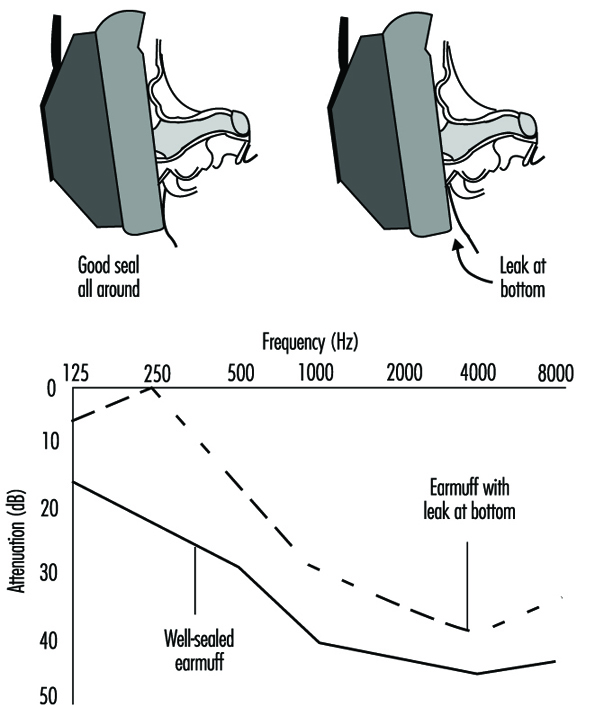
Earplugs
Figure 4 displays an example of a well-fitted, fully inserted foam earplug (about 60% of it extends into the ear canal) and an example of a poorly fitted, shallowly inserted foam earplug that just caps the ear canal entrance. The well-fitted earplug has good attenuation at all frequencies. The poorly fitted foam earplug has substantially less attenuation. The foam earplug, when fitted properly, can provide attenuation approaching bone conduction at many frequencies. In high-level noise, the differences in attenuation between a well-fitted and a poorly fitted foam earplug can be sufficient to either prevent or permit noise-induced hearing loss.
Figure 4. A well-fitted and a poorly fitted foam earplug and the attenuation consequences
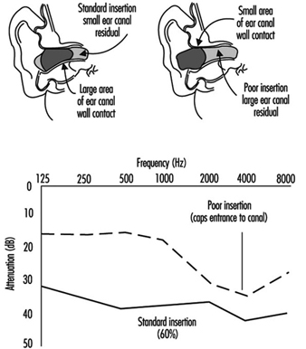
Figure 5 displays a well-fitted and poorly fitted premolded earplug. In general, premolded earplugs do not provide the same degree of attenuation as properly fitted foam earplugs or earmuffs. However, the well-fitted premolded earplug provides adequate attenuation for most industrial noises. The poorly fitted premolded earplug provides substantially less, and no attenuation at 250 and 500 Hz. It has been observed that for some wearers, there is actually gain at these frequencies, meaning that the protected noise level is actually higher than the environmental noise level, putting the wearer at more risk of developing noise-induced hearing loss than if the protector were not worn at all.
Figure 5. A well-fitted and a poorly fitted premolded earplug
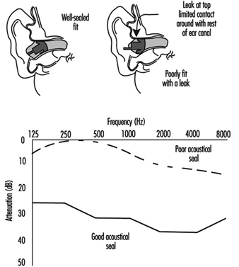
Dual hearing protection
For some environmental noises, especially when daily equivalent exposures exceed about 105 dBA, a single hearing protector may be insufficient. In such situations wearers can use both earmuffs and earplugs in combination to achieve about 3 to 10 dB of extra protection, limited primarily by the bone conduction of the head of the wearer. Attenuation changes very little when different earmuffs are used with the same earplug, but changes greatly when different earplugs are used with the same earmuff. For dual protection, the choice of the earplug is critical for attenuation below 2,000 Hz, but at and above 2,000 Hz essentially all earmuff/earplug combinations provide attenuation approximately equal to the skull’s bone-conduction pathways.
Interference from glasses and head-worn personal protective equipment
Safety glasses, or other devices such as respirators that interfere with the earmuff’s circumaural seal, can degrade earmuff attenuation. For example, eye wear can reduce attenuation in individual octave bands by 3 to 7 dB.
Flat-response devices
A flat-attenuation earmuff or earplug is one that provides approximately equal attenuation for frequencies from 100 to 8,000 Hz. These devices maintain the same frequency response as the unoccluded ear, providing undistorted audition of signals (Berger 1991). A normal earmuff or earplug may sound as if the treble of the signal has been turned down, in addition to the overall lowering of the sound level. The flat-attenuation earmuff or earplug will sound as if only the volume has been reduced since its attenuation characteristics are “tuned” by the use of resonators, dampers and diaphragms. Flat-attenuation characteristics can be important for wearers having high-frequency hearing loss, for those for whom understanding speech while being protected is important, or for those for whom having high-quality sound is important, such as musicians. Flat attenuation devices are available as earmuffs and earplugs. One drawback of the flat-attenuation devices is that they don’t provide as much attenuation as conventional earmuffs and earplugs.
Passive amplitude-sensitive devices
A passive amplitude-sensitive hearing protector has no electronics and is designed to allow voice communications during quiet periods and provide little attenuation at low noise levels with protection increasing as the noise level increases. These devices contain orifices, valves, or diaphragms intended to produce this nonlinear attenuation, typically beginning once sound levels exceed 120 dB sound pressure levels (SPL). At sound levels below 120 dB SPL, orifice and valve-type devices typically act as vented earmolds, providing as much as 25 dB of attenuation at the higher frequencies, but very little attenuation at and below 1,000 Hz. Few occupational and recreational activities, other than shooting competitions (especially in outdoor environments), are appropriate if this type of hearing protector is expected to be truly effective in preventing noise-induced hearing loss.
Active amplitude-sensitive devices
An active amplitude-sensitive hearing protector has electronics and design goals similar to a passive amplitude-sensitive protector. These systems employ a microphone placed on the exterior of the ear cup or ported to the lateral surface of the earplug. The electronic circuit is designed to provide less and less amplification, or in some cases to completely shut down, as the environmental noise level increases. At the levels of normal conversational speech, these devices provide unity gain, (the loudness of speech is the same as if the protector wasn’t worn), or even a small amount of amplification. The goal is to keep the sound level under the earmuff or earplug to less than a 85 dBA diffuse-field equivalent. Some of the units built into earmuffs have a channel for each ear, thus allowing some level of localization to be maintained. Others have only one microphone. The fidelity (naturalness) of these systems varies among manufacturers. Because of the electronics package built into the ear cup which is necessary to have an active level-dependent system, these devices provide about four to six decibels less attenuation in their passive state, electronics turned off, than similar earmuffs without the electronics.
Active noise reduction
Active noise reduction, while an old concept, is a relatively new development for hearing protectors. Some units work by capturing the sound inside the ear cup, inverting its phase, and retransmitting the inverted noise into the ear cup to cancel the incoming sound. Other units work by capturing sound outside the ear cup, modifying its spectrum to account for the attenuation of the ear cup, and inserting the inverted noise into the ear cup, effectively using the electronics as a timing device so that the electrically inverted sound arrives in the ear cup at the same time as the noise transmitted through the ear cup. Active noise reduction is limited to the reduction of low-frequency noises below 1,000 Hz, with a maximum attenuation of 20 to 25 dB occurring at or below 300 Hz.
However, a portion of the attenuation provided by the active noise reduction system simply offsets the reduction in attenuation of the earmuffs that is caused by the inclusion in the ear cup of the very electronics which are required to effect the active noise reductions. At present these devices cost 10 to 50 times that of passive earmuffs or earplugs. If the electronics fail, the wearer may be inadequately protected and could experience more noise under the ear cup than if the electronics were simply shut off. As active noise cancellation devices become more popular, costs should diminish and their applicability may become more widespread.
The Best Hearing Protector
The best hearing protector is the one that the wearer will use willingly, 100% of the time. It is estimated that approximately 90% of noise-exposed workers in the manufacturing sector in the United States are exposed to noise levels of less than 95 dBA (Franks 1988). They need between 13 and 15 dB of attenuation to provide them with adequate protection. There are a wide array of hearing protectors that can provide sufficient attenuation. Finding the one that each worker will wear willingly 100% of the time is the challenge.
Head Protection
Head Injuries
Head injuries are fairly common in industry and account for 3 to 6% of all industrial injuries in industrialized countries. They are often severe and result in an average lost time of about three weeks. The injuries sustained are generally the result of blows caused by the impact of angular objects such as tools or bolts falling from a height of several metres; in other cases, workers may strike their heads in a fall to a floor or suffer a collision between some fixed object and their heads.
A number of different types of injury have been recorded:
- perforation of the skull resulting from the application of an excessive force to a very localized area, as for example in the case of direct contact with a pointed or sharp-edged object
- fracture of the skull or of the cervical vertebrae occurring when an excessive force is applied on a larger area, stressing the skull beyond the limits of its elasticity or compressing the cervical portion of the spine
- brain lesions without fracture of the skull resulting from the brain being displaced suddenly within the skull, which may lead to contusion, concussion, haemorrhage of the brain or circulatory problems.
Understanding the physical parameters that account for these various types of injury is difficult, although of fundamental importance, and there is considerable disagreement in the extensive literature published on this subject. Some specialists consider that the force involved is the principal factor to be considered, while others claim that it is a matter of energy, or of the quantity of movement; further opinions relate the brain injury to acceleration, to acceleration rate, or to a specific shock index such as HIC, GSI, WSTC. In most cases, each one of these factors is likely to be involved to a greater or lesser extent. It may be concluded that our knowledge of the mechanisms of shocks to the head is still only partial and controversial. The shock tolerance of the head is determined by means of experimentation on cadavers or on animals, and it is not easy to extrapolate these values to a living human subject.
On the basis of the results of analyses of accidents sustained by building workers wearing safety helmets, however, it seems that head injuries due to shocks occur when the quantity of energy involved in the shock is in excess of about 100 J.
Other types of injuries are less frequent but should not be overlooked. They include burns resulting from splashes of hot or corrosive liquids or molten material, or electrical shocks resulting from accidental contact of the head with exposed conductive parts.
Safety Helmets
The chief purpose of a safety helmet is to protect the head of the wearer against hazards, mechanical shocks. It may in addition provide protection against other for example, mechanical, thermal and electrical.
A safety helmet should fulfil the following requirements in order to reduce the harmful effects of shocks to the head:
- It should limit the pressure applied to the skull by spreading the load over the largest possible surface. This is achieved by providing a sufficiently large harness that closely match various skull shapes, together with a hard shell strong enough to prevent the head from coming into direct contact with accidentally falling objects and to provide protection if the wearer’s head should hit a hard surface (figure 1). The shell must therefore resist deformation and perforation.
- It should deflect falling objects by having a suitably smooth and rounded shape. A helmet with protruding ridges tends to arrest falling objects rather than to deflect them and thus retain slightly more kinetic energy than helmets which are perfectly smooth.
- It should dissipate and disperse the energy that may be transmitted to it in such a way that the energy is not passed totally to the head and neck. This is achieved by means of the harness, which must be securely fixed to the hard shell so that it can absorb a shock without being detached from the shell. The harness must also be flexible enough to undergo deformation under impact without touching the inside surface of the shell. This deformation, which absorbs most of the energy of a shock, is limited by the minimum amount of clearance between the hard shell and the skull and by the maximum elongation of the harness before it breaks. Thus the rigidity or stiffness of the harness should be the result of a compromise between the maximum amount of energy that it is designed to absorb and the progressive rate at which the shock is to be allowed to be transmitted to the head.
Figure 1. Example of essential elements of safety helmet construction
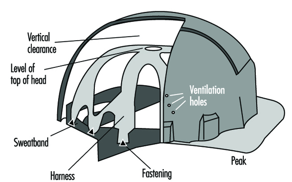 Other requirements may apply to helmets used for particular tasks. These include protection against splashes of molten metal in the iron and steel industry and protection against electrical shock by direct contact in the case of helmets used by electrical technicians.
Materials used in the manufacture of helmets and harnesses should retain their protective qualities over a long period of time and under all foreseeable climatic conditions, including sun, rain, heat, bela-freezing temperature, and so on. Helmets should also have a fairly good resistance to flame and should not break if dropped onto a hard surface from a height of a few metres.
Performance Tests
ISO International Standard No. 3873-1977 was published in 1977 as a result of the work of the subcommittee dealing especially with “industrial safety helmets”. This standard, approved by practically all the member states of the ISO, sets out the essential features required of a safety helmet together with the related testing methods. These tests may be divided into two groups (see table 1), namely:
- obligatory tests, to be applied to all types of helmets for whatever use they may be intended: shock-absorbing capacity, resistance to perforation and resistance to flame
- optional tests, intended to be applied to safety helmets designed for special groups of users: dielectric strength, resistance to lateral deformation and resistance to low temperature.
Table 1. Safety helmets: testing requirements of ISO Standard 3873-1977
|
Characteristic |
Description |
Criteria |
|
Obligatory tests |
||
|
Absorption of shocks |
A hemispherical mass of 5 kg is allowed to fall from a height of |
The maximum force measured should not exceed 500 daN. |
|
The test is repeated on a helmet at temperatures of –10°, +50°C and under wet conditions., |
||
|
Resistance to penetration |
The helmet is struck within a zone of 100 mm in diameter on its uppermost point using a conical punch weighing 3 kg and a tip angle of 60°. |
The tip of the punch must not come into contact with the false (dummy) head. |
|
Test to be performed under the conditions which gave the worst results in the shock test., |
||
|
Resistance to flame |
The helmet is exposed for 10 s to a Bunsen burner flame of 10 mm in diameter using propane. |
The outer shell should not continue to burn more than 5 s after it has been withdrawn from the flame. |
|
Optional tests |
||
|
Dielectric strength |
The helmet is filled with a solution of NaCl and is itself immersed in a bath of the same solution. The electric leakage under an applied voltage of 1200 V, 50 Hz is measured. |
The leakage current should not be greater than 1.2 mA. |
|
Lateral rigidity |
The helmet is placed sideways between two parallel plates and subjected to a compressive pressure of 430 N |
The deformation under load should not exceed 40 mm, and the permanent deformation should not be more than 15 mm. |
|
Low-temperature test |
The helmet is subject to the shock and penetration tests at a temperature of -20°C. |
The helmet must fulfil the foregoing requirements for these two tests. |
The resistance to ageing of the plastic materials used in the manufacture of helmets is not specified in ISO No. 3873-1977. Such a specification should be required for helmets made out of plastic materials. A simple test consists in exposing the helmets to a high-pressure, quartz-envelope 450 watt xenon lamp over a period of 400 hours at a distance of 15 cm, followed by a check to ensure that the helmet can still withstand the appropriate penetration test.
It is recommended that helmets intended for use in the iron and steel industry be subjected to a test for resistance to splashes of molten metal. A quick way of carrying out this test is to allow 300 grams of molten metal at 1,300°C to drop onto the top of a helmet and to check that none has passed through to the interior.
The European Standard EN 397 adopted in 1995 specifies requirements and test methods for these two important characteristics.
Selection of a Safety Helmet
The ideal helmet providing protection and perfect comfort in every situation has yet to be designed. Protection and comfort are indeed often conflicting requirements. As regards protection, in selecting a helmet, the hazards against which protection is required and the conditions under which the helmet will be used must be considered with specific attention to the characteristics of the available safety products.
General considerations
It is advisable to choose helmets complying with the recommendations of ISO Standard No. 3873 (or its equivalent). The European Standard EN 397-1993 is used as a reference for the certification of helmets in application of the 89/686/EEC directive: equipment undergoing such certification, as is the case with almost all personal protective equipment, is submitted to a mandatory third party certification before being put onto the European market. In any case, helmets should meet the following requirements:
- A good safety helmet for general use should have a strong shell able to resist deformation or puncture (in the case of plastics, the shell wall should be not less than 2 mm in thickness), a harness fixed in such a way as to ensure that there is always a minimum clearance of 40 to 50 mm between its upper side and the shell, and an adjustable headband fitted to the cradle to ensure a close and stable fit (see figure 1).
- The best protection against perforation is provided by helmets made of thermoplastic materials (polycarbonates, ABS, polyethylene and polycarbonate–glass fibre) and fitted with a good harness. Helmets made of light metal alloys do not stand up well to puncture by pointed or sharp-edged objects.
- Helmets with protruding parts inside the shell should not be used, as these may cause serious injuries in the case of a sideways blow; they should be fitted with a lateral protective padding that must be neither flammable nor subject to melting under the effect of heat. A padding made of fairly rigid and flame resistant foam, 10 to 15 mm thick and at least 4 cm wide will serve this purpose.
- Helmets made of polyethylene, polypropylene or ABS tend to lose their mechanical strength under the effects of heat, cold and particularly heavy exposure to sunlight or ultraviolet (UV) radiation. If such helmets are regularly used in the open air or near UV sources like welding stations, they should be replaced at least every three years. Under such conditions, it is recommended that polycarbonate, polyester or polycarbonate–glass fibre helmets be used, as these have a better resistance to ageing. In any case, any evidence of discoloration, cracks, shredding of fibres or of creaking when the helmet is twisted, should cause the helmet to be discarded.
- Any helmet that has been submitted to a heavy blow, even if there are no evident signs of damage, should be discarded.
Special considerations
Helmets made of light alloys or having a brim along the sides should not be used in workplaces where there is a hazard of molten metal splashes. In such cases, the use of polyester–glass fibre, phenol textile, polycarbonate–glass fibre or polycarbonate helmets is recommended.
Where there is a hazard of contact with exposed conductive parts, only helmets made of thermoplastic material should be used. They should not have ventilation holes and no metal parts such as rivets should appear on the outside of the shell.
Helmets for persons working overhead, particularly steel framework erectors, should be provided with chin straps. The straps should be about 20 mm in width and should be such that the helmet is held firmly in place at all times.
Helmets made largely of polyethene are not recommended for use at high temperatures. In such cases, polycarbonate, polycarbonate–glass fibre, phenol textile, or polyester–glass fibre helmets are more suitable. The harness should be made of woven fabric. Where there is no hazard of contact with exposed conductive parts, ventilation holes in the helmet shell may be provided.
Situations where there is a crushing hazard call for helmets made of glass–fibre reinforced polyester or polycarbonate having a rim with a width of not less than 15 mm.
Comfort considerations
In addition to safety, consideration should also be given to the physiological aspects of comfort for the wearer.
The helmet should be as light as possible, certainly not more than 400 grams in weight. Its harness should be flexible and permeable to liquid and should not irritate or injure the wearer; for this reason, harnesses of woven fabric are to be preferred to those made of polyethene. A full or half leather sweatband should be incorporated not only in order to provide sweat absorption but also to reduce skin irritation; it should be replaced several times during the life of the helmet for hygienic reasons. To ensure better thermal comfort, the shell should be of a light colour and have ventilation holes with a surface range of 150 to 450 mm2. Careful adjustment of the helmet to fit the wearer is necessary in order to ensure its stability and to prevent its slipping and reducing the field of vision. Various helmet shapes are available, the most common being the “cap” shape with a peak and a brim around the sides; for work in quarries and on demolition sites, the “hat” type of helmet with a wider brim provides better protection. A “skull-cap” shaped helmet without a peak or a brim is particularly suitable for persons working overhead as this pattern precludes a possible loss of balance caused by the peak or brim coming into contact with joists or girders among which the worker may have to move.
Accessories and Other Protective Headgear
Helmets may be fitted with eye or face shields made of plastic material, metallic mesh or optical filters; hearing protectors, chin straps and nape straps to keep the helmet firmly in position; and woollen neck protectors or hoods against wind or cold (figure 2). For use in mines and underground quarries, attachments for a headlamp and a cable holder are fitted.
Figure 2. Example of safety helmet with chin strap (a), optical filter (b) and woolen neck protector against wind and cold (c)
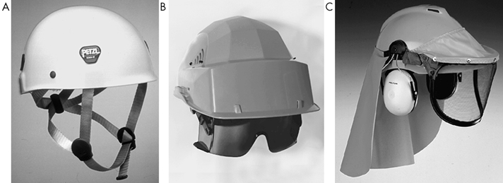
Other types of protective headgear include those designed for protection against dirt, dust, scratches and bumps. Sometimes known as “bump caps,” these are made of light plastic material or linen. For persons working near machine tools such as drills, lathes, spooling machines and so forth, where there is a risk of the hair being caught, linen caps with a net, peaked hair nets or even scarves or turbans may be used, provided that they have no exposed loose ends.
Hygiene and Maintenance
All protective headgear should be cleaned and checked regularly. If splits or cracks appear, or if a helmet shows signs of ageing or deterioration of the harness, the helmet should be discarded. Cleaning and disinfection are particularly important if the wearer sweats excessively or if more than one person share the same headgear.
Substances adhering to a helmet such as chalk, cement, glue or resin may be removed mechanically or by using an appropriate solvent that does not attack the shell material. Warm water with a detergent may be used with a hard brush.
For disinfecting headgear, articles should be dipped into a suitable disinfecting solution such as a 5% formalin solution or a sodium hypochlorite solution.
Foot and Leg Protection
Injuries to the foot and leg are common to many industries. The dropping of a heavy object may injure the foot, particularly the toes, in any workplace, especially among workers in the heavier industries such as mining, metal manufacture, engineering and building and construction work. Burns of the lower limbs from the molten metals, sparks or corrosive chemicals occur frequently in foundries, iron- and steelworks, chemical plants and so on. Dermatitis or eczema may be caused by a variety of acidic, alkaline and many other agents. The foot may also suffer physical injury caused by striking it against an object or by stepping on sharp protrusions such as can occur in the construction industry.
Improvements in the work environment have made the simple puncturing and laceration of the worker’s foot by protruding floor nails and other sharp hazards less common, but accidents from working on damp or wet floors still occur, particularly when wearing unsuitable foot wear.
Types of Protection.
The type of foot and leg protection should be related to the risk. In some light industries, it may be sufficient hat workers wear well-made ordinary shoes. Many women, for example will wear footwear that is comfortable to them, such as sandals or old slippers, or footwear with very high or worn-down heels. This practice should be discouraged because such footwear can cause an accident.
Sometimes a protective shoe or clog is adequate, and sometimes a boot or leggings will be required (see figure 1, figure 2 and figure 3). The height to which the footwear covers the ankle, knee or thigh depends on the hazard, although comfort and mobility will also have to be considered. Thus shoes and gaiters may in some circumstances be preferable to high boots.
Figure 1. Safety shoes
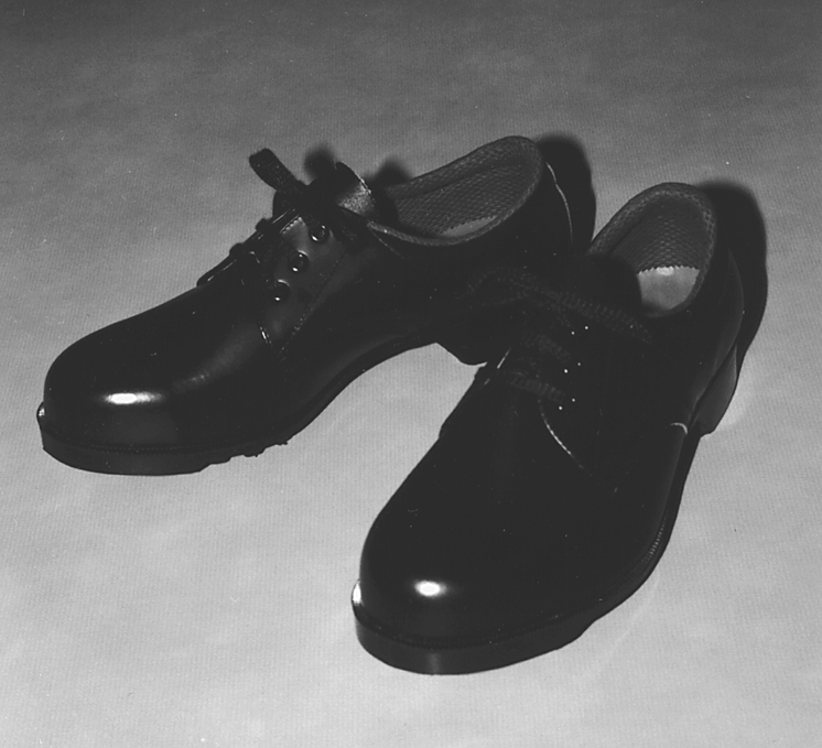
Figure 2. Heat protective boots
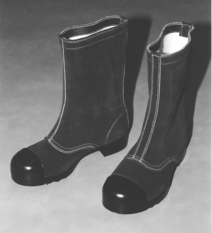
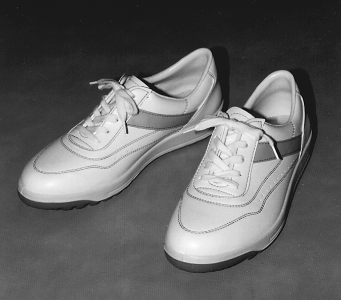
Protective shoes and boots may be made from leather, rubber, synthetic rubber or plastic and may be fabricated by sewing, vulcanizing or moulding. Since the toes are most vulnerable to impact injuries, a steel toe cap is the essential feature of protective footwear wherever such hazards exist. For comfort the toe cap must be reasonably thin and light, and carbon tool steel is therefore used for this purpose. These safety toe caps may be incorporated into many types of boots and shoes. In some trades where falling objects present a particular risk, metal instep guards may be fitted over protective shoes.
Rubber or synthetic outer soles with various tread patterns are used to minimize or prevent the risk of slipping: this is especially important where floors are likely to be wet or slippery. The material of the sole appears to be of more importance than the tread pattern and should have a high coefficient of friction. Reinforced, puncture-proof soles are necessary in such places as construction sites; metallic insoles can also be inserted into various types of footwear that lack this protection.
Where an electrical hazard exists, shoes should be either entirely stitched or cemented, or directly vulcanized in order to avoid the need for nails or any other electrically conductive fasteners. Where static electricity may be present, protective shoes should have electrically conductive rubber outer soles to allow static electricity to leak from the bottom of the shoes.
Footwear with a dual purpose has now come into common use: these are shoes or boots that have both anti-electrostatic properties mentioned above together with the ability to protect the wearer from receiving an electrical shock when in contact with a low-voltage electrical source. In the latter case, the electrical resistance between the insole and the outer sole must be controlled in order to provide this protection between a given voltage range.
In the past, “safety and durability” were the only considerations. Now, worker comfort has also been taken into account, so that lightness, comfort and even attractiveness in protective shoes are sought-after qualities. The “safety sneaker” is one example of this kind of footwear. Design and colour may come to play a part in the use of footwear as an emblem of corporate identity, a matter that receives special attention in countries like Japan, to name only one.
Synthetic rubber boots offer useful protection from chemical injuries: the material should show not more than 10% reduction in tensile strength or elongation after immersion in a 20% solution of hydrochloric acid for 48 hours at room temperature.
Especially in environments where molten metals or chemical burns are a major hazard, it is important that shoes or boots should be without tongues and that the fastenings should be pulled over the top of the boot and not tucked inside.
Rubber or metallic spats, gaiters or leggings may be used to protect the leg above the shoe line, especially from risks of burns. Protective knee pads may be necessary, especially where work involves kneeling, for example in some foundry moulding. Aluminized heat-protective shoes, boots or leggings will be necessary near sources of intense heat.
Use and Maintenance
All protective footwear should be kept clean and dry when not in use and should be replaced as soon as necessary. In places where the same rubber boots are used by several people, regular arrangements for disinfection between each use should be made to prevent the spread of foot infections. A danger of foot mycosis exists that arises from the use of too tight and too heavy types of boots or shoes.
The success of any protective footwear depends upon its acceptability, a reality that is now widely recognized in the far greater attention that is now paid to styling. Comfort is a prerequisite and the shoes should be as light as is consistent with their purpose: shoes weighing more than two kilogram per pair should be avoided.
Sometimes foot and leg safety protection is required by law to be provided by the employers. Where the employers are interested in progressive programmes and not just meeting legal obligations, concerned companies often find it very effective to provide some arrangement for easy purchase at the place of work. And if protective wear can be offered at wholesale price, or arrangements for convenient extended payment terms are made available, workers may be more willing and able to purchase and use better equipment. In this way, the type of protection obtained and worn can be better controlled. Many conventions and regulations, however, do consider supplying workers with work clothing and protective equipment to be the employer’s obligation.
Eye and Face Protections
Eye and face protection includes safety spectacles, goggles, face shields and similar items used to protect against flying particles and foreign bodies, corrosive chemicals, fumes, lasers and radiation. Often, the whole face may need protection against radiation or mechanical, thermal or chemical hazards. Sometimes a face shield may be adequate also for protecting the eyes, but often specific eye protection is necessary, either separately or as a complement to the face protection.
A wide range of occupations require eye and face protectors: hazards include flying particles, fumes or corrosive solids, liquids or vapours in polishing, grinding, cutting, blasting, crushing, galvanizing or various chemical operations; against intensive light as in laser operations; and against ultraviolet or infrared radiation in welding or furnace operations. Of the many types of eye and face protection available, there is a correct type for each hazard. Whole-face protection is preferred for certain severe risks. As needed, hood or helmet type face protectors and face shields are used. Spectacles or goggles may be used for specific eye protection.
The two basic problems in wearing eye and face protectors are (1) how to provide effective protection which is acceptable for wearing over long hours of work without undue discomfort, and (2) the unpopularity of eye and face protection due to restriction of vision. The wearer’s peripheral vision is limited by the side frames; the nose bridge may disturb binocular vision; and misting is a constant problem. Particularly in hot climates or in hot work, additional coverings of the face may become intolerable and may be discarded. Short-term, intermittent operations also create problems as workers may be forgetful and disinclined to use protection. First consideration should always be given to the improvement of the working environment rather than to the possible need for personal protection. Before or in conjunction with the use of eye and face protection, consideration must be given to guarding of machines and tools (including interlocking guards), removal of fumes and dust by exhaust ventilation, screening of sources of heat or radiation, and screening of points from which particles may be ejected, such as abrasive grinders or lathes. When the eyes and face can be protected by the use of transparent screens or partitions of appropriate size and quality, for example, these alternatives are to be preferred to the use of personal eye protection.
There are six basic types of eye and face protection:
- spectacle type, either with or without side shields (figure 1)
- eye cup (goggle) type (figure 2)
- face shield type, covering eye sockets and the central portion of the face (figure 3)
- helmet type with shielding of the whole front of the face (figure 4)
- hand-held shield type (see figure 4)
- hood type, including the diver’s helmet type covering the head completely (see figure 4)
Figure 1. Common types of spectacles for eye protection with or without sideshield
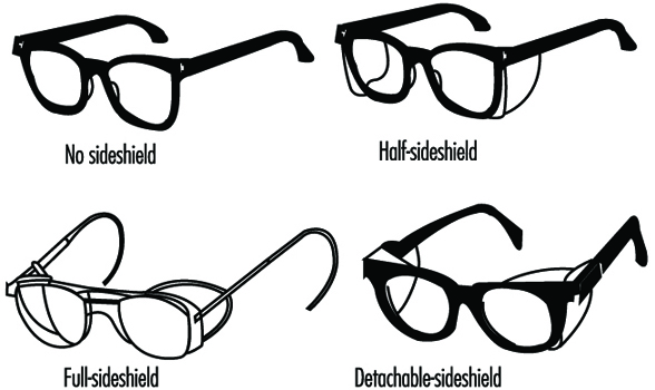
Figure 2. Examples of goggle-type eye protectors
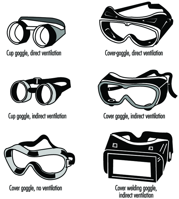 .
.
Figure 3. Face shield type protectors for hot work
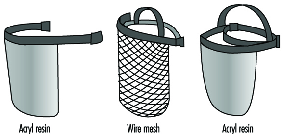
Figure 4. Protectors for welders
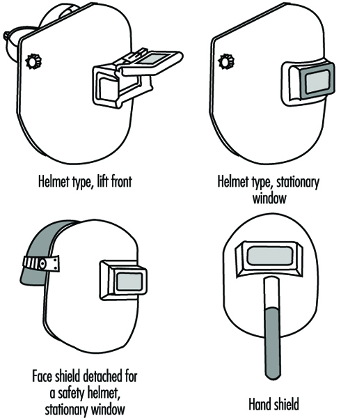
There are goggles that may be worn over corrective spectacles. It is often better for the hardened lenses of such goggles to be fitted under the guidance of an ophthalmic specialist.
Protection against Specific Hazards
Traumatic and chemical injuries. Face shields or eye protectors are used against flying
particles, fumes, dust and chemical hazards. Common types are spectacles (often with side shields), goggles, plastic eye shields and face shields. The helmet type is used when injury risks are expected from various directions. The hood type and the diver’s helmet type are used in sand- and shot-blasting. Transparent plastics of various sorts, hardened glass or a wire screen may be used for protection against certain foreign bodies. Eye cup goggles with plastic or glass lenses or plastic eye shields as well as a diver’s helmet type shield or face shields made of plastic are used for protection against chemicals.
Materials commonly used include polycarbonates, acrylic resins or fibre-based plastics. Polycarbonates are effective against impacts but may not be suitable against corrosives. Acrylic protectors are weaker against impacts but suitable for protection from chemical hazards. Fibre-based plastics have the advantage of adding anti-misting coating. This anti-misting coating also prevents electrostatic effects. Thus such plastic protectors may be used not only in physically light work or chemical handling but also in modern clean-room work.
Thermal radiation. Face shields or eye protectors against infrared radiation are used mainly in furnace operations and other hot work involving exposure to high-temperature radiation sources. Protection is usually necessary at the same time against sparks or flying hot objects. Face protectors of the helmet type and the face shield type are mainly used. Various materials are used, including metal wire meshes, punched aluminium plates or similar metal plates, aluminized plastic shields or plastic shields with gold layer coatings. A face shield made of wire mesh can reduce thermal radiation by 30 to 50%. Aluminized plastic shields give good protection from radiant heat. Some examples of face shields against thermal radiation are given in figure 1.
Welding. Goggles, helmets or shields that give maximum eye protection for each welding and cutting process should be worn by operators, welders and their helpers. Effective protection is needed not only against intensive light and radiation but also against impacts upon the face, head and neck. Fibreglass-reinforced plastic or nylon protectors are effective but rather expensive. Vulcanized fibres are commonly used as shield material. As shown in figure 4, both helmet type protectors and hand-held shields are used to protect the eyes and face at the same time. Requirements for correct filter lenses to be used in various welding and cutting operations are described below.
Wide spectral bands. Welding and cutting processes or furnaces emit radiations in the ultraviolet, visible and infrared bands of the spectrum, which are all able to produce harmful effects upon the eyes. Spectacle type or goggle type protectors similar to those shown in figure 1 and figure 2 as well as welders’ protectors such as those shown in figure 4 can be used. In welding operations, helmet type protection and hand-shield type protectors are generally used, sometimes in conjunction with spectacles or goggles. It should be noted that protection is necessary also for the welder’s assistant.
Transmittance and tolerances in transmittance of various shades of filter lenses and filter plates of eye protection against high-intensity light are shown in table 1. Guides for selecting correct filter lenses in terms of the scales of protection are given in table 2 through table 6).
Table 1. Transmittance requirements (ISO 4850-1979)
|
Scale number |
Maximum transmittance in the ultraviolet spectrum t ( |
Luminous transmittance ( |
Maximum mean transmittance in the infrared spectrum , % |
|||
|
|
313 nm |
365 nm |
maximum |
minimum |
Near IR 1,300 to 780 nm, |
Mid. IR 2,000 to 1,300 nm , |
|
1.2 1.4 1.7 2.0 2.5 3 4 5 6 7 8 9 10 11 12 13 14 15 16 |
0,0003 0,0003 0,0003 0,0003 0,0003 0,0003 0,0003 0,0003 0,0003 0,0003 0,0003 0,0003 0,0003 Value less than or equal to transmittance permitted for 365 nm |
50 35 22 14 6,4 2,8 0,95 0,30 0,10 0,037 0,013 0,0045 0,0016 0,00060 0,00020 0,000076 0,000027 0,0000094 0,0000034 |
100 74,4 58,1 43,2 29,1 17,8 8,5 3,2 1,2 0,44 0,16 0,061 0,023 0,0085 0,0032 0,0012 0,00044 0,00016 0,000061 |
74,4 58,1 43,2 29,1 17,8 8,5 3,2 1,2 0,44 0,16 0,061 0,023 0,0085 0,0032 0,0012 0,00044 0,00016 0,000061 0,000029 |
37 33 26 21 15 12 6,4 3,2 1,7 0,81 0,43 0,20 0,10 0,050 0,027 0,014 0,007 0,003 0,003 |
37 33 26 13 9,6 8,5 5,4 3,2 1,9 1,2 0,68 0,39 0,25 0,15 0,096 0,060 0,04 0,02 0,02 |
Taken from ISO 4850:1979 and reproduced with the permission of the International Organization for Standardization (ISO). These standards can be obtained from any ISO member or from the ISO Central Secretariat, Case postale 56, 1211 Geneva 20, Switzerland. Copyright remains with ISO.
Table 2. Scales of protection to be used for gas-welding and braze-welding
|
Work to be carried out1 |
l = flow rate of acetylene, in litres per hour |
|||
|
l £ 70 |
70 l £ 200 |
200 l £ 800 |
l > 800 |
|
|
Welding and braze-welding |
4 |
5 |
6 |
7 |
|
Welding with emittive |
4a |
5a |
6a |
7a |
1 According to the conditions of use, the next greater or the next smaller scale can be used.
Taken from ISO 4850:1979 and reproduced with the permission of the International Organization for Standardization (ISO). These standards can be obtained from any ISO member or from the ISO Central Secretariat, Case postale 56, 1211 Geneva 20, Switzerland. Copyright remains with ISO.
Table 3. Scales of protection to be used for oxygen cutting
|
Work to be carried out1 |
Flow rate of oxygen, in litres per hour |
||
|
900 to 2,000 |
2,000 to 4,000 |
4,000 to 8,000 |
|
|
Oxygen cutting |
5 |
6 |
7 |
1 According to the conditions of use, the next greater or the next smaller scale can be used.
NOTE: 900 to 2,000 and 2,000 to 8,000 litres of oxygen per hour, correspond fairly closely to the use of cutting nozzles diameters of 1 to 1.5 and 2 mm respectively.
Taken from ISO 4850:1979 and reproduced with the permission of the International Organization for Standardization (ISO). These standards can be obtained from any ISO member or from the ISO Central Secretariat, Case postale 56, 1211 Geneva 20, Switzerland. Copyright remains with ISO.
Table 4. Scales of protection to be used for plasma arc cutting
|
Work to be carried out1 |
l = Current, in amperes |
||
|
l £ 150 |
150 l £ 250 |
250 l £ 400 |
|
|
Thermal cutting |
11 |
12 |
13 |
1 According to the conditions of use, the next greater or the next smaller scale can be used.
Taken from ISO 4850:1979 and reproduced with the permission of the International Organization for Standardization (ISO). These standards can be obtained from any ISO member or from the ISO Central Secretariat, Case postale 56, 1211 Geneva 20, Switzerland. Copyright remains with ISO.
Table 5. Scales of protection to be used for electric arc welding or gouging

1 According to the conditions of use, the next greater or the next smaller scale can be used.
2 The expression “heavy metals” applies to steels, alloy stells, copper and its alloys, etc.
NOTE: The coloured areas correspond to the ranges where the welding operations are not usually used in the current practice of manual welding.
Taken from ISO 4850:1979 and reproduced with the permission of the International Organization for Standardization (ISO). These standards can be obtained from any ISO member or from the ISO Central Secretariat, Case postale 56, 1211 Geneva 20, Switzerland. Copyright remains with ISO.
Table 6. Scales of protection to be used for plasma direct arc welding

1 According to the conditions of use, the next greater or the next smaller scale can be used.
The coloured areas correspond to the ranges where the welding operations are not usually used in the current practice of manual welding.
Taken from ISO 4850:1979 and reproduced with the permission of the International Organization for Standardization (ISO). These standards can be obtained from any ISO member or from the ISO Central Secretariat, Case postale 56, 1211 Geneva 20, Switzerland. Copyright remains with ISO.
A new development is the use of filter plates made of welded crystal surfaces which increase their protective shade as soon as the welding arc starts. The time for this nearly instantaneous shade increase can be as short as 0.1 ms. The good visibility through the plates in non-welding situations can encourage their use.
Laser beams. No one type of filter offers protection from all laser wavelengths. Different kinds of lasers vary in wavelength, and there are lasers that produce beams of various wavelengths or those whose beams change their wavelengths by passing through optical systems. Consequently, laser-using firms should not depend solely on laser protectors to protect an employee’s eyes from laser burns. Nevertheless, laser operators do frequently need eye protection. Both spectacles and goggles are available; they have shapes similar to those shown in figure 1 and figure 2. Each kind of eyewear has maximum attenuation at a specific laser wavelength. Protection falls off rapidly at other wavelengths. It is essential to select the correct eyewear appropriate for the kind of laser, its wavelength and optical density. The eyewear is to provide protection from reflections and scattered lights and the utmost precautions are necessary to foresee and avoid harmful radiation exposure.
With the use of eye and face protectors, due attention must be paid to greater comfort and efficiency. It is important that the protectors be fitted and adjusted by a person who has received some training in this task. Each worker should have the exclusive use of his or her own protector, while communal provision for cleaning and demisting may well be made in larger works. Comfort is particularly important in helmet and hood type protectors as they may become almost intolerably hot during use. Air lines can be fitted to prevent this. Where the risks of the work process allow, some personal choice among different types of protection is psychologically desirable.
The protectors should be examined regularly to ensure that they are in good condition. Care should be taken that they give adequate protection at all times even with the use of corrective vision devices.
Overview and Philosophy of Personal Protection
The entire topic of personal protection must be considered in the context of control methods for preventing occupational injuries and diseases. This article presents a detailed technical discussion of the types of personal protection which are available, the hazards for which their use may be indicated and the criteria for selecting appropriate protective equipment. Where they are applicable, the approvals, certifications and standards which exist for protective devices and equipment are summarized. In using this information, it is essential to be constantly mindful that personal protection should be considered the method of last resort in reducing the risks found in the workplace. In the hierarchy of methods which may be used to control workplace hazards, personal protection is not the method of first choice. In fact, it is to be used only when the possible engineering controls which reduce the hazard (by methods such as isolation, enclosure, ventilation, substitution, or other process changes), and administrative controls (such as reducing work time at risk for exposure) have been implemented to the extent feasible. There are cases, however, where personal protection is necessary, whether as a short-term or a long-term control, to reduce occupational disease and injury risks. When such use is necessary, personal protective equipment and devices must be used as part of a comprehensive programme which includes full evaluation of the hazards, correct selection and fitting of the equipment, training and education for the people who use the equipment, maintenance and repair to keep the equipment in good working order and overall management and worker commitment to the success of the protection programme.
Elements of a Personal Protection Programme
The apparent simplicity of some personal protective equipment can result in a gross underestimation of the amount of effort and expense required to effectively use this equipment. While some devices are relatively simple, such as gloves and protective footwear, other equipment such as respirators can actually be very complex. The factors which make effective personal protection difficult to achieve are inherent in any method which relies upon modification of human behaviour to reduce risk, rather than on protection which is built into the process at the source of the hazard. Regardless of the particular type of protective equipment being considered, there is a set of elements which must be included in a personal protection programme.
Hazard evaluation
If personal protection is to be an effective answer to a problem of occupational risk, the nature of the risk itself and its relationship to the overall work environment must be fully understood. While this may seem so obvious that it barely needs to be mentioned, the apparent simplicity of many protective devices can present a strong temptation to short cut this evaluation step. The consequences of providing protective devices and equipment which are not suitable to the hazards and the overall work environment range from reluctance or refusal to wear inappropriate equipment, to impaired job performance, to risk of worker injury and death. In order to achieve a proper match between the risk and the protective measure, it is necessary to know the composition and magnitude (concentration) of the hazards (including chemical, physical or biological agents), the length of time for which the device will be expected to perform at a known level of protection, and the nature of the physical activity which may be performed while the equipment is in use. This preliminary evaluation of the hazards is an essential diagnostic step which must be accomplished before moving on to selecting the appropriate protection.
Selection
The selection step is dictated in part by the information obtained in hazard evaluation, matched with the performance data for the protective measure being considered for use and the level of exposure which will remain after the personal protective measure is in place. In addition to these performance-based factors, there are guidelines and standards of practice in selecting equipment, particularly for respiratory protection. The selection criteria for respiratory protection have been formalized in publications such as Respirator Decision Logic from the National Institute for Occupational Safety and Health (NIOSH) in the United States. The same sort of logic can be applied to selecting other types of protective equipment and devices, based upon the nature and magnitude of the hazard, the degree of protection provided by the device or equipment, and the quantity or concentration of the hazardous agent which will remain and be considered acceptable while the protective devices are in use. In selecting protective devices and equipment, it is important to recognize that they are not intended to reduce risks and exposures to zero. Manufacturers of devices such as respirators and hearing protectors supply data on the performance of their equipment, such as protection and attenuation factors. By combining three essential pieces of information—namely, the nature and magnitude of the hazard, the degree of protection provided, and the acceptable level of exposure and risk while the protection is in use—equipment and devices can be selected to adequately protect workers.
Fitting
Any protective device must be properly fitted if it is to provide the degree of protection for which it was designed. In addition to the performance of a protective device, proper fit is also an important factor in the acceptance of the equipment and the motivation of people to actually use it. Protection which is ill-fitting or uncomfortable is unlikely to be used as intended. In the worst case, poorly fitted equipment such as clothing and gloves can actually create a hazard when working around machinery. Manufacturers of protective equipment and devices offer a range of sizes and designs of these products, and workers should be provided with protection which fits properly to accomplish its intended purpose.
In the case of respiratory protection, specific requirements for fitting are included in standards such as the United States Occupational Safety and Health Administration’s respiratory protection standards. The principles of assuring proper fit apply over the full range of protective equipment and devices, regardless of whether they are required by a specific standard.
Training and education
Because the nature of protective devices requires modification of human behaviour to isolate the worker from the work environment (rather than to isolate the source of a hazard from the environment), personal protection programmes are unlikely to succeed unless they include comprehensive worker education and training. By comparison, a system (such as local exhaust ventilation) which controls exposure at the source may operate effectively without direct worker involvement. Personal protection, however, requires full participation and commitment by the people who use it and from the management which provides it.
Those responsible for the management and operation of a personal protection programme must be trained in the selection of the proper equipment, in assuring that it is correctly fitted to the people who use it, in the nature of the hazards the equipment is intended to protect against, and the consequences of poor performance or equipment failure. They must also know how to repair, maintain, and clean the equipment, as well as to recognize damage and wear which occurs during its use.
People who use protective equipment and devices must understand the need for the protection, the reasons it is being used in place of (or in addition to) other control methods, and the benefits they will derive from its use. The consequences of unprotected exposure should be clearly explained, as well as the ways users can recognize that the equipment is not functioning properly. Users must be trained in methods of inspecting, fitting, wearing, maintaining, and cleaning protective equipment, and they must also be aware of the limitations of the equipment, particularly in emergency situations.
Maintenance and repair
The costs of equipment maintenance and repair must be fully and realistically assessed in designing any personal protection programme. Protective devices are subject to gradual degradation in performance through normal use, as well as catastrophic failures in extreme conditions such as emergencies. In considering the costs and benefits of using personal protection as a means of hazard control it is very important to recognize that the costs of initiating a programme represent only a fraction of the total expense of operating the programme over time. Equipment maintenance, repair, and replacement must be considered as fixed costs of operating a programme, as they are essential to maintaining the effectiveness of protection. These programme considerations should include such basic decisions as whether single use (disposable) or reusable protective devices should be used, and in the case of reusable devices, the length of service which can be expected before replacement must be reasonably estimated. These decisions may be very clearly defined, as in cases where gloves or respirators are usable only once and are discarded, but in many cases a careful judgement must be made as to the efficacy of reusing protective suits or gloves which have been contaminated by previous use. The decision to discard an expensive protective device rather than risk worker exposure as a result of degraded protection, or contamination of the protective device itself must be made very carefully. Programmes of equipment maintenance and repair must be designed to include mechanisms for making decisions such as these.
Summary
Protective equipment and devices are essential parts of a hazard control strategy. They can be used effectively, provided their appropriate place in the hierarchy of controls is recognized. The use of protective equipment and devices must be supported by a personal protection programme, which assures that the protection actually performs as intended in conditions of use, and that the people who have to wear it can use it effectively in their work activities.
Heat Exchange Through Clothing
In order to survive and work under colder or hotter conditions, a warm climate at the skin surface must be provided by means of clothing as well as artificial heating or cooling. An understanding of the mechanisms of heat exchange through clothing is necessary to design the most effective clothing ensembles for work at extreme temperatures.
Clothing Heat Transfer Mechanisms
The nature of clothing insulation
Heat transfer through clothing, or conversely the insulation of clothing, depends largely on the air that is trapped in and on the clothing. Clothing consists, as a first approximation, of any sort of material that offers a grip to air layers. This statement is approximate because some material properties are still relevant. These relate to the mechanical construction of the fabrics (for instance wind resistance and the ability of fibres to support thick fabrics), and to intrinsic properties of fibres (for instance, absorption and reflection of heat radiation, absorption of water vapour, wicking of sweat). For not too extreme environmental conditions the merits of various fibre types are often overrated.
Air layers and air motion
The notion that it is air, and in particular still air, that provides insulation, suggests that thick air layers are beneficial for insulation. This is true, but the thickness of air layers is physically limited. Air layers are formed by adhesion of gas molecules to any surface, by cohesion of a second layer of molecules to the first, and so on. However, the binding forces between subsequent layers are less and less, with the consequence that the outer molecules are moved by even tiny external motions of air. In quiet air, air layers may have a thickness up to 12 mm, but with vigorous air motion, as in a storm, the thickness decreases to less than 1 mm. In general there is a square-root relationship between thickness and air motion (see “Formulae and Definitions”). The exact function depends on the size and shape of the surface.
Heat conduction of still and moving air
Still air acts as an insulating layer with a conductivity that is constant, regardless of the shape of the material. Disturbance of air layers leads to loss of effective thickness; this includes disturbances not only due to wind, but also due to the motions of the wearer of the clothing—displacement of the body (a component of wind) and motions of body parts. Natural convection adds to this effect. For a graph showing the effect of air velocity on the insulating ability of a layer of air, see figure 1.
Figure 1. Effect of air velocity on insulating ability of an air layer.
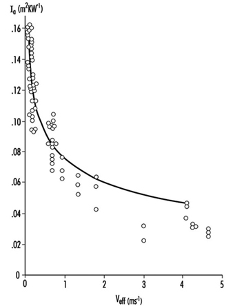
Heat transfer by radiation
Radiation is another important mechanism for heat transfer. Every surface radiates heat, and absorbs heat that is radiated from other surfaces. Radiant heat flow is approximately proportional to the temperature difference between the two exchanging surfaces. A clothing layer between the surfaces will interfere with radiative heat transfer by intercepting the energy flow; the clothing will reach a temperature that is about the average of the temperatures of the two surfaces, cutting the temperature difference between them in two, and therefore the radiant flow is decreased by a factor of two. As the number of intercepting layers is increased, the rate of heat transfer is decreased.
Multiple layers are thus effective in reducing radiant heat transfer. In battings and fibre fleeces radiation is intercepted by distributed fibres, rather than a fabric layer. The density of the fibre material (or rather the total surface of fibre material per volume of fabric) is a critical parameter for radiation transfer inside such fibre fleeces. Fine fibres provide more surface for a given weight than coarse fibres.
Fabric insulation
As a result of the conductivities of enclosed air and radiation transfer, fabric conductivity is effectively a constant for fabrics of various thicknesses and bindings. The heat insulation is therefore proportional to the thickness.
Vapour resistance of air and fabrics
Air layers also create a resistance to the diffusion of evaporated sweat from humid skin to the environment. This resistance is roughly proportional to the thickness of the clothing ensemble. For fabrics, the vapour resistance is dependent on the enclosed air and the density of the construction. In real fabrics, high density and great thickness never go together. Due to this limitation it is possible to estimate the air equivalent of fabrics that do not contain films or coatings (see figure 8). Coated fabrics or fabrics laminated to films may have unpredictable vapour resistance, which should be determined by measurement.
Figure 2. Relationship between thickness and vapour resistance (deq) for fabrics without coatings.

From Fabric and Air Layers to Clothing
Multiple layers of fabric
Some important conclusions from the heat transfer mechanisms are that highly insulating clothing is necessarily thick, that high insulation may be obtained by clothing ensembles with multiple thin layers, that a loose fit provides more insulation than a tight fit, and that insulation has a lower limit, set by the air layer that adheres to the skin.
In cold-weather clothing it is often hard to obtain thickness by using thin fabrics only. A solution is to create thick fabrics, by mounting two thin shell fabrics to a batting. The purpose of the batting is to create the air layer and keep the air inside as still as possible. There is also a drawback to thick fabrics: the more the layers are connected, the stiffer the clothing becomes, thereby restricting motion.
Clothing variety
The insulation of a clothing ensemble depends to a large extent on the design of the clothing. Design parameters which affect insulation are number of layers, apertures, fit, distribution of insulation over the body and exposed skin. Some material properties such as air permeability, reflectivity and coatings are important as well. Furthermore, wind and activity change the insulation. Is it possible to give an adequate description of clothing for the purpose of prediction of comfort and tolerance of the wearer? Various attempts have been made, based on different techniques. Most estimates of complete ensemble insulation have been made for static conditions (no motion, no wind) on indoor ensembles, because the available data were obtained from thermal mannequins (McCullough, Jones and Huck 1985). Measurements on human subjects are laborious, and results vary widely. Since the mid-1980s reliable moving mannequins have been developed and used (Olesen et al. 1982; Nielsen, Olesen and Fanger 1985). Also, improved measurement techniques allowed for more accurate human experiments. A problem that still has not been overcome completely is proper inclusion of sweat evaporation in the evaluation. Sweating mannequins are rare, and none of them has a realistic distribution of sweat rate over the body. Humans sweat realistically, but inconsistently.
Definition of clothing insulation
Clothing insulation (Icl in units of m2K/W) for steady state conditions, without radiation sources or condensation in the clothing, is defined in "Formulae and Definitions." Often I is expressed in the unit clo (not a standard international unit). One clo equals 0.155 m2K/W. The use of the unit clo implicitly means that it relates to the whole body and thus includes heat transfer by exposed body parts.
I is modified by motion and wind, as explained earlier, and after correction the result is called resultant insulation. This is a frequently used but not generally accepted term.
Distribution of clothing over the body
Total heat transfer from the body includes heat that is transferred by exposed skin (usually head and hands) and heat passing through the clothing. Intrinsic insulation (see "Formulae and Definitions") is calculated over the total skin area, not only the covered part. Exposed skin transfers more heat than covered skin and thus has a profound influence on the intrinsic insulation. This effect is enhanced by increasing wind speed. Figure 3 shows how the intrinsic insulation decreases successively due to curvature of body shapes (outer layers less effective than inner), exposed body parts (additional pathway for heat transfer) and increased wind speed (less insulation, in particular for exposed skin) (Lotens 1989). For thick ensembles the reduction in insulation is dramatic.
Figure 3. Intrinsic insulation, as it is influenced by body curvature, bare skin and wind speed.
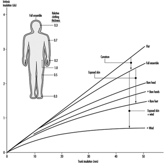
Typical ensemble thickness and coverage
Apparently both the insulation thickness and the skin coverage are important determinants of heat loss. In real life the two are correlated in the sense that winter clothing is not only thicker, but also covers a larger proportion of the body than summer wear. Figure 4 demonstrates how these effects together result in an almost linear relation between clothing thickness (expressed as volume of insulation material per unit of clothing area) and insulation (Lotens 1989). The lower limit is set by the insulation of the adjacent air and the upper limit by usability of the clothing. Uniform distribution may provide the best insulation in the cold, but it is impractical to have much weight and bulk on the limbs. Therefore the emphasis is often on the trunk, and the sensitivity of local skin to cold is adapted to this practice. Limbs play an important role in controlling human heat balance, and high insulation of the limbs limits the effectiveness of this regulation.
Figure 4. Total insulation resulting from clothing thickness and distribution over the body.
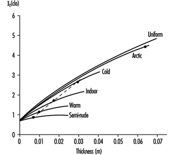
Ventilation of clothing
Trapped air layers in the clothing ensemble are subject to motion and wind, but to a different degree than the adjacent air layer. Wind creates ventilation in the clothing, both as air penetrating the fabric and by passing through apertures, while motion increases internal circulation. Havenith, Heus and Lotens (1990) found that inside clothing, motion is a stronger factor than in the adjacent air layer. This conclusion is dependent on the air permeability of the fabric, however. For highly air-permeable fabrics, ventilation by wind is considerable. Lotens (1993) showed that ventilation can be expressed as a function of effective wind speed and air permeability.
Estimates of Clothing Insulation and Vapour Resistance
Physical estimates of clothing insulation
Thickness of a clothing ensemble provides a first estimate of insulation. Typical conductivity of an ensemble is 0.08 W/mK. At an average thickness of 20 mm, that results in an Icl of 0.25 m2K/W, or 1.6 clo. However, loose-fitting parts, such as trousers or sleeves, have a much higher conductivity, more on the order of 0.15, whereas tightly packed clothing layers have a conductivity of 0.04, the famous 4 clo per inch reported by Burton and Edholm (1955).
Estimates from tables
Other methods use table values for clothing items. These items have been measured previously on a mannequin. An ensemble under investigation has to be separated into its components, and these have to be looked up in the table. Making an incorrect choice of the most similar tabulated clothing item may cause errors. In order to obtain the intrinsic insulation of the ensemble, the single insulation values have to be put in a summation equation (McCullough, Jones and Huck 1985).
Clothing surface area factor
In order to calculate total insulation, fcl has to be estimated (see "Formulae and Definitions"). A practical experimental estimate is to measure the clothing surface area, make corrections for overlapping parts, and divide by total skin area (DuBois and DuBois 1916). Other estimates from various studies show that fcl increases linearly with intrinsic insulation.
Estimate of vapour resistance
For a clothing ensemble, vapour resistance is the sum of resistance of air layers and clothing layers. Usually the number of layers varies over the body, and the best estimate is the area-weighted average, including exposed skin.
Relative vapour resistance
Evaporative resistance is less frequently used than I, because few measurements of Ccl (or Pcl) are available. Woodcock (1962) avoided this problem by defining the water vapour permeability index im as the ratio of I and R, related to the same ratio for a single air layer (this latter ratio is nearly a constant and known as the psychrometric constant S, 0.0165 K/Pa, 2.34 Km3/g or 2.2 K/torr); im= I/(R·S). Typical values for im for non-coated clothing, determined on mannequins, are 0.3 to 0.4 (McCullough, Jones and Tamura 1989). Values for im for fabric composites and their adjacent air can be measured relatively simply on a wet hotplate apparatus, but the value is actually dependent on air flow over the apparatus and the reflectivity of the cabinet in which it is mounted. Extrapolation of the ratio of R and I for clothed humans from measurements on fabrics to clothing ensembles (DIN 7943-2 1992) is sometimes attempted. This is a technically complicated matter. One reason is that R is proportional only to the convective part of I, so that careful corrections have to be made for radiative heat transfer. Another reason is that trapped air between fabric composites and clothing ensembles may be different. In fact, vapour diffusion and heat transfer can be better treated separately.
Estimates by articulated models
More sophisticated models are available to calculate insulation and water vapour resistance than the above-explained methods. These models calculate local insulation on the basis of physical laws for a number of body parts and integrate these to intrinsic insulation for the whole human shape. For this purpose the human shape is approximated by cylinders (figure ). The model by McCullough, Jones and Tamura (1989) requires clothing data for all layers in the ensemble, specified per body segment. The CLOMAN model of Lotens and Havenith (1991) requires fewer input values. These models have similar accuracy, which is better than any of the other methods mentioned, with the exception of experimental determination. Unfortunately and inevitably the models are more complex than would be desirable in a widely accepted standard.
Figure 5. Articulation of human shape in cylinders.
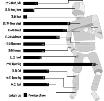
Effect of activity and wind
Lotens and Havenith (1991) also provide modifications, based on literature data, of the insulation and vapour resistance due to activity and wind. Insulation is lower while sitting than standing, and this effect is larger for highly insulating clothing. However, motion decreases insulation more than posture does, depending on the vigour of the movements. During walking both arms and legs move, and the reduction is larger than during cycling, when only the legs move. Also in this case, the reduction is larger for thick clothing ensembles. Wind decreases insulation the most for light clothing and less for heavy clothing. This effect might relate to the air permeability of the shell fabric, which is usually less for cold-weather gear.
Figure 8 shows some typical effects of wind and motion on vapour resistance for rainwear. There is no definite agreement in the literature about the magnitude of motion or wind effects. The importance of this subject is stressed by the fact that some standards, such as ISO 7730 (1994), require resultant insulation as an input when applied for active persons, or persons exposed to significant air motion. This requirement is often overlooked.
Figure 6. Decrease in vapour resistance with wind and walking for various rainwear.
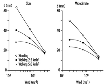
Moisture Management
Effects of moisture absorption
When fabrics can absorb water vapour, as most natural fibres do, clothing works as a buffer for vapour. This changes the heat transfer during transients from one environment to another. As a person in non-absorbing clothing steps from a dry to a humid environment, the evaporation of sweat decreases abruptly. In hygroscopic clothing the fabric absorbs vapour, and the change in evaporation is only gradual. At the same time the absorption process liberates heat in the fabric, increasing its temperature. This reduces the dry heat transfer from the skin. In first approximation, both effects cancel each other, leaving the total heat transfer unchanged. The difference with non-hygroscopic clothing is the more gradual change in evaporation from the skin, with less risk of sweat accumulation.
Vapour absorption capacity
Absorption capacity of fabric depends on the fibre type and the fabric mass. Absorbed mass is roughly proportional to the relative humidity, but is higher above 90%. The absorption capacity (called regain) is expressed as the amount of water vapour that is absorbed in 100 g of dry fibre at the relative humidity of 65%. Fabrics can be classified as follows:
- low absorption—acrylic, polyester (1 to 2 g per 100 g)
- intermediate absorption—nylon, cotton, acetate (6 to 9 g per 100 g)
- high absorption—silk, flax, hemp, rayon, jute, wool (11 to 15 g per 100 g).
Water uptake
Water retention in fabrics, often confused with vapour absorption, obeys different rules. Free water is loosely bound to fabric and spreads well sideways along capillaries. This is known as wicking. Transfer of liquid from one layer to another takes place only for wet fabrics and under pressure. Clothing may be wetted by non-evaporated (superfluous) sweat that is taken up from the skin. The liquid content of fabric may be high and its evaporation at a later moment a threat to the heat balance. This typically happens during rest after hard work and is known as after-chill. The ability of fabrics to hold liquid is more related to fabric construction than to fibre absorption capacity, and for practical purposes is usually sufficient to take up all the superfluous sweat.
Condensation
Clothing may get wet by condensation of evaporated sweat at a particular layer. Condensation occurs if the humidity is higher than the local temperature allows. In cold weather that will often be the case at the inside of the outer fabric, in extreme cold even in deeper layers. Where condensation takes place, moisture accumulates, but the temperature increases, as it does during absorption. The difference between condensation and absorption, however, is that absorption is a temporary process, whereas condensation may continue for extended times. Latent heat transfer during condensation may contribute very significantly to heat loss, which may or may not be desirable. The accumulation of moisture is mostly a drawback, because of discomfort and risk of after-chill. For profuse condensation, the liquid may be transported back to the skin, to evaporate again. This cycle works as a heat pipe and may strongly reduce the insulation of the underclothing.
Dynamic Simulation
Since the early 1900s many standards and indices have been developed to classify clothing and climates. Almost without exception these have dealt with steady states—conditions in which the climate and work were maintained long enough for a person to develop a constant body temperature. This type of work has become rare, due to improved occupational health and work conditions. The emphasis has shifted to short-duration exposure to harsh circumstances, often related to calamity management in protective clothing.
There is thus a need for dynamic simulations involving clothing heat transfer and thermal strain of the wearer (Gagge, Fobelets and Berglund 1986). Such simulations can be carried out by means of dynamic computer models that run through a specified scenario. Among the most sophisticated models to date with respect to clothing is THDYN (Lotens 1993), which allows for a wide range of clothing specifications and has been updated to include individual characteristics of the simulated person (figure 9). More models may be expected. There is a need, however, for extended experimental evaluation, and running such models is the work of experts, rather than the intelligent layperson. Dynamic models based on the physics of heat and mass transfer include all heat transfer mechanisms and their interactions—vapour absorption, heat from radiant sources, condensation, ventilation, moisture accumulation, and so on—for a wide range of clothing ensembles, including civil, work and protective clothing.
Figure 7. General description of a dynamic thermal model.
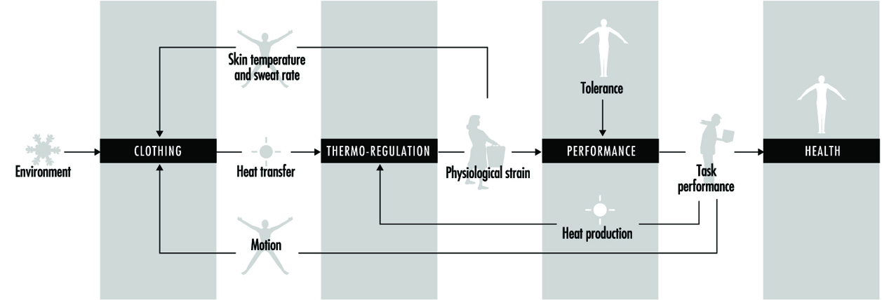
Surface Treatment of Metals
Adapted from the 3rd edition, Encyclopaedia of Occupational Health and Safety.
There is a wide variety of techniques for finishing the surfaces of metal products so that they resist corrosion, fit better and look better (see table 1). Some products are treated by a sequence of several of these techniques. This article will briefly describe some of those most commonly used.
Table 1. Summary of the hazards associated with the different metal treatment methods
|
Metal treatment method |
Hazards |
Precautions |
|
Electrolytic polishing |
Burns and irritation from caustic and corrosive chemicals |
Use appropriate personal protective equipment. Install effective exhaust ventilation. |
|
Electroplating |
Exposure to potentially cancer causing chromium and nickel; exposure to cyanides; burns and irritation from caustic and corrosive chemicals; electric shock; the process can be wet, causing slip and fall hazards; potential explosive dust generation; ergonomic hazards |
Use appropriate personal protective equipment. Install effective exhaust ventilation, often slotted, push-pull system. Clean up spills immediately. Install non-skid flooring. Use effective design of work procedures and stations to avoid ergonomic stress. |
|
Enamels and glazing |
Physical hazards from grinders, conveyers, mills; burn hazard from high temperature liquids and equipment; exposure to dusts that may cause lung disease |
Install proper machine guards, including interlocks. Use appropriate personal protective equipment. Install effective exhaust ventilation to avoid dust exposure. HEPA-filtered equipment may be necessary. |
|
Etching |
Exposure to hydrofluoric acid; burns and irritation from caustic and corrosive chemicals; burn hazard from high temperature liquids and equipment |
Implement a programme to avoid exposure to hydrofluoric acid. Use appropriate personal protective equipment. Install effective exhaust ventilation. |
|
Galvanizing |
Burn hazard from high temperature liquids, metals, and equipment; burns and irritation from caustic and corrosive chemicals; metal fume fever; potential lead exposure |
Use appropriate personal protective equipment. Install effective exhaust ventilation. Implement a lead exposure reduction/monitoring programme. |
|
Heat treatment |
Burn hazard from high temperature liquids, metals and equipment; burns and irritation from caustic and corrosive chemicals; possible explosive atmospheres of hydrogen; potential exposure to carbon monoxide; potential exposure to cyanides; fire hazard from oil quenching |
Use appropriate personal protective equipment. Install effective exhaust ventilation. Display signs warning of high temperature equipment and surfaces. Install systems to monitor the concentration of carbon monoxide. Install adequate fire-suppression systems. |
|
Metallizing |
Burn hazard from high temperature metals and equipment; possible explosive atmospheres of dust, acetylene; zinc metal fume fever |
Install adequate fire suppression systems. Properly separate chemicals and gases. Use appropriate personal protective equipment. Install effective exhaust ventilation. |
|
Phosphating |
Burns and irritation from caustic and corrosive chemicals |
Use appropriate personal protective equipment. Install effective exhaust ventilation. |
|
Plastics coating |
Exposure to chemical sensitizers |
Seek alternatives to sensitizers. Use appropriate personal protective equipment. Install effective exhaust ventilation. |
|
Priming |
Exposure to various solvents which are potentially toxic and flammable, exposure to chemical sensitizers, exposure to potentially carcinogenic chromium |
Seek alternatives to sensitizers. Use appropriate personal protective equipment. Install effective exhaust ventilation. Properly separate chemicals/gases. |
Before any of these techniques can be applied, the products must be thoroughly cleaned. A number of methods of cleaning are used, individually or in sequence. They include mechanical grinding, brushing and polishing (which produce metallic or oxidic dust—aluminium dust may be explosive), vapour degreasing, washing with organic grease solvents, “pickling” in concentrated acid or alkaline solutions and electrolytic degreasing. The last involves immersion in baths containing cyanide and concentrated alkali in which electrolytically formed hydrogen or oxygen remove the grease, resulting in “blank” metal surfaces that are free from oxides and grease. The cleaning is followed by adequate rinsing and drying of the product.
Proper design of the equipment and effective LEV will reduce some of the risk. Workers exposed to the hazard of splashes must be provided with protective goggles or eye shields and protective gloves, aprons and clothing. Showers and eyewash fountains should be nearby and in good working order, and splashes and spills should be washed away promptly. With electrolytic equipment, the gloves and shoes must be non-conducting, and other standard electrical precautions, such as the installation of ground fault circuit interrupters and lockout/tagout procedures should be followed.
Treatment Processes
Electrolytic polishing
Electrolytic polishing is used to produce a surface of improved appearance and reflectivity, to remove excess metal to accurately fit the required dimensions and to prepare the surface for inspection for imperfections. The process involves preferential anodic dissolution of high spots on the surface after vapour degreasing and hot alkaline cleaning. Acids are frequently used as the electrolyte solutions; accordingly, adequate rinsing is required afterwards.
Electroplating
Electroplating is a chemical or electrochemical process for applying a metallic layer to the product—for example, nickel to protect against corrosion, hard chromium to improve the surface properties or silver and gold to beautify it. Occasionally, non-metallic materials are used. The product, wired as the cathode, and an anode of the metal to be deposited are immersed in an electrolyte solution (which can be acidic, alkaline or alkaline with cyanide salts and complexes) and connected externally to a source of direct current. The positively charged cations of the metallic anode migrate to the cathode, where they are reduced to the metal and deposited as a thin layer (see figure 1). The process is continued until the new coating reaches the desired thickness, and the product is then washed, dried and polished.
Figure 1. Electroplating: Schematic representation
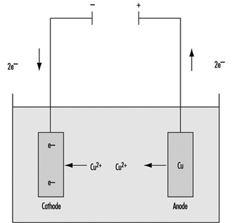
Anode: Cu → Cu+2 + 2e- ; Cathode: Cu+2 + 2e- → Cu
In electroforming, a process closely related to electroplating, objects moulded of, for example, plaster or plastic are made conductive by the application of graphite and then are connected as the cathode so that the metal is deposited on them.
In anodization, a process that has become increasingly important in recent years, products of aluminium (titanium and other metals are also used) are connected as the anode and immersed in dilute sulphuric acid. However, instead of the formation of positive aluminium ions and migrating for deposition on the cathode, they are oxidized by the oxygen atoms arising at the anode and become bound to it as an oxide layer. This oxide layer is partially dissolved by the sulphuric acid solution, making the surface layer porous. Subsequently, coloured or light-sensitive materials can be deposited in these pores, as in the fabrication of nameplates, for example.
Enamels and glazes
Vitreous enamel or porcelain enamel is used to give a high heat-, stain- and corrosion-resistant covering to metals, usually iron or steel, in a wide range of fabricated products including bath tubs, gas and electric cookers, kitchen ware, storage tanks and containers, and electrical equipment. In addition, enamels are used in the decoration of ceramics, glass, jewellery and decorative ornaments. The specialized use of enamel powders in the production of such ornamental ware as Cloisonné and Limoges has been known for centuries. Glazes are applied to pottery ware of all kinds.
The materials used in the manufacture of vitreous enamels and glazes include:
- refractories, such as quartz, feldspar and clay
- fluxes, such as borax (sodium borate decahydrate), soda ash (anhydrous sodium carbonate), sodium nitrate, fluorspar, cryolite, barium carbonate, magnesium carbonate, lead monoxide, lead tetroxide and zinc oxide
- colours, such as oxides of antimony, cadmium, cobalt, iron, nickel, manganese, selenium, vanadium, uranium and titanium
- opacifiers, such as oxides of antimony, titanium, tin and zirconium, and sodium antimoninate
- electrolytes, such as borax, soda ash, magnesium carbonate and sulphate, sodium nitrite and sodium aluminate
- flocculating agents, such as clay, gums, ammonium alginate, bentonite and colloidal silica.
The first step in all types of vitreous enamelling or glazing is the making of the frit, the enamel powder. This involves preparation of the raw materials, smelting and frit handing.
After careful cleaning of the metal products (e.g., shot blasting, pickling, degreasing), the enamel may be applied by a number of procedures:
- In the wet process, the object is dipped into the aqueous enamel slip, withdrawn and allowed to drain or, in “slushing”, the enamel slip is thicker and must be shaken from the object.
- In the dry process, the ground-coated object is heated to the enamelling temperature and then dry enamel powder is dusted through sieves onto it. The enamel sinters into place and, when the object is returned to the furnace, it melts down to a smooth surface.
- Spray application is being used increasingly, usually in a mechanized operation. It requires a cabinet under exhaust ventilation.
- Decorative enamels are usually applied by hand, using brushes or similar tools.
- Glazes for porcelain and pottery articles are usually applied by dipping or spraying. Although some dipping operations are being mechanized, pieces are usually dipped by hand in the domestic porcelain industry. The object is held in the hand, dipped into a large tub of glaze, the glaze is removed by a flick of the wrist and the object is placed in a dryer. An enclosed hood or cabinet with efficient exhaust ventilation should be provided when the glaze is sprayed.
The prepared objects are then “fired” in a furnace or kiln, which usually is gas fuelled.
Etching
Chemical etching produces a satin or matte finish. Most frequently, it is used as a pre-treatment prior to anodizing, lacquering, conversion coating, buffing or chemical brightening. It is most frequently applied to aluminium and stainless steel, but is also used for many other metals.
Aluminium is usually etched in alkaline solutions containing various mixtures of sodium hydroxide, potassium hydroxide, trisodium phosphate and sodium carbonate, together with other ingredients to prevent sludge formation. One of the most common processes uses sodium hydroxide at a concentration of 10 to 40 g/l maintained at a temperature of 50 to 85°C with an immersion time as long as 10 minutes.
The alkaline etching is usually preceded and followed by treatment in various mixtures of hydrochloric, hydrofluoric, nitric, phosphoric, chromic or sulphuric acid. A typical acid treatment involves immersions of 15 to 60 seconds in a mixture of 3 parts by volume of nitric acid and 1 part by volume of hydrofluoric acid that is maintained at a temperature of 20°C.
Galvanizing
Galvanizing applies a zinc coating to a variety of steel products to protect against corrosion. The product must be clean and oxide-free for the coating to adhere properly. This usually involves a number of cleaning, rinsing, drying or annealing processes before the product enters the galvanizing bath. In “hot dip” galvanizing, the product is passed through a bath of molten zinc; “cold” galvanizing is essentially electroplating, as described above.
Manufactured products are usually galvanized in a batch process, while the continuous strip method is used for steel strip, sheet or wire. Flux may be employed to maintain satisfactory cleaning of both the product and the zinc bath and to facilitate drying. A prefluxing step may be followed by an ammonium chloride flux cover on the surface of the zinc bath, or the latter may be used alone. In galvanizing pipe, the pipe is immersed in a hot solution of zinc ammonium chloride after cleaning and before the pipe enters the molten zinc bath. The fluxes decompose to form irritating hydrogen chloride and ammonia gas, requiring LEV.
The various types of continuous hot-dip galvanizing differ essentially in how the product is cleaned and whether the cleaning is done on-line:
- cleaning by flame oxidation of the surface oils with subsequent reduction in the furnace and annealing done in-line
- electrolytic cleaning done prior to in-line annealing
- cleaning by acid pickling and alkali cleaning, using a flux prior to the preheat furnace and annealing in a furnace before galvanizing
- cleaning by acid pickling and alkali cleaning, eliminating the flux and preheating in a reducing gas (e.g., hydrogen) prior to galvanizing.
The continuous galvanizing line for light-gauge strip steel omits pickling and the use of flux; it uses alkaline cleaning and maintains the clean surface of the strip by heating it in a chamber or furnace with a reducing atmosphere of hydrogen until it passes below the surface of the molten zinc bath.
Continuous galvanizing of wire requires annealing steps, usually with a molten lead pan in front of the cleaning and galvanizing tanks; air or water cooling; pickling in hot, dilute hydrochloric acid; rinsing; application of a flux; drying; and then galvanizing in the molten zinc bath.
A dross, an alloy of iron and zinc, settles to the bottom of the molten zinc bath and must be removed periodically. Various types of materials are floated on the surface of the zinc bath to prevent oxidation of the molten zinc. Frequent skimming is needed at the points of entry and exit of the wire or strip being galvanized.
Heat treatment
Heat treatment, the heating and cooling of a metal which remains in the solid state, is usually an integral part of the processing of metal products. It almost always involves a change in the crystalline structure of the metal which results in a modification of its properties (e.g., annealing to make the metal more malleable, heating and slow cooling to reduce hardness, heating and quenching to increase hardness, low-temperature heating to minimize internal stresses).
Annealing
Annealing is a “softening” heat treatment widely used to allow further cold working of the metal, improve machinability, stress-relieve the product before it is used and so on. It involves heating the metal to a specific temperature, holding it at that temperature for a specific length of time and allowing it to cool at a particular rate. A number of annealing techniques are used:
- Blue annealing, in which a layer of blue oxide is produced on the surface of iron-based alloys
- Bright annealing, which is carried out in a controlled atmosphere to minimize surface oxidation
- Close annealing or box annealing, a method in which both ferrous and non-ferrous metals are heated in a sealed metal container with or without a packing material and then slowly cooled
- Full annealing, usually carried out in a protective atmosphere, aimed at obtaining the maximum softness economically feasible
- Malleablizing, a special kind of anneal given to iron castings to make them malleable by transforming the combined carbon in the iron to fine carbon (i.e., graphite)
- Partial annealing, a low-temperature process to remove internal stresses induced in the metal by cold working
- Sub-critical or spheroidizing annealing, which produces improved machinability by allowing the iron carbide in the crystalline structure to acquire a spheroid shape.
Age-hardening
Age-hardening is a heat treatment often used on aluminium-copper alloys in which the natural hardening that takes place in the alloy is accelerated by heating to about 180°C for about 1 hour.
Homogenizing
Homogenizing, usually applied to ingots or powdered metal compacts, is designed to remove or greatly reduce segregation. It is achieved by heating to a temperature about 20°C below the metal’s melting point for about 2 hours or more and then quenching.
Normalizing
A process similar to full annealing, ensures the uniformity of the mechanical properties to be obtained and also produces greater toughness and resistance to mechanical loading.
Patenting
Patenting is a special type of annealing process that is usually applied to materials of small cross-section which are intended to be drawn (e.g., 0.6% carbon steel wire). The metal is heated in an ordinary furnace to above the transformation range and then passes from the furnace directly into, for example, a lead bath held at a temperature of about 170°C.
Quench-hardening and tempering
An increase in hardness can be produced in an iron-based alloy by heating to above the transformation range and rapidly cooling to room temperature by quenching in oil, water or air. The article is often too highly stressed to be put into service and, in order to increase its toughness, it is tempered by reheating to a temperature below the transformation range and allowing it to cool at the desired rate.
Martempering and austempering are similar processes except that the article is quenched, for example, in a salt or lead bath held at a temperature of 400°C.
Surface- and case-hardening
This is another heat-treatment process applied most frequently to iron-based alloys, which allows the surface of the object to remain hard while its core remains relatively ductile. It has a number of variations:
- Flame hardening involves hardening the surfaces of the object (e.g., gear teeth, bearings, slideways) by heating with a high-temperature gas torch and then quenching in oil, water or another suitable medium.
- Electrical induction hardening is similar to flame hardening except that the heating is produced by eddy currents induced in the surface layers.
- Carburizing increases the carbon content of the surface of an iron-based alloy by heating the object in a solid, liquid or gaseous carbonaceous medium (e.g., solid charcoal and barium carbonate, liquid sodium cyanide and sodium carbonate, gaseous carbon monoxide, methane and so on) at a temperature of about 900°C.
- Nitriding increases the nitrogen content of the surface of a special low-alloy cast iron or steel object by heating it in a nitrogenous medium, usually ammonia gas, at about 500 to 600°C.
- Cyaniding is a method of case-hardening in which the surface of a low-carbon steel object is enriched in both carbon and nitrogen simultaneously. It usually involves heating the object for 1 hour in a bath of molten 30% sodium cyanide at 870°C, and then quenching in oil or water.
- Carbo-nitriding is a gaseous process for the simultaneous absorption of carbon and nitrogen into the surface layer of steel by heating it to 800 to 875°C in an atmosphere of a carburizing gas (see above) and a nitriding gas (e.g., 2 to 5% anhydrous ammonia).
Metallizing
Metallizing, or metal spraying, is a technique for applying a protective metallic coating to a mechanically roughened surface by spraying it with molten droplets of metal. It is also used to build up worn or corroded surfaces and for salvaging badly-machined component parts. The process is widely known as Schooping, after the Dr. Schoop who invented it.
It uses the Schooping gun, a hand-held, pistol-shaped spray gun through which the metal in wire form is fed into a fuel gas/oxygen blowpipe flame which melts it and, using compressed air, sprays it onto the object. The heat source is a mixture of oxygen and either acetylene, propane or compressed natural gas. The coiled wire is usually straightened before being fed into the gun. Any metal that can be made into a wire may be used; the gun can also accept the metal in powder form.
Vacuum metallizing is a process in which the object is placed in a vacuum jar into which the coating metal is sprayed.
Phosphating
Phosphating is used mainly on mild and galvanized steel and aluminium to augment the adhesion and corrosion resistance of paint, wax and oil finishes. It is also used to form a layer which acts as a parting film in the deep drawing of sheet metal and improves its wear resistance. It essentially consists of allowing the metal surface to react with a solution of one or more phosphates of iron, zinc, manganese, sodium or ammonium. Sodium and ammonium phosphate solutions are used for combined cleaning and phosphating. The need to phosphate multi-metal objects and the desire to increase line speeds in automated operations have led to reducing reaction times by the addition of accelerators such as fluorides, chlorates, molybdates and nickel compounds to the phosphating solutions.To reduce crystal size and, consequently, increase the flexibility of zinc phosphate coatings, crystal refining agents such as tertiary zinc phosphate or titanium phosphate are added to the pre-treatment rinse.
The phosphating sequence typically includes the following steps:
- hot caustic cleaning
- brushing and rinsing
- further hot caustic cleaning
- conditioning water rinse
- spraying or dipping in hot solutions of acid phosphates
- cold water rinse
- warm chromic acid rinse
- another cold water rinse
- drying.
Priming
Organic paint primers are applied to metal surfaces to promote the adhesion of subsequently applied paints and to retard corrosion at the paint-metal interface. The primers usually contain resins, pigments and solvents and may be applied to the prepared metal surfaces by brush, spray, immersion, roller coating or electrophoresis.
The solvents may be any combination of aliphatic and aromatic hydrocarbons, ketones, esters, alcohols and ethers. The most commonly used resins are polyvinyl butynol, phenolic resins, drying oil alkyds, epoxidized oils, epoxyesters, ethyl silicates and chlorinated rubbers. In complex primers, cross-linking agents such as tetraethylene pentamine, pentaethylene hexamine, isocyanates and urea formaldehyde are used. Inorganic pigments used in primer formulations include lead, barium, chromium, zinc and calcium compounds.
Plastic coating
Plastic coatings are applied to metals in liquid form, as powders which are subsequently cured or sintered by heating, or in the form of fabricated sheets which are laminated to the metal surface with an adhesive. The most commonly used plastics include polyethylene, polyamides (nylons) and PVC. The latter may include plasticizers based on monomeric and polymeric esters and stabilizers such as lead carbonate, fatty acid salts of barium and cadmium, dibutyltin dilaurate, alkyltin mercaptides and zinc phosphate. Although generally of low toxicity and non-irritating, some of the plasticizers are skin sensitizers.
Hazards and Their Prevention
As might be deduced from the complexity of the processes outlined above, there is a large variety of safety and health hazards associated with the surface treatment of metals. Many are regularly encountered in manufacturing operations; others are presented by the uniqueness of the techniques and materials employed. Some are potentially life threatening. By and large, however, they can be prevented or controlled.
Workplace design
The workplace should be designed to allow the delivery of raw materials and supplies and the removal of the finished products without interfering with the ongoing processing. Since many of the chemicals are flammable or prone to react when mixed, proper separation in storage and in transit is essential. Many of the metal finishing operations involve liquids, and when leaks, spills or splashes of acids or alkalis occur they must be washed away promptly. Accordingly, adequately drained, slip-resistant floors must be provided. Housekeeping must be diligent to keep the work areas and other spaces clean and free from accumulations of materials. Systems for disposal of solid and liquid wastes and effluents from furnaces and exhaust ventilation must be designed with environmental concerns in mind.
Work stations and work assignments should use ergonomic principles to minimize strains, sprains, excessive fatigue and RSIs. Machine guards must have automatic lockout so the machine is de-energized if the guard is removed. Splash guards are essential. Because of the danger of splashes of hot acid and alkali solutions, eyewash fountains and whole-body showers must be installed within easy reach. Signs should be posted to warn other production and maintenance personnel of such dangers as chemical baths and hot surfaces.
Chemical assessment
All chemicals should be evaluated for potential toxicity and physical hazards, and less hazardous materials should be substituted where possible. However, since the less toxic material may be more flammable, the hazard of fire and explosion must also be considered. In addition, the chemical compatibility of materials must be considered. For example, mixing of nitrate and cyanide salts by accident could cause an explosion due to the strong oxidizing properties of nitrates.
Ventilation
Most of the metal coating processes require LEV that is strategically placed to draw the vapours or other contaminants away from the worker. Some systems push fresh air across the tank to “push” airborne contaminants to the exhaust side of the system. Fresh air intakes must be located away from exhaust vents so that potentially toxic gases are not recirculated.
Personal protective equipment
Processes should be engineered to prevent potentially toxic exposures, but since they cannot always be totally avoided, employees will have to be provided with appropriate PPE (e.g., goggles with or without face shields as appropriate, gloves, aprons or coveralls and shoes). Because many of the exposures involve hot corrosive or caustic solutions, the protective items should be insulated and chemical-resistant. If there is possible exposure to electricity, PPE should be non-conductive. PPE must be available in adequate quantity to allow contaminated, wet items to be cleaned and dried before re-using them. Insulated gloves and other protective clothing should be available where there is the risk of thermal burns from hot metal, furnaces and so on.
An important adjunct is the availability of wash-up facilities and clean lockers and dressing rooms, so that workers’ clothing remains uncontaminated and workers do not carry toxic materials back into their homes.
Employee training and supervision
Employee education and training are essential both when new to the job or when there have been changes in the equipment or the process. MSDSs must be provided for each of the chemical products which explain the chemical and physical hazards, in languages and at educational levels that ensure they will be understood by the workers. Competence testing and periodic retraining will assure that workers have retained the needed information. Close supervision is advisable to make sure that the proper procedures are being followed.
Selected hazards
Certain hazards are unique to the metal coating industry and deserve special consideration.
Alkaline and acid solutions
The heated alkaline and acid solutions used in cleaning and treatment of metals are particularly corrosive and caustic. They are irritating to the skin and mucous membranes and are especially dangerous when splashed into the eye. Eyewash fountains and emergency showers are essential. Proper protective clothing and goggles will guard against the inevitable splashes; when a splash reaches the skin, the area should be immediately and copiously rinsed with cool, clean water for at least 15 minutes; medical attention may be necessary, particularly when the eye is involved.
Care should be exercised when utilizing chlorinated hydrocarbons as phosgene may result from a reaction of the chlorinated hydrocarbon, acids and metals. Nitric and hydrofluoric acid are particularly dangerous when their gases are inhaled, because it may take 4 hours or more before the effects on the lungs become apparent. Bronchitis, pneumonitis and even potentially fatal pulmonary oedema may appear belatedly in a worker who apparently had no initial effect from the exposure. Prompt prophylactic medical treatment and, often, hospitalization are advisable for workers who have been exposed. Skin contact with hydrofluoric acid can cause severe burns without pain for several hours. Prompt medical attention is essential.
Dust
Metallic and oxidic dusts are a particular problem in grinding and polishing operations, and are most effectively removed by LEV as they are created. Ductwork should be designed to be smooth and air velocity should be sufficient to keep the particulates from settling out of the air stream. Aluminium and magnesium dust may be explosive and should be collected in a wet trap. Lead has become less of a problem with the decline of its use in ceramics and porcelain glazes, but it remains the ubiquitous occupational hazard and must always be guarded against. Beryllium and its compounds have received interest recently due to the possibility of carcinogenicity and chronic beryllium disease.
Certain operations present a risk of silicosis and pneumoconiosis: the calcining, crushing and drying of flint, quartz or stone; the sieving, mixing and weighing out of these substances in the dry state; and the charging of furnaces with such materials. They also represent a danger when they are used in a wet process and are splashed about the workplace and on workers’ clothing, to become dusts again when they dry out. LEV and rigorous cleanliness and personal hygiene are important preventive measures.
Organic solvents
Solvents and other organic chemicals used in degreasing and in certain processes are dangerous when inhaled. In the acute phase, their narcotic effects may lead to respiratory paralysis and death. In chronic exposure, toxicity of the central nervous system and liver and kidney damage are most frequent. Protection is provided by LEV with a safety zone of at least 80 to 100 cm between the source and the breathing area of the worker. Bench ventilation must also be installed to remove residual vapours from the finished workpieces. Defatting of the skin by organic solvents may be a precursor of dermatitis. Many solvents are also flammable.
Cyanide
Baths containing cyanides are frequently used in electrolytic degreasing, electroplating and cyaniding. Reaction with acid will form the volatile, potentially lethal hydrogen cyanide (prussic acid). The lethal concentration in air is 300 to 500 ppm. Fatal exposures may also result from skin absorption or ingestion of cyanides. Optimum cleanliness is essential for workers using cyanide. Food should not be eaten before washing, and should never be in the work area. Hands and clothing must be carefully cleaned following a potential cyanide exposure.
First aid measures for cyanide poisoning include transport into the open air, removal of contaminated clothing, copious washing of the exposed areas with water, oxygen therapy and inhalation of amyl nitrite. LEV and skin protection are essential.
Chromium and nickel
Chromic and nickel compounds used in galvanic baths in electroplating may be hazardous. Chromium compounds can cause burns, ulceration and eczema of the skin and mucosa and a characteristic perforation of the nasal septum. Bronchial asthma may occur. Nickel salts can cause obstinate allergic or toxic-irritative skin injury. There is evidence that both chromium and nickel compounds may be carcinogenic. LEV and skin protection are essential.
Furnaces and ovens
Special precautions are needed when working with the furnaces employed, for example, in the heat treatment of metals where components are handled at high temperatures and the materials used in the process may either be toxic or explosive or both. The gaseous media (atmospheres) in the furnace may react with the metal charge (oxidizing or reducing atmospheres) or they may be neutral and protective. Most of the latter contain up to 50% hydrogen and 20% carbon monoxide, which, in addition to being combustible, form highly explosive mixtures with air at elevated temperatures. The ignition temperature varies from 450 to 750 °C, but a local spark may cause ignition even at lower temperatures. The danger of explosion is greater when the furnace is being started up or shut down. Since a cooling furnace tends to suck in air (a particular danger when the fuel or power supply is interrupted), a supply of inert gas (e.g., nitrogen or carbon dioxide) should be available for purging when the furnace is shut down as well as when a protective atmosphere is introduced into a hot furnace.
Carbon monoxide is perhaps the greatest hazard from furnaces and ovens. Since it is colourless and odourless, it frequently reaches toxic levels before the worker becomes aware of it. Headache is one of the earliest symptoms of toxicity, and, therefore, a worker developing a headache on the job should immediately be removed into fresh air. Danger zones include recessed pockets in which the carbon monoxide may collect; it should be remembered that brickwork is porous and may retain the gas during normal purging and emit it when the purging is completed.
Lead furnaces may be dangerous since lead tends to vaporize quite rapidly at temperatures above 870°C. Accordingly, an effective fume extraction system is required. A pot breakage or failure may also be hazardous; a sufficiently large well or pit should be provided to capture the molten metal if this occurs.
Fire and explosion
Many of the compounds used in metal coating are flammable and, under certain circumstances, explosive. For the most part, the furnaces and drying ovens are gas fired, and special precautions such as flame-failure devices at burners, low-pressure cut-off valves in the supply lines and explosion relief panels in the structure of the stoves should be installed. In electrolytic operations, hydrogen formed in the process may collect at the surface of the bath and, if not exhausted, may reach explosive concentrations. Furnaces should be properly ventilated and burners protected from being clogged by dripping material.
Oil quenching is also a fire hazard, especially if the metal charge is not completely immersed. Quenching oils should have a high flashpoint, and their temperature should not exceed 27°C.
Compressed oxygen and fuel gas cylinders used in metallizing are fire and explosion hazards if not stored and operated properly. See the article “Welding and thermal cutting” in this chapter for detailed precautions.
As required by local ordinances, firefighting equipment, including alarms, should be provided and maintained in working order, and the workers drilled in using it properly.
Heat
The use of furnaces, open flames, ovens, heated solutions and molten metals inevitably presents the risk of excessive heat exposure, which is compounded in hot, humid climates and, particularly, by occlusive protective garments and gear. Complete air conditioning of a plant may not be economically feasible, but supplying cooled air in local ventilation systems is helpful. Rest breaks in cool surroundings and adequate fluid intake (fluids taken at the work station should be free of toxic contaminants) will help to avert heat toxicity. Workers and supervisors should be trained in the recognition of heat stress symptoms.
Conclusion
Surface treatment of metals involves a multiplicity of processes entailing a broad range of potentially toxic exposures, most of which can be prevented or controlled by the diligent application of well-recognized preventive measures.
Industrial Lubricants, Metal Working Fluids and Automotive Oils
The industrial revolution could not have occurred without the development of refined petroleum-based industrial oils, lubricants, cutting oils and greases. Prior to the discovery in the 1860s that a superior lubricant could be produced by distilling crude oil in a vacuum, industry depended on naturally occurring oils and animal fats such as lard and whale sperm oil for lubricating moving parts. These oils and animal products were especially susceptible to melting, oxidation and breakdown from exposure to heat and moisture produced by the steam engines which powered almost all industrial equipment at that time. The evolution of petroleum-based refined products has continued from the first lubricant, which was used to tan leather, to modern synthetic oils and greases with longer service life, superior lubricating qualities and better resistance to change under varying temperatures and climatic conditions.
Industrial Lubricants
All moving parts on machinery and equipment require lubrication. Although lubrication may be provided by dry materials such as Teflon or graphite, which are used in parts such as small electrical motor bearings, oils and greases are the most commonly used lubricants. As the complexity of the machinery increases, the requirements for lubricants and metal process oils become more stringent. Lubricating oils now range from clear, very thin oils used to lubricate delicate instruments, to thick, tar-like oils used on large gears such as those which turn steel mills. Oils with very specific requirements are used both in the hydraulic systems and to lubricate large computer-operated machine tools such as those used in the aerospace industry to produce parts with extremely close tolerances. Synthetic oils, fluids and greases, and blends of synthetic and petroleum-based oils, are used where extended lubricant life is desired, such as sealed-for-life electric motors, where the increased time between oil changes offsets the difference in cost; where extended temperature and pressure ranges exist, such as in aerospace applications; or where it is difficult and expensive to re-apply the lubricant.
Industrial Oils
Industrial oils such as spindle and lubricating oils, gear lubricants, hydraulic and turbine oils and transmission fluids are designed to meet specific physical and chemical requirements and to operate without discernible change for extended periods under varying conditions. Lubricants for aerospace use must meet entirely new conditions, including cleanliness, durability, resistance to cosmic radiation and the ability to operate in extremely cold and hot temperatures, without gravity and in a vacuum.
Transmissions, turbines and hydraulic systems contain fluids which transfer force or power, reservoirs to hold the fluids, pumps to move the fluids from one place to another and auxiliary equipment such as valves, piping, coolers and filters. Hydraulic systems, transmissions and turbines require fluids with specific viscosities and chemical stability to operate smoothly and provide the controlled transfer of power. The characteristics of good hydraulic and turbine oils include a high viscosity index, thermal stability, long life in circulating systems, deposit resistance, high lubricity, anti-foam capabilities, rust protection and good demulsibility.
Gear lubricants are designed to form strong, tenacious films which provide lubrication between gears under extreme pressure. The characteristics of gear oils include good chemical stability, demulsibility and resistance to viscosity increase and deposit formation. Spindle oils are thin, extremely clean and clear oils with lubricity additives. The most important characteristics for way oils—used to lubricate two flat sliding surfaces where there is high pressure and slow speed—are lubricity and tackiness to resist squeezing out and resistance to extreme pressure.
Cylinder and compressor oils combine the characteristics of both industrial and automotive oils. They should resist accumulation of deposits, act as a heat transfer agent (internal combustion engine cylinders), provide lubrication for cylinders and pistons, provide a seal to resist blow-back pressure, have chemical and thermal stability (especially vacuum pump oil), have a high viscosity index and resist water wash (steam-operated cylinders) and detergency.
Automotive Engine Oils
Manufacturers of internal combustion engines and organizations, such as the Society of Automotive Engineers (SAE) in the United States and Canada, have established specific performance criteria for automotive engine oils. Automotive gasoline and diesel engine oils are subjected to a series of performance tests to determine their chemical and thermal stability, corrosion resistance, viscosity, wear protection, lubricity, detergency and high and low temperature performance. They are then classified according to a code system which allows consumers to determine their suitability for heavy-duty use and for different temperatures and viscosity ranges.
Oils for automotive engines, transmissions and gear cases are designed with high viscosity indexes to resist changes in viscosity with temperature changes. Automotive engine oils are especially formulated to resist breakdown under heat as they lubricate internal combustion engines. Internal combustion engine oils must not be too thick to lubricate the internal moving parts when an engine starts up in cold weather, and they must not thin out as the engine heats up when operating. They should resist carbon build-up on valves, rings and cylinders and the formation of corrosive acids or deposits from moisture. Automotive engine oils contain detergents designed to hold carbon and metallic wear particles in suspension so that they can be filtered out as the oil circulates and not accumulate on internal engine parts and cause damage.
Cutting Fluids
The three types of cutting fluids used in industry are mineral oils, soluble oils and synthetic fluids. Cutting oils are typically a blend of high-quality, high-stability mineral oils of various viscosities together with additives to provide specific characteristics depending on the type of material being machined and the work performed. Soluble water-in-oil cutting fluids are mineral oils (or synthetic oils) which contain emulsifiers and special additives including defoamants, rust inhibitors, detergents, bactericides and germicides. They are diluted with water in varying ratios before being used. Synthetic cutting fluids are solutions of non-petroleum-based fluids, additives and water, rather than emulsions, some of which are fire resistant for machining specific metals. Semi-synthetic fluids contain 10 to 15% mineral oil. Some special fluids have both lubricating oil and cutting fluid characteristics due to the tendency of fluids to leak and intermix in certain machine tools such as multi-spindle, automatic screw machines.
The desired characteristics of cutting fluids depend on the composition of the metal being worked on, the cutting tool being used and the type of cutting, planing or shaping operation performed. Cutting fluids improve and enhance the metal working process by cooling and lubrication (i.e., protecting the edge of the cutting tool). For example, when working on a soft metal which creates a lot of heat, cooling is the most important criterion. Improved cooling is provided by using a light oil (such as kerosene) or water-based cutting fluid. Control of the built-up edge on cutting tools is provided by anti-weld or anti-wear additives such as sulphur, chlorine or phosphorus compounds. Lubricity, which is important when working on steel to overcome the abrasiveness of iron sulphide, is provided by synthetic and animal fats or sulphurized sperm oil additives.
Other Metal Working and Process Oils
Grinding fluids are designed to provide cooling and prevent metal build-up on grinding wheels. Their characteristics include thermal and chemical stability, rust protection (soluble fluids), preventing gummy deposits upon evaporation and a safe flashpoint for the work performed.
Quench oils, which require high stability, are used in metal treating to control the change of the molecular structure of steel as it cools. Quenching in lighter oil is used to case harden small, inexpensive steel parts. A slower quench rate is used to produce machine tool steels which are fairly hard on the outside with lower internal stress. A gapped or multi-phase quenching oil is used to treat high carbon and alloy steels.
Roll oils are specially formulated mineral or soluble oils which lubricate and provide a smooth finish to metal, particularly aluminium, copper and brass, as it goes through hot and cold rolling mills. Release oils are used to coat dies and moulds to facilitate the release of the formed metal parts. Tanning oils are still used in the felt and leather-making industry. Transformer oils are specially formulated dielectric fluids used in transformers and large electric breakers and switches.
Heat transfer oils are used in open or closed systems and may last up to 15 years in service. The primary characteristics are good thermal stability as systems operate at temperatures from 150 to 315°C, oxidation stability and high flashpoint. Heat transfer oils are normally too viscous to be pumped at ambient temperatures and must be heated to provide fluidity.
Petroleum solvents are used to clean parts by spraying, dripping or dipping. The solvents remove oil and emulsify dirt and metal particles. Rust preventive oils may be either solvent or water based. They are applied to stainless steel coils, bearings and other parts by dipping or spraying, and leave polarized or wax films on the metal surfaces for fingerprint and rust protection and water displacement.
Greases
Greases are mixtures of fluids, thickeners and additives used to lubricate parts and equipment which cannot be made oil-tight, which are hard to reach or where leaking or splashed liquid lubricants might contaminate products or create a hazard. They have a wide range of applications and performance requirements, from lubricating jet engine bearings at sub-zero temperatures to hot rolling mill gears, and resisting acid or water washout, as well as the continuous friction created by railroad car wheel roller bearings.
Grease is made by the blending of metallic soaps (salts of long-chained fatty acids) into a lubricating oil medium at temperatures of 205 to 315°C. Synthetic greases may use di-esters, silicone or phosphoric esters and polyalkyl glycols as fluids. The characteristics of the grease depend to a great extent upon the particular fluid, metallic element (e.g., calcium, sodium, aluminium, lithium and so on) in the soap and the additives used to improve performance and stability and to reduce friction. These additives include extreme-pressure additives which coat the metal with a thin layer of non-corrosive metallic sulphur compounds, lead naphthenate or zinc dithiophosphate, rust inhibitors, anti-oxidants, fatty acids for added lubricity, tackiness additives, colour dyes for identification and water inhibitors. Some greases may contain graphite or molybdenum fillers which coat the metallic parts and provide lubrication after the grease has run out or decomposed.
Industrial Lubricants, Grease and Automotive Engine Oil Additives
In addition to using high-quality lubricant base stocks with chemical and thermal stability and high viscosity indexes, additives are needed to enhance the fluid and provide specific characteristics required in industrial lubricants, cutting fluids, greases and automotive engine oils. The most commonly used additives include but are not limited to the following:
- Anti-oxidants. Oxidation inhibitors, such as 2,6-ditertiary butyl, paracresol and phenyl naphthylamine, reduce the rate of deterioration of oil by breaking up the long-chain molecules which form when exposed to oxygen. Oxidation inhibitors are used to coat metals such as copper, zinc and lead to prevent contact with the oil so they will not act as catalysts, speeding up oxidation and forming acids which attack other metals.
- Foam inhibitors. Defoamants, such as silicones and polyorganic silioxanes, are used in hydraulic oils, gear oils, transmission fluids and turbine oils to reduce surface film tension and remove air entrapped in the oil by pumps and compressors, in order to maintain constant hydraulic pressure and prevent cavitation.
- Corrosion inhibitors. Anti-rust additives, such as lead naphthenate and sodium sulphonate, are used to prevent rust from forming on metallic parts and systems where circulating oil has been contaminated with water or by moist air which entered system reservoirs as they cooled down when the equipment or machinery was not in use.
- Anti-wear additives. Anti-wear additives, such as tricresylphosphate, form polar compounds which are attracted to metal surfaces and provide a physical layer of additional protection in the event that the oil film is not sufficient.
- Viscosity index improvers. Viscosity index improvers help oils resist the effects of temperature changes. Unfortunately, their effectiveness diminishes with extended use. Synthetic oils are designed with very high viscosity indexes, allowing them to maintain their structure over wider temperature ranges and for much longer periods of time than mineral oils with viscosity index improver additives.
- Demulsifiers. Water inhibitors and special compounds separate water out of oil and prevent gum formation; they contain waxy oils which provide added lubricity. They are used where equipment is subject to water wash or where a large amount of moisture is present, such as in steam cylinders, air compressors and gear cases contaminated by soluble cutting fluids.
- Colour dyes. Dyes are used to assist users to identify different oils used for specific purposes, such as transmission fluids and gear oils, in order to prevent misapplication.
- Extreme pressure additives. Extreme pressure additives, such as non-corrosive sulphurized fatty compounds, zinc dithiophosphate and lead naphthenate, are used in automotive, gear and transmission oils to form coatings which protect metal surfaces when the protective oil film thins or is squeezed out and cannot prevent metal to metal contact.
- Detergents. Metal sulphonate and metal phenate detergents are used to hold dirt, carbon and metallic wear particles in suspension in hydraulic oils, gear oils, engine oils and transmission fluids. These contaminants are typically removed when the oil passes through a filter to prevent their being recirculated through the system where they could cause damage.
- Tackiness additives. Adhesive or tackiness additives are used to enable oils to adhere to and resist leakage from bearing assemblies, gear cases, large open gears on mills and construction equipment, and overhead machinery. Their tackiness diminishes with extended service.
- Emulsifiers. Fatty acids and fatty oils are used as emulsifiers in soluble oils to help form solutions with water.
- Lubricity additives. Fat, lard, tallow, sperm and vegetable oils are used to provide a higher degree of oiliness in cutting oils and some gear oils.
- Bactericides. Bactericides and germicides, such as phenol and pine oil, are added to soluble cutting oils to prolong the life of the fluid, maintain stability, reduce odours and prevent dermatitis.
Manufacturing Industrial Lubricants and Automotive Oils
Industrial lubricants and oils, grease, cutting fluids and automotive engine oils are manufactured in blending and packaging facilities, also called “lube plants” or “blending plants”. These facilities may be located either in or adjacent to refineries which produce lubricant base stocks, or they may be some distance away and receive the base stocks by marine tankers or barges, railroad tank cars or tank trucks. Blending and packaging plants blend and compound additives into lubricating oil base stocks to manufacture a wide range of finished products, which are then shipped in bulk or in containers.
The blending and compounding processes used to manufacture lubricants, fluids and greases depend on the age and sophistication of the facility, the equipment available, the types and formulation of the additives used and the variety and volume of products produced. Blending may require only physical mixing of base stocks and additive packages in a kettle using mixers, paddles or air agitation, or auxiliary heat from electric or steam coils may be needed to help dissolve and blend in the additives. Other industrial fluids and lubricants are produced automatically by mixing base stocks and pre-blended additive and oil slurries through manifold systems. Grease may be either batch produced or continuously compounded. Lube plants may compound their own additives from chemicals or purchase pre-packaged additives from specialty companies; a single plant may use both methods. When lube plants manufacture their own additives and additive packages, there may be a need for high temperatures and pressures in addition to chemical reactions and physical agitation to compound the chemicals and materials.
After production, fluids and lubricants may be held in the blending kettles or placed in holding tanks to ensure that the additives remain in suspension or solution, to allow time for testing to determine whether the product meets quality specifications and certification requirements, and to allow process temperatures to return to ambient levels before products are packaged and shipped. When testing is completed, finished products are released for bulk shipment or packaging into containers.
Finished products are shipped in bulk in railroad tank cars or in tank trucks directly to consumers, distributors or outside packaging plants. Finished products also are shipped to consumers and distributors in railroad box cars or package delivery trucks in a variety of containers, as follows:
- Metal, plastic and combination metal/plastic or plastic/fibre intermediate bulk containers, which range in size from 227 l to approximately 2,840 l, are shipped as individual units on built-in or separate pallets, stacked 1 or 2 high.
- Metal, fibre or plastic drums with a capacity of 208 l, 114 l or 180 kg are typically shipped 4 to a pallet.
- Metal or plastic drums with a capacity of 60 l or 54 kg, and 19 l or 16 kg metal or plastic pails, are stacked on pallets and banded or stretch wrapped to maintain stability.
- Metal or plastic containers with a capacity of 8 l or 4 l, 1 l plastic, metal and fibre bottles and cans and 2 kg grease cartridges are packaged in cartons which are stacked on pallets and banded or stretch wrapped for shipment.
Some blending and packaging plants may ship pallets of mixed products and mixed sizes of containers and packages directly to small consumers. For example, a single-pallet shipment to a service station could include 1 drum of transmission fluid, 2 kegs of grease, 8 cases of automotive engine oil and 4 pails of gear lubricant.
Product Quality
Lubricant product quality is important to keep machines and equipment operating properly and to produce quality parts and materials. Blending and packaging plants manufacture finished petroleum products to strict specifications and quality requirements. Users should maintain the level of quality by establishing safe practices for the handling, storage, dispensing and transfer of lubricants from their original containers or tanks to the dispensing equipment and to the point of application on the machine or equipment to be lubricated or the system to be filled. Some industrial facilities have installed centralized dispensing, lubrication and hydraulic systems which minimize contamination and exposure. Industrial oils, lubricants, cutting oils and grease will deteriorate from water or moisture contamination, exposure to excessively high or low temperatures, inadvertent mixing with other products and long-term storage which allows additive drop-out or chemical changes to occur.
Health and Safety
Because they are used and handled by consumers, finished industrial and automotive products must be relatively free of hazards. There is a potential for hazardous exposures when blending and compounding products, when handling additives, when using cutting fluids and when operating oil mist lubrication systems.
The chapter Oil and natural gas refineries in this Encyclopaedia gives information regarding potential hazards associated with auxiliary facilities at blending and packaging plants such as boiler rooms, laboratories, offices, oil-water separators and waste treatment facilities, marine docks, tank storage, warehouse operations, railroad tank car and tank truck loading racks and railroad box car and package truck loading and unloading facilities.
Safety
Manufacturing additives and slurries, batch compounding, batch blending and in-line blending operations require strict controls to maintain desired product quality and, along with the use of PPE, to minimize exposure to potentially hazardous chemicals and materials as well as contact with hot surfaces and steam. Additive drums and containers should be stored safely and kept tightly sealed until ready for use. Additives in drums and bags need to be handled properly to avoid muscular strain. Hazardous chemicals should be properly stored, and incompatible chemicals should not be stored where they can mix with one another. Precautions to be taken when operating filling and packaging machinery include using gloves and avoiding catching fingers in devices which crimp covers on kegs and pails. Machine guards and protective systems should not be removed, disconnected or by-passed to expedite work. Intermediate bulk containers and drums should be inspected before filling to make sure they are clean and suitable.
A confined-space permit system should be established for entry into storage tanks and blending kettles for cleaning, inspection, maintenance or repair. A lockout/tagout procedure should be established and implemented before working on packaging machinery, blending kettles with mixers, conveyors, palletizers and other equipment with moving parts.
Leaking drums and containers should be removed from the storage area and spills cleaned up to prevent slips and falls. Recycling, burning and disposal of waste, spilled and used lubricants, automotive engine oils and cutting fluids should be in accordance with government regulations and company procedures. Workers should use appropriate PPE when cleaning spills and handling used or waste products. Drained motor oil, cutting fluids or industrial lubricants which may be contaminated with gasoline and flammable solvents should be stored in a safe place away from sources of ignition, until proper disposal.
Fire protection
While the potential for fire is less in industrial and automotive lubricant blending and compounding than in refining processes, care must be taken when manufacturing metal working oils and greases due to the use of high blending and compounding temperatures and lower flashpoint products. Special precautions should be taken to prevent fires when products are dispensed or containers filled at temperatures above their flashpoints. When transferring flammable liquids from one container to another, proper bonding and grounding techniques should be applied to prevent static build-up and electrostatic discharge. Electrical motors and portable equipment should be properly classified for the hazards present in the area in which they are installed or used.
The potential for fire exists if a leaking product or vapour release in the lube blending and grease processing or storage areas reaches a source of ignition. The establishment and implementation of a hot-work permit system should be considered to prevent fires in blending and packaging facilities. Storage tanks installed inside buildings should be constructed, vented and protected in accordance with government requirements and company policy. Products stored on racks and in piles should not block fire protection systems, fire doors or exit routes.
Storage of finished products, both in bulk and in containers and packages, should be in accordance with recognized practices and fire prevention regulations. For example, flammable liquids and additives which are in solutions of flammable liquids may be stored in outside buildings or separate, specially designed inside or attached storage rooms. Many additives are stored in warm rooms (38 to 65°C) or in hot rooms (over 65°C) in order to keep the ingredients in suspension, to reduce the viscosity of thicker products or to provide for easier blending or compounding. These storage rooms should comply with electrical classification, drainage, ventilation and explosion venting requirements, especially when flammable liquids or combustible liquids are stored and dispensed at temperatures above their flashpoints.
Health
When blending, sampling and compounding, personal and respiratory protective equipment should be considered to prevent exposures to heat, steam, dusts, mists, vapours, fumes, metallic salts, chemicals and additives. Safe work practices, good hygiene and appropriate personal protection may be needed for exposure to oil mists, fumes and vapours, additives, noise and heat when conducting inspection and maintenance activities while sampling and handling hydrocarbons and additives during the production and packaging and when cleaning up spills and releases:
- Work shoes with oil- or slip-resistant soles should be worn for general work, and approved protective toe safety shoes with oil- or slip-resistant soles should be worn where hazards of foot injuries from rolling or falling objects or equipment exist.
- Safety goggles and respiratory protection may be needed for hazardous exposures to chemicals, dust or steam.
- Impervious gloves, aprons, footwear, face shields and chemical goggles should be worn when handling hazardous chemicals, additives and caustic solutions and when cleaning up spills.
- Head protection may be needed when working in pits or areas where the potential exists for injury to the head.
- Ready access to appropriate cleaning and drying facilities to handle splashes and spills should be provided.
Oil is a common cause of dermatitis, which can be controlled through the use of PPE and good personal hygiene practices. Direct skin contact with any formulated greases or lubricants should be avoided. Lighter oils such as kerosene, solvents and spindle oils defat the skin and cause rashes. Thicker products, such as gear oils and greases, block the pores of the skin, leading to folliculitis.
Health hazards due to microbial contamination of oil may be summarized as follows:
- Pre-existing skin conditions may be aggravated.
- Lubricant aerosols of respirable size may cause respiratory illness.
- Organisms may change the composition of the product so that it becomes directly injurious.
- Harmful bacteria from animals, birds or humans may be introduced.
Contact dermatitis may occur when employees are exposed to cutting fluids during production, work or maintenance and when they wipe oil-covered hands with rags embedded with minute metal particles. The metal causes small lacerations in the skin which may become infected. Water-based cutting fluids on skin and clothing may contain bacteria and cause infections, and the emulsifiers may dissolve fats from the skin. Oil folliculitis is caused by prolonged exposure to oil-based cutting fluids, such as from wearing oil-soaked clothing. Employees should remove and launder clothing that is soaked with oil before wearing it again. Dermatitis may also be caused by using soaps, detergents or solvents to clean the skin. Dermatitis is best controlled by good hygiene practices and minimizing exposure. Medical advice should be sought when dermatitis persists.
In the extensive review conducted as a basis for its criteria document, the US National Institute for Occupational Safety and Health (NIOSH) found an association between exposure to metal working fluids and the risk of developing cancer at several organ sites, including the stomach, pancreas, larynx and rectum (NIOSH 1996). The specific formulations responsible for the elevated cancer risks remain to be determined.
Occupational exposure to oil mists and aerosols is associated with a variety of non-malignant respiratory effects, including lipoid pneumonia, asthma, acute airways irritation, chronic bronchitis and impaired pulmonary function (NIOSH 1996).
Metal working fluids are readily contaminated by bacteria and fungi. They may affect the skin or, when inhaled as contaminated aerosols, they may have systemic effects.
Refinery processes such as hydrofinishing and acid treatment are used to remove aromatics from industrial lubricants, and the use of naphthenic base stocks has been restricted in order to minimize carcinogenicity. Additives introduced in blending and compounding may also create a potential risk to health. Exposures to chlorinated compounds and leaded compounds, such as those used in some gear lubricants and greases, cause irritation of the skin and may be potentially hazardous. Tri-orthocresyl phosphate has caused outbreaks of nerve palsies when lubricating oil was accidentally used for cooking. Synthetic oils consist mainly of sodium nitrite and triethanolamine and additives. Commercial triethanolamine contains diethanolamine, which can react with sodium nitrite to form a relatively weak carcinogen, N-nitrosodiethanolamine, which may create a hazard. Semi-synthetic lubricants present the hazards of both products, as well as the additives in their formulations.
Product safety information is important to employees of both manufacturers and users of lubricants, oils and greases. Manufacturers should have material safety data sheets (MSDSs) or other product information available for all of the additives and base stocks used in blending and compounding. Many companies have conducted epidemiological and toxicological testing to determine the degree of hazards associated with any acute and chronic health effects of their products. This information should be available to workers and users through warning labels and product safety information.
" DISCLAIMER: The ILO does not take responsibility for content presented on this web portal that is presented in any language other than English, which is the language used for the initial production and peer-review of original content. Certain statistics have not been updated since the production of the 4th edition of the Encyclopaedia (1998)."